Advertisement
http://waterheatertimer.org/How-to-save-hot-water-using-mixing-valve.html
Instructions
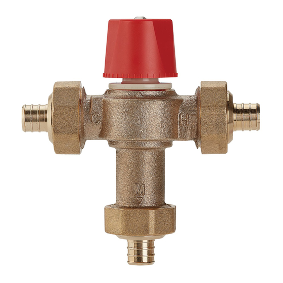
Series LF1170 and LFL1170
Hot Water Temperature Control Valves
Size:
⁄
",
⁄
", 1"
1
3
2
4
WARNING
!
Read this Manual BEFORE using this equipment.
Failure to read and follow all safety and use information
can result in death, serious personal injury, property
damage, or damage to the equipment.
Keep this Manual for future reference.
WARNING
!
FAILURE TO COMPLY WITH PROPER INSTALLATION AND
MAINTENANCE INSTRUCTIONS COULD CONTRIBUTE TO THE VALVE
FAILURE.
This Hot Water Master Tempering Valves cannot be used for temper-
ing water temperature at fixtures. Severe bodily injury (i.e., scalding
or chilling) and/or death may result depending upon system water
pressure changes and/or supply water temperature changes. ASSE
standard 1016, 1069 or 1070 listed devices should be used at fix-
tures to prevent possible injury.
These Hot Water Tempering Valves are designed to be installed at or near
the boiler or water heater. They are not designed to compensate for sys-
tem pressure fluctuations and should not be used where ASSE standard
1016, 1069 or 1070 devices are required. These valves should never be
used to provide "anti-scald" or "anti-chill" service.
The components of the system must be of materials with a construction
capable of withstanding the high limit output temperatures of the water
heating source.
WARNING
!
Need for Periodic Inspection and Yearly Maintenance:
Periodic inspection and yearly maintenance by a licensed
contractor is required. Corrosive water conditions, tempera-
tures over 200°F, unauthorized adjustments or repair could
render the valve ineffective for service intended. Regular
checking and cleaning of the valve's internal components and
check stops helps assure maximum life and proper product
function. Frequency of cleaning and inspection depends upon
local water conditions.
WARNING
!
You are required to consult the local building and plumbing
codes prior to installation. If the information in this manual
is not consistent with local building or plumbing codes,
the local codes should be followed. Inquire with governing
authorities for additional local requirements.
LF1170-UT-M2
Installation
WARNING
!
Valve should be installed and adjusted by a licensed contractor
in accordance with local codes and ordinances. Further, this
valve should be installed in a location where it is accessible for
cleaning, service or adjustment.
1. Close both the hot and cold water shutoff valves upstream
nearest to the intended installation.
2. Bleed the remaining water from the system.
3. Connect the water supply to valve as shown in Figure 1 or 2,
depending on the application. Supply piping must be flushed
clean before making connections to the valve.
NOTICE
To prolong the life of the Model LF1170-M2 or LFL1170-M2
valve, it is recommended that it be trapped as shown (Figure1):
i.e. the hot water inlet to the LF1170-M2 valve should be 8" –
12" (200 – 305mm) below the hot water supply feed.
4. Valve can be installed in any position. Note: the inlet hot sup-
ply is to be connected to the "H" side of the valve, the cold
supply side to the "C" side and the mixed water outlet to the
"M" side.
5. Make sure union nuts are placed over tailpieces prior to
soldering or threading to pipe.
6. For valves with Quick-Connect tailpieces refer to "Quick-
Connect Installation" instructions below.
NOTICE
To prevent damage to valve from excessive heat during
soldering, remove unions and gaskets from valve body prior to
soldering.
WARNING
!
Use caution when soldering. Protect yourself and others. FUMES
AND GASES can be hazardous to your health. HEAT RAYS (INFRARED
RADIATION) from flame or hot metal can injure eyes.
7. After soldering, flush piping and install valve using filter wash-
er on hot and cold water inlet and fiber washer on the mixed
water outlet.
8. Start-up: Open cold water supply, then hot water supply.
Inspect for leaks.
9. Adjust temperature to desired setting (see Temperature
Adjustment Section).
IS-1170-M2_L1170-M2
LF1170-QC-M2
Advertisement
Table of Contents

Related Manuals for Watts LF1170 Series


Summary of Contents for Watts LF1170 Series
- Page 1 http://waterheatertimer.org/How-to-save-hot-water-using-mixing-valve.html IS-1170-M2_L1170-M2 Instructions Series LF1170 and LFL1170 Hot Water Temperature Control Valves Size: ⁄ ", ⁄ ", 1" WARNING Read this Manual BEFORE using this equipment. Failure to read and follow all safety and use information can result in death, serious personal injury, property damage, or damage to the equipment.
- Page 2 To prolong the life of the valve, it is recommended the valve be trapped as shown † Devices tested to ASSE 1016, ASSE 1070 or ASSE 1069 such as Watts LFUSG, LFL111 or LFMMV should be used at fixture to prevent possible injury.
- Page 3 Period Inspection/Maintenance Pressure — Temperature This valve requires periodic inspection and verification of the out- Minimum Supply Pressure (Static): 30psi (207 kPa) let temperature by a licensed contractor. Corrosive water condi- Inlet Temperatures: hot inlet, 120°F – 200°F (49°C – 93°C), tions, hot inlet water temperature over 200°F (93°C), unauthor- cold inlet, 40°F –...
- Page 4 For more information: www.watts.com/prop65 Limited Warranty: Watts Regulator Co. (the “Company”) warrants each product to be free from defects in material and workmanship under normal usage for a period of one year from the date of original shipment. In the event of such defects within the warranty period, the Company will, at its option, replace or recondition the product without charge.
Need help?
Do you have a question about the LF1170 Series and is the answer not in the manual?
Questions and answers