Table of Contents
Advertisement
Quick Links
Advertisement
Table of Contents

Related Manuals for HACH LANGE BUHLER 3010


Summary of Contents for HACH LANGE BUHLER 3010
- Page 1 DOC013.52.90205 BÜHLER 3010, 3900, 4010–4410 Short Manual 1/2017, Edition 3...
-
Page 3: Table Of Contents
Table of contents Section 1 Specifications ........................5 1.1 Dimensions ............................6 Section 2 General information....................... 9 2.1 Safety information..........................9 2.1.1 Hazard information in this manual ..................... 9 2.1.2 Warning labels ........................... 9 2.2 General information .......................... 10 2.2.1 Areas of application ......................... 10 2.2.2 Functional description ...................... - Page 4 Section 4 Operation ..........................35 4.1 Control unit operation ........................35 4.1.1 Password..........................35 4.1.2 Programming..........................35 4.1.2.1 Keyboard layout/function ....................35 4.2 Normal operation..........................37 4.2.1 Replace the sample bottles (3010, 3900, 4010, 4110, 4211)...........38 4.2.2 Sampling (4411 with 12 or 24 bottles)..................40 4.2.3 Sampling (4411 with 2 or 4 bottles)..................44 Section 5 Maintenance and cleaning....................49 5.1 Maintenance tasks ..........................49 5.2 Cleaning ............................49...
-
Page 5: Section 1 Specifications
Section 1 Specifications Specifications are subject to change without notice. Electrics Power supply 230 V/50 Hz.,16 A fuse Power consumption approx. 350 VA Environment Medium temperature 0 to +40 °C [32 to 104 °F] Ambient temperature –20 to +40 °C [–4 to 104 °F] Delivery height <... -
Page 6: Dimensions
Specifications 1.1 Dimensions pqrs wxyz mm [in.] mm [in.] mm [in.] mm [in.] BÜHLER 3010 760 [30] 1100 [43.3] 1640 [64.6] 725 [28.5] BÜHLER 4010 605 [23.8] 1325 [52.2] 1895 [74.6] 645 [25.4] BÜHLER 4110 605 [23.8] 1475 [58.1] 2030 [79.9] 645 [25.4] BÜHLER 4210 (23 bottles) - Page 7 Specifications mm [in.] mm [in.] mm [in.] mm [in.] BÜHLER 3900 625 [24.6] 1125 [44.3] 1695 [66.7] 648 [25.5] Figure 2 Dimensions 3900...
- Page 8 Specifications...
-
Page 9: Section 2 General Information
Section 2 General information 2.1 Safety information Please read this entire manual before the equipment is unpacked, set up or operated. Pay attention to all danger and caution statements. Personal injury or damage to the equipment could occur if they are not observed. To ensure that the protection provided by this equipment is not impaired, do not use or install this equipment in any manner other than that specified in this manual. -
Page 10: General Information
General information When this symbol appears on the product, it identifies the location of a fuse or a current limiter. Electrical equipment marked with this symbol may not be disposed of in European domestic or public disposal systems after 12 August 2005. In conformity with European local and national regulations (EU Directive 2002/96/EC), European electrical equipment users must now return old or end-of life equipment to the manufacturer for disposal at no charge to the user. - Page 11 General information Figure 4 Scope of delivery (3900–4410)
- Page 12 General information...
-
Page 13: Section 3 Installation
Section 3 Installation DANGER Only qualified experts should conduct the tasks described in this section. DANGER Select an appropriate installation location for the instrument. Plan out the mechanical mount·before positioning poles or drilling holes. Make sure the mount has a sufficient bearing capacity. The dowels must be selected and authorized according to the condition of the wall. -
Page 14: Mechanical Installation
Installation 3.1 Mechanical installation DANGER Select an appropriate installation location for the instrument. Plan out the mechanical mount·before positioning poles or drilling holes. Make sure the mount has a sufficient bearing capacity. The dowels must be selected and authorized according to the condition of the wall. The manufacturer shall accept no liability if the instrument is installed incorrectly. -
Page 15: Select Installation Location
Installation 3.1.2 Select installation location ≥ 50 mm ≥ [2 in] ≥ 500 mm ≥ 500 mm ≥ [20 in] ≥ [20 in] pqrs wxyz 2500 mm [100 in] mm [in.] mm [in.] mm [in.] mm [in.] BÜHLER 3010 760 [30] 1100 [43.3] 1640 [64.6] 725 [28.5]... -
Page 16: Unpacking
Installation mm [in.] mm [in.] ≥ Ø12 × 60 mm BÜHLER 3010 730 [28.7] 384 [15.1] BÜHLER 3900 660 [26] 383 [15.1] BÜHLER 4010 660 [26] 383 [15.1] BÜHLER 4110 660 [26] 383 [15.1] BÜHLER 4210 660 [26] 383 [15.1] BÜHLER 4410 770 [30.3] 500 [19.7]... -
Page 17: Set Up
Installation Figure 9 Move the equipment from the transport pallet (3900–4410) 3.1.4 Set up BÜHLER 3010 Figure 10 Set up the equipment (3010) - Page 18 Installation BÜHLER 3900 BÜHLER 4010 BÜHLER 4210 BÜHLER 4410 BÜHLER 4110 Figure 11 Set up the equipment (3900, 4010-4410) ³ 17 mm > 80 Nm ³ Ø12 × 60 mm Figure 12 Align and secure the equipment...
-
Page 19: Electrical Connections
Installation 3.2 Electrical connections DANGER Only qualified experts should conduct the tasks described in this section. DANGER Do not connect the electrical supply to the mains if the equipment has not been wired and fused correctly. Sufficiently protect the electrical power supply against short circuits. For the external power supply, always connect a residual-current circuit breaker·(trip current max.: 30 mA) between the mains and the system. -
Page 20: Electrical Installation
Installation 3.2.1 Electrical installation 3.2.1.1 Prepare the electrical installation (3010) Figure 13 Loosen the screws and remove the cover (3010) Figure 14 Feed cable through (3010) -
Page 21: Prepare The Electrical Installation (3900-4410)
Installation 3.2.1.2 Prepare the electrical installation (3900–4410) Figure 15 Loosen the lid screws and open the lid (3900–4410) Figure 16 Lift up the cover (3900–4410) -
Page 22: Wiring Diagram (3010)
Installation 3.2.1.3 Wiring diagram (3010) 2 3 4 5 6 111214 Figure 17 Wiring diagram (3010) 3.2.1.4 Wiring diagram (3900–4410) DC 12 V Out: AC 250 V / 2 × 8 A Kontaktbelegung: Relais Pin assignment: relay Figure 18 Wiring diagram (3900–4410) -
Page 23: Complete The Electrical Installation (3010)
Installation 3.2.1.5 Complete the electrical installation (3010) Figure 19 Attach cover 3.2.1.6 Complete the electrical installation (3900–4410) Figure 20 Shut the cover If suction tube is not connected immediately, close the housing lid as described in Figure 24, page 25 Figure 25, page... -
Page 24: Commission The Equipment
Installation 3.3 Commission the equipment Figure 21 Key storage location (for key option) 3.3.1 Tube connection Figure 22 Feed the suction tube though housing opening... - Page 25 Installation Figure 23 Screw in the union nut Figure 24 Close the lid...
- Page 26 Installation Figure 25 Screw down the lid tightly Position the tubes in accordance with the following installation diagram. –20–+40 °C [–4–+104 °F] £ 30.000 mm £ [100 ft] 0–+40 °C [+32–+104 °F] > 50 µs Figure 26 Installation diagram...
-
Page 27: Set The Individual Sample Volumes
Installation 3.3.2 Set the individual sample volumes 3.3.2.1 Plastic dosing vessel Figure 27 Release the plastic dosing vessel Figure 28 Remove the plastic dosing vessel... - Page 28 Installation V-Probe [mL] = 150 mL Figure 29 Cut the dosing tube to set the sample volume Figure 30 Reinstall the plastic dosing vessel...
-
Page 29: Glass Dosing Vessel
Installation 3.3.2.2 Glass dosing vessel 100 mL = 100 mL Figure 31 Adjust the dosing pipe to set the sample volume 3.3.2.3 Dosing vessel for flow-proportional sampling 100 mL = 100 mL Figure 32 Calibrate the flow-proportional dosing vessel via the service menu... -
Page 30: Bypass Dosing Vessel
Installation DP = 0 [hPa, bar] Figure 33 The flow-proportional dosing vessel may only be used, if there is NO counter pressure 3.3.2.4 Bypass dosing vessel Notüberlauf Emergency overflow 4–20 L/Min. + mL – mL DP = 0 [hPa, bar] Figure 34 Set the sample volume of the bypass dosing vessel... -
Page 31: Flush Water Connection And Drain (4210/4410)
Installation 3.3.2.5 Flush water connection and drain (4210/4410) Schlauchtülle: ¾” Hose nozzle: ¾" Hose: Ø (internal) 25 mm Schlauch Ø (innen) 25 mm Figure 35 Flush water connection and drain (4210) Hose nozzle: ¾" Schlauchtülle ¾” Schlauch ID 25 mm Hose: Ø... -
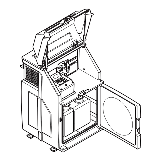
Page 32: Preparing The Sample Containers (3010, 3900, 4010, 4110, 4210)
Installation 3.3.3 Preparing the sample containers (3010, 3900, 4010, 4110, 4210) Figure 37 Place the empty bottles in the housing Figure 38 Close the door 3.3.4 Connect the equipment to the mains Make sure that: • The equipment has been fully prepared for commissioning •... - Page 33 Installation Figure 39 Rating label [10 ft] [10 ft] Figure 40 Possible connection configurations...
- Page 34 Installation...
-
Page 35: Section 4 Operation
Section 4 Operation 4.1 Control unit operation All the equipment functions are software-controlled. 4.1.1 Password Password to program sampler and to change settings is: 6299 4.1.2 Programming The menu structure resembles the directory structure of a computer hard drive and is divided into main menus and sub menus. - Page 36 Operation Table 1 Key functions (Continued) Select from within a menu Arrow keys Confirm the selection Enter key (automatically marked with a Enter/change values Arrow keys Confirm the entered values Enter key Return to the next superordinate menu level Back key Numeric Enter values...
-
Page 37: Normal Operation
Operation Figure 42 Start the program Depending on the program range, • an activity is started or • the next menu item is automatically selected. Note: The general rule: If you press Back, – the activity is cancelled or – the navigation takes one step back in the menu. 4.2 Normal operation The described normal operation applies to several models (e.g.) 3010, 3900, 4010, 4011, 4110, 4210, 4411). -
Page 38: Replace The Sample Bottles (3010, 3900, 4010, 4110, 4211)
Operation 4.2.1 Replace the sample bottles (3010, 3900, 4010, 4110, 4211) Figure 43 Open the door Figure 44 Remove the full bottles... - Page 39 Operation Figure 45 Replace with empty bottles Figure 46 Close the door...
-
Page 40: Sampling (4411 With 12 Or 24 Bottles)
Operation 4.2.2 Sampling (4411 with 12 or 24 bottles) Figure 47 Press PAUSE to suspend the current program (4411 with 12 or 24 bottles) Figure 48 Select to remove the sample (4411 with 12 or 24 bottles) - Page 41 Operation Figure 49 Select bottle number (4411 with 12 or 24 bottles) Figure 50 Swivel out the sample faucet (4411 with 12 or 24 bottles)
- Page 42 Operation Figure 51 Press the lever to open the sample faucet (4411 with 12 or 24 bottles) Figure 52 Swivel the lever back to close the sample faucet (4411 with 12 or 24 bottles)
- Page 43 Operation Figure 53 Swivel in the sample faucet (4411 with 12 or 24 bottles) Figure 54 Select to continue the program (4411 with 12 or 24 bottles)
-
Page 44: Sampling (4411 With 2 Or 4 Bottles)
Operation 4.2.3 Sampling (4411 with 2 or 4 bottles) Figure 55 Select pause (4411 with 2 or 4 bottles) Figure 56 Release the bottle holder (4411 with 2 or 4 bottles) - Page 45 Operation Figure 57 Pull out the bottle holder and take sample (4411 with 2 or 4 bottles) Figure 58 Select to remove sample (4411 with 2 or 4 bottles)
- Page 46 Operation Figure 59 Select the bottle number (4411 with 2 or 4 bottles) Figure 60 Push the bottle holder back in and secure (4411 with 2 or 4 bottles)
- Page 47 Operation Figure 61 Select to continue program (4411 with 2 or 4 bottles)
- Page 48 Operation...
-
Page 49: Section 5 Maintenance And Cleaning
Section 5 Maintenance and cleaning DANGER Only qualified experts should conduct the tasks described in this section. WARNING Please observe the following points for the use of chemicals and/or waste water: Wear protective clothing: – Laboratory coat – Protective eyewear –... - Page 50 Maintenance and cleaning Figure 62 NEVER rotate the distribution unit manually Figure 63 Clean the distribution unit...
-
Page 51: Clean The Dosing Vessel
Maintenance and cleaning 5.2.2 Clean the dosing vessel Figure 64 Release the dosing vessel Figure 65 Remove the dosing vessel... - Page 52 Maintenance and cleaning Figure 66 Clean the dosing vessel Figure 67 Insert the dosing vessel...
-
Page 53: Troubleshooting
Maintenance and cleaning 5.3 Troubleshooting If the equipment does not function as required, check the fuse and replace if necessary. 5.3.1 Open the housing to change the fuse (3010) Figure 68 Open the lid and detach the cover (3010) Figure 69 Remove the safety cover (3010) -
Page 54: Open The Housing To Change The Fuse (3900-4410)
Maintenance and cleaning 5.3.2 Open the housing to change the fuse (3900–4410) Open the housing lid as described in Figure 15, page 21 Figure 16, page 5.3.3 Change the fuse 5 × 20 mm 8 A (träge) (inactive) Figure 70 Fuse support If the error is not rectified, please contact the customer service of the manufacturer (refer Contact information, page 61). -
Page 55: Reassemble The Housing (3010)
Maintenance and cleaning 5.3.4 Reassemble the housing (3010) Figure 71 Install the safety cover (3010) Figure 72 Close the housing (3010) -
Page 56: Reassemble The Housing (3900-4410)
Maintenance and cleaning 5.3.5 Reassemble the housing (3900–4410) Close the housing lid as described in Figure 20, page Figure 24, page 25 Figure 25, page 5.4 Instrument decommissioning and storage 1. Remove all liquids and, if necessary, solid matter from the infeed and outfeed lines and sample containers and clean as required. -
Page 57: Section 6 Spare Parts And Accessories
Section 6 Spare parts and accessories 6.1 Spare parts Description Cat. no. Short Manual (xx = language number) Doc013.xx.90205 Full User Manual (xx = language number) Doc023.xx.90144 BM80070 BM69452 BM80044 350 mL Kunststoff - Dosiereinheit Plastic dosing vessel BM900715 BM69301 12 ×... - Page 58 Spare parts and accessories BM900053 BM69401 BM69402 BM30004 350 mL Glass dosing vessel (350 ml) Glas - Dosiereinheit (350 mL) BM900674 BM69301 12 × 2 BM69302 4 × 1,5 Figure 74 Glass dosing vessel (350 ml)
- Page 59 Spare parts and accessories BM900053 BM69401 BM69402 BM30005 500 mL Glas - Dosiereinheit (500 mL) Glass dosing vessel (500 ml) BM900243 BM69301 12 × 2 BM69302 4 × 1,5 Figure 75 Glass dosing vessel (500 ml)
- Page 60 Spare parts and accessories BM69402 BM30027 250 mL Bypass dosing vessel (glass) Bypass - Dosiereinheit (Glas) BM900239 BM69301 12 × 2 BM69317 20 × 2 Figure 76 Glass dosing vessel (flow)
-
Page 61: Section 7 Warranty And Liability
Section 7 Warranty and liability The manufacturer warrants that the product supplied is free of material and manufacturing defects and undertakes the obligation to repair or replace any defective parts at zero cost. The warranty period for instruments is 24 months. If a service contract is taken out within 6 months of purchase, the warranty period is extended to 60 months. - Page 62 Warranty and liability...
- Page 63 Fax (970) 669-2932 Fax +49 (0) 2 11 52 88-210 Tel. +41 22 594 6400 orders@hach.com info-de@hach.com Fax +41 22 594 6499 www.hach.com www.de.hach.com © Hach Company/Hach Lange GmbH, 2010–2011, 2017. All rights reserved. Printed in Germany 1/2017, Edition 3...
Need help?
Do you have a question about the BUHLER 3010 and is the answer not in the manual?
Questions and answers