Advertisement
Quick Links
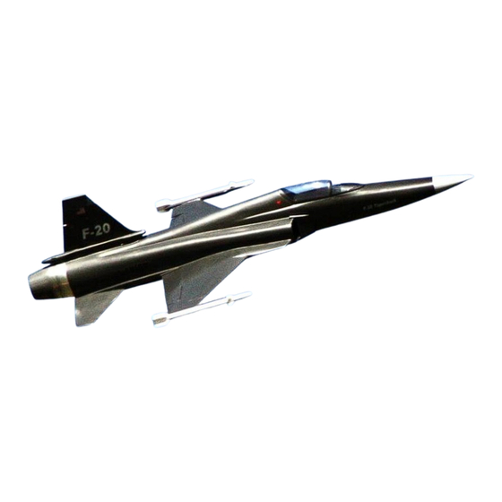
High End Technology 90mm F-20
Assembly Manual
Specifications:
- Length: 57" 1430MM
- Wingspan: 29.5" 750MM
-Weight: 3lbs 6oz
- Full Intake/Exhaust ducting with NO cheater holes
- EDF - HET-9305 FAN
- Motor - HET-700-68-1400
- ESC HET-100HV
- Lipo 10S 5000mah, 35C
- 8 servos 2 Elevator, 2 Ailerons, 2 Flaps, 1 Rudder, 1 Steering
High
E nd
T echnology
R C
A sia
P acific
L td.
Room
2 202
C heung
T at
C entre
18
C heung
L ee
S treet
C haiwan
Hong
K ong
Phone:
8 52
2 187
2 622
www.HighEndRC.com
1
www.EJF.com
Advertisement

Related Manuals for High-End Technology F-20

Summary of Contents for High-End Technology F-20
- Page 1 High End Technology 90mm F-20 Assembly Manual Specifications: - Length: 57" 1430MM - Wingspan: 29.5" 750MM -Weight: 3lbs 6oz - Full Intake/Exhaust ducting with NO cheater holes - EDF - HET-9305 FAN - Motor - HET-700-68-1400 - ESC HET-100HV - Lipo 10S 5000mah, 35C - 8 servos 2 Elevator, 2 Ailerons, 2 Flaps, 1 Rudder, 1 Steering High ...
- Page 2 Table of Contents Introduction Pg 3 Out of the Box Pg.4 Wing Assembly Pg.5-7 Vertical Stabilizer and Rudder Assembly Pg.8-9 Elevator Assembly Pg.8- 10 Retract Mount Assembly Pg.11-14 Fan Mount Assembly Pg.14-15 Fan Unit and Thrust Tube Installation Pg.15-17 Final Equipment Placement Pg.13 Center of Gravity and Initial settings Pg.17-18...
-
Page 3: Additional Items Required
Introduction Although the F-20 goes together very easily, there is still some construction involved, this is NOT a plane for beginners, and you should have some experience with putting together ARFs. Please look carefully at the pictures and explanations carefully before performing any work. There are many ways to build a plane, eg servo mounting methods, it is up to the builder to fully test their airplane and flight controls before flight. - Page 4 OUT OF THE BOX PICTURE ON LEFT: Top side of the plane place together for pictures. 1X fuselage, 2X Wings, 1X vertical stab and rudder, 2X elevators, 2X Missile Rails, Ailerons, flaps and missiles not shown in the pictures PICTURE ON RIGHT: Bottom of the airplane, Landing gear and servo locations already built into the plane. PICTURE ON LEFT: Few formers needed to build, top and center are battery tray, the rest are Fan Mounting formers.
-
Page 5: Wing Construction
My Fuselage did not have a slot for the Aileron servo wire to go through, I used the wing to measure out where the servo would exit and cut a slot. NOTE: When I received the F-20, the wings had already been glued to the fuselage, I will use some pictures from the HET F-16 as reference. - Page 6 WINGS CONTINUED PICTURE ON LEFT: Check the Aileron and Rudder hinge slots to make sure the hinges fit properly. If needed, use and exacto knife open up further just make sure to get them in the middle of the leading edge of the Aileron or Flap. PICTURE ON RIGHT: I am checking the Hinge Slot or hole in the HET F-16 Aileron.
- Page 7 WINGS CONTINUED PICTURE ON LEFT: With the servo in place I make balsa mounts for the cover. PICTURE ON RIGHT: Aileron is done. PICTURE ON LEFT: Made a mount for the Flap servo to have it removable. PICTURE ON RIGHT: Glue in the Mount and Servo to the wing. NOTE the routing of the Aileron and Flap servo wiring is not in the fuselage.
- Page 8 VERTICAL FIN / RUDDER PICTURE ON LEFT: Use your servo to measure and cu the access for the servo, there are many ways to mount a servo. PICTURE ON RIGHT: If you want to be able to service/access your servo, install it from inside the fuselage, you can always remove and make changes.
- Page 9 PICTURE ON LEFT: Servo Control Horn Cut out on the Vertical stab PICTURE ON RIGHT: Sand the fuselage and the inside of the Vertical Fin, the example above is the F-16 shown for illustration. Test fit everything and then satisfied, Glue the vertical fin the body. PICTURE ON LEFT: Connect your servo to the Rudder now that your vertical fin is glued to the body.
- Page 10 ELEVATORS PICTURE ON LEFT: The elevator already comes built and ready to be mounted to the fuselage. The control Horn is glued and then uses two screws for additional support, the two screws for the control horn can bind with the fuselage. Sand the elevator rod lightly making sure you do NOT bend the rod.
- Page 11 ELEVATORS CONTINUED PICTURE ON LEFT: The body has an access door where you could use to mount the servo, but there is enough room to insert the servo through the Fan access door or the back of the jet. PICTURE ON RIGHT: If you want to make the servo access door small, you can use the Aileron servo cover to mark the size on the bottom of the fuselage.
- Page 12 RETRACTS PICTURE ON LEFT: Mark and tape the location of the NOSE gear door opening. There is a panel line on the front and back where the door should be cut. PICTURE ON RIGHT: The nose gear opening is about 1.75 inch wide (44.45mm), and .75 inch (19.05mm) from the panel line in the fuselage.
- Page 13 RETRACTS CONTINUED PICTURE ON LEFT: Connect the Air-Lines to the retracts, leave enough room on each so that you can pull them ou through the fan access opening, make sure both Air lines are the same length. PICTURE ON LEFT: Each tire comes with three plastic washers; You will need to add them to the axle to prevent the wheel from touching the strut.
-
Page 14: Fan Mounting
RETRACTS CONTINUED PICTURE ABOVE: Connect your retracts as shown, I used two different color air-lines for illustration. The Red line above goes to the retracts, the wing. FAN MOUNTING PICTURE ON LEFT: This are the formers included with the prototype plane. Fan mounting former, there are four rails and two formers, the four rails are doubled up/glued together to make two rails and then glue them to the two formers, you can use CA or 5 minute Epoxy. - Page 15 FAN MOUNTING CONTINUED PICTURE ON LEFT: Sand the inside of the fuselage where the Fan mount will need to be glued to the fuselage, then clean all dust to have it ready for the glue. PICTURE ON RIGHT: Test fit the fan mount to the fuselage and make sure it does not touch any part of the intake, you can at this time also check the fan you are going to use.
- Page 16 FAN MOUNTING CONTINUED PICTURE ON LEFT: Assemble the Fan and motor of your choice, This is the HET 9305 Fan and the HET 700-68-1400 motor. PICTURE ON LEFT: Fan and motor assembled and ready to install. This the perfect time to install the connectors for your Speed Controller (ESC).
- Page 17 Rudder: 1 Inch or as much as you can get Flaps: 1 Inch OPTIONAL (WARNING: The F-20 will climb when the flaps are lowered) CG 9.00" 228.6MM Measured from the intake back into the wing. PICTURE ON LEFT: Aileron LOW Rate travel measured half way out on Aileron.
- Page 18 W A R N I N G! Although the F-20 is a stable airplane, it is not a trainer or first EDF airplane. This airplane is capable of very high speeds and therefore can cause serious personal injury and property damage. We strongly urge you to seek the help of an AMA approved instructor if this is your first aircraft of this type.
Need help?
Do you have a question about the F-20 and is the answer not in the manual?
Questions and answers