Table of Contents
Advertisement
Quick Links
Specifications are subject to change without notice for further improvement.
MC-UG323-00
MC-UG327-00
Product Color: Dynamic Blue (MC-UG323-00)
Deep Burgandy (MC-UG327-00)
Destination:
North America
© 2012 PANASONIC APPLICANCES COMPANY
OF AMERICA. All rights reserved. Unauthorized
copying and distribution is a violation of law.
Order Number MAC1206005CE
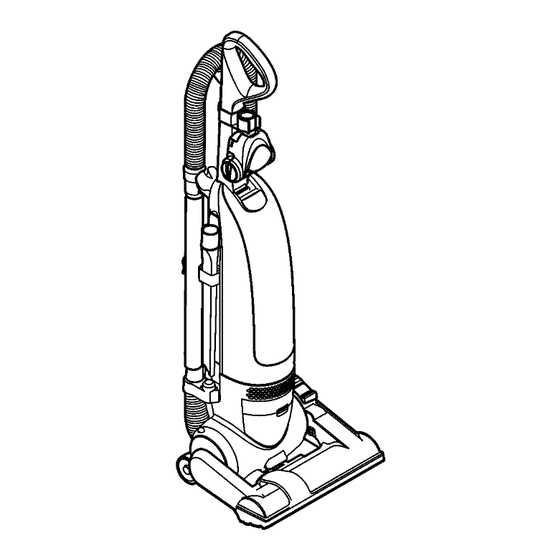
Vacuum Cleaner
Advertisement
Table of Contents

Summary of Contents for Panasonic MC-UG323-00
- Page 1 Order Number MAC1206005CE Vacuum Cleaner MC-UG323-00 MC-UG327-00 Product Color: Dynamic Blue (MC-UG323-00) Deep Burgandy (MC-UG327-00) Destination: North America Specifications are subject to change without notice for further improvement. © 2012 PANASONIC APPLICANCES COMPANY OF AMERICA. All rights reserved. Unauthorized copying and distribution is a violation of law.
-
Page 2: Table Of Contents
2.5. Packing Materials 1.1. Wiring Diagram (MC-UG323-00) 3 SERVICE PROCEDURES 1.2. Wiring Diagram (MC-UG327-00) 3.1. Upper Body 1.3. Wire Management Drawing (MC-UG323-00) 3.2. Lower Plate 1.4. Wire Management Drawing (MC-UG37-00) 3.3. Agitator 2 EXPLODED VIEW AND PARTS LIST 3.4. Motor 2.1. -
Page 3: Wiring Schematics
MC-UG323-00 / MC-UG327-00 / 1 WIRING SCHEMATICS 1.1. Wiring Diagram (MC-UG323-00) 1.2. Wiring Diagram (MC-UG327-00) -
Page 4: Wire Management Drawing (Mc-Ug323-00)
MC-UG323-00 / MC-UG327-00 / 1.3. Wire Management Drawing (MC-UG323-00) NOTE: For general servicing, it is necessary to eliminate pinching of any wire during reassembly. After servicing any electrical component or electrical enclosure, the unit should be reassembled and checked for dielectric breakdown or current leakage. -
Page 5: Wire Management Drawing (Mc-Ug37-00)
MC-UG323-00 / MC-UG327-00 / 1.4. Wire Management Drawing (MC-UG37-00) NOTE: For general servicing, it is necessary to eliminate pinching of any wire during reassembly. After servicing any electrical component or electrical enclosure, the unit should be reassembled and checked for dielectric breakdown or current leakage. -
Page 6: Exploded View And Parts List
MC-UG323-00 / MC-UG327-00 / 2 EXPLODED VIEW AND PARTS LIST 2.1. Upper Body 2.1.1. Exploded View 2.1.2. Parts List Ref. No. Part No. Part Name & Description Quantity Remarks AC40KDTGZV07 DUST COMPARTMENT MC-UG323-00 AC40KDVKZV07 DUST COMPARTMENT MC-UG327-00 AC01BDTGZV07 HANDLE AC21KDTGZV07... -
Page 7: Lower Body
MC-UG323-00 / MC-UG327-00 / 2.2. Lower Body 2.2.1. Exploded View... - Page 8 MC-UG323-00 / MC-UG327-00 / 2.2.2. Parts List Ref. No. Part No. Part Name & Description Quantity Remarks AC40KDSBZV07 DUST COMPARTMENT MC-UG323-00 AC40KDRZZV07 DUST COMPARTMENT MC-UG327-00 AXTN4+16BFY SCREWS (10 PER BAG) MC-UG323-00: Qty. 7 AC43NDRZZ000 BRAKE LEVER MC-UG327-00 AC47NATCZ00 SPRING MC-UG327-00: Qty. 2...
-
Page 9: Nozzle Housing
MC-UG323-00 / MC-UG327-00 / 2.3. Nozzle Housing 2.3.1. Exploded View 2.3.2. Parts List Ref. No. Part No. Part Name & Description Quantity Remarks AC01ADTGZCUT BODY NOZZLE HOUSING (DECO) MC-UG323-00 AC01ADVKZRU3 BODY NOZZLE HOUSING (DECO) MC-UG327-00 AC10ADRZZV07 FURNITURE GUARD AC58ACRYZ000 SPRING (NOZZLE) -
Page 10: Handle Assembly
MC-UG323-00 / MC-UG327-00 / 2.4. Handle Assembly 2.4.1. Exploded View 2.4.2. Parts List Ref. No. Part No. Part Name & Description Quantity Remarks AC95BDSAZC0T HANDLE UNIT MC-UG323-00 AC95BDRZZR03 HANDLE UNIT MC-UG327-00 AC64BDSAZV07 HANDLE MC-UG323-00 AC64BDRZZV07 HANDLE MC-UG327-00 AC50BDRZZC0T HANDLE GRIP... -
Page 11: Packing Materials
Part Name & Description Quantity Remarks AC61ZDTGZU00 Carton Box MC-UG323-00 AC61ZDVKZU00 Carton Box MC-UG327-00 AC01ZDTGZ000 Operating Instructions MC-UG323-00 AC01ZDVKZ000 Operating Instructions MC-UG327-00 AC94ZDTGZ000 Packing Assembly MC-UG323-00, includes items 1, 2, and A-H AC94ZDVKZ000 Packing Assembly MC-UG327-00, includes items 1, 2, and A-G... -
Page 12: Service Procedures
MC-UG323-00 / MC-UG327-00 / 3 SERVICE PROCEDURES 3.1. Upper Body 3.1.1. Removal 1. Remove one (1) screw from back of vacuum cleaner. 2. Remove dust cover. 6. Remove fastener guide. 3. Remove dust bag. 4. Remove two (2) screws. 5. Separate upper body and lower body. -
Page 13: Lower Plate
MC-UG323-00 / MC-UG327-00 / 3.1.2. Installation 1. Reinstall fastener guide into upper body and reinstall two (2) screws. 4. Reinstall dust bag and dust cover. 3.2. Lower Plate 3.2.1. Removal 1. Turn off and unplug vacuum cleaner. 2. Lay vacuum cleaner with bottom facing upwards and nozzle flat 3. -
Page 14: Agitator
MC-UG323-00 / MC-UG327-00 / 3.3. Agitator 3.3.1. Removal 1. Remove lower plate (See Lower Plate - Removal). 2. Lay vacuum cleaner with bottom facing upwards and nozzle flat 3. Remove agitator carefully lifting out. 3.2.2. Installation 1. Place the vacuum cleaner in the upright position standing on the handle. -
Page 15: Motor
MC-UG323-00 / MC-UG327-00 / any electrical component or electrical enclosure, the unit should be reassembled and checked for dielectric breakdown or current leakage. 3.4. Motor 3.4.1. Removal 1. Remove upper body (See Upper Body - Removal). 2. Remove nozzle hose from body by (1) pressing in locking tab and (2) sliding up and out of retaining slot. - Page 16 MC-UG323-00 / MC-UG327-00 / 15. Discard motor if defective. 3.4.2. Installation 1. Reconnect motor lead wires (refer to wiring diagram if necessary). 2. Reinstall motor support rubbers, motor flange (MC-UG327 only) and noise suppressor. 3. Reinstall motor assembly into vacuum cleaner with thermal protector facing down.
-
Page 17: Cord Reel (Mc-Ug327-00)
MC-UG323-00 / MC-UG327-00 / 3.5. Cord Reel (MC-UG327-00) 3.6. Power Cord (MC-UG323-00) 3.5.1. Removal 3.6.1. Removal 1. Remove motor cover (See Motor - Removal). 1. Remove motor cover (See Cord Reel - Removal). 2. Cut black and white cord reel lead wires close to cord reel. -
Page 18: On/Off Switch
MC-UG323-00 / MC-UG327-00 / 3.7. On/Off Switch 3.7.1. Removal 1. Remove lower plate (See Lower Plate - Removal). 2. Remove agitator and belt (See Agitator - Removal). 3. Remove motor cover (See Motor - Removal). 4. Remove nozzle (See Motor - Removal).


Need help?
Do you have a question about the MC-UG323-00 and is the answer not in the manual?
Questions and answers