
Related Manuals for Telebyte 458-3SLB

Summary of Contents for Telebyte 458-3SLB
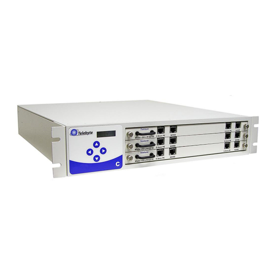
- Page 1 “Results You Can Count On” Model 458-3SLB (3-Slot Chassis) Rev D Date of Publication: 02/25/2019 Line modules not included.
- Page 2 This compact unit is extremely easy to use and a perfect fit when only one, two or three line modules are required. The Model 458-3SLB is ideally suited for testing DSL modems and other bandwidth-compliant telecom devices in a high- volume production line environment.
- Page 3 TELEBYTE, INC. warrants its broadband simulation equipment to be free from defects in material and workmanship, under normal and proper use and in its unmodified condition, for 12-months, starting on the date it is delivered for use. TELEBYTE’S sole obligation under this warranty shall be to furnish parts and labor for the repair or replacement of products found by TELEBYTE to be defective in material or workmanship during the warranty period.
- Page 4 Equipment Safety Do not remove or insert Line Modules with the 458-3SLB Power in the ON state. Set the Power Entry switch at the rear of the system to the OFF state prior to Module removal and set it to the...
-
Page 5: Table Of Contents
Table of Contents 1.0 Introduction ............................1 Chassis/Control Module ........................1 Line Module Series ......................... 2 2.0 Specifications........................... 3 3.0 RS-232/Ethernet Controls ....................... 4 RS-232 Connections ........................4 RS-232/Ethernet Connections ......................5 User Command Interface ........................ 5 RS-232 Mode Command List ......................5 4.0 IEEE Controls .......................... -
Page 6: Introduction
1.0 Introduction The Model 458-3SLB (3-Slot Chassis) is a compact, versatile unit that accepts 1, 2 or 3 line modules and controls from 1 - 24 channels. It is ideal for testing DSL modems and other bandwidth-compliant telecom devices in a high-volume production environment. While it can be used as a stand-alone unit, the built-in Control Module interfaces with a PC via RS-232, IEEE-488, or Ethernet. -
Page 7: Line Module Series
The image above shows the rear of the 458-3SLB with one line module installed (not included). Note the letter “B” differentiates the 458-3SLB from the 458-3SLA. Three types of connectors are shown - RS232, IEEE-488 and Ethernet. The Grounding Lug is located on the left side. -
Page 8: Specifications
Operating: +32 F to +122 F (0 to +50 degrees C) Storage: 0 to 95% relative humidity (non-condensing) Remote Control RS-232: DB9 female (DCE); GPIB:IEEE488 24-pin connector. Connectors Ethernet: RJ-45 Plug-In Compatibility Accepts one, two or three 458 Line Modules or one 458-RT Model 458-3SLB (3-Slot Chassis) Page 3... -
Page 9: Rs-232/Ethernet Controls
CONNECTOR DB9 Figure 2 DB-9 for RS-232 Control Pin 2 on the Model 458-3SLB connects to the RECEIVED DATA pin in the Communications Port Connector on the PC or controller. Pin 3 on the Model 458-3SLB connects to the TRANSMIT DATA pin in the Communications Port Connector on the PC or controller. -
Page 10: Rs-232/Ethernet Connections
RS-232/Ethernet Connections RS-232 Commands may be sent over an Ethernet connection to control the Model 458-3SLB. This allows users to connect to the 458-3SLB over a LAN using the RS-232 commands listed in this section. The RS-232/Ethernet feature must be enabled prior to sending commands. Refer to section Enabling RS-232/Ethernet Controls for detailed instructions. - Page 11 Set Length command sl:LM:H:LE,C Where: LM = Module slot number → 01 - 02 (458-2SL) 01 – 03 (458-3SLB) or 01 – 16 (458-CM) H = Channel number → 1 - 8 LE = Length (in feet) Model 458-3SLB (3-Slot Chassis)
- Page 12 Example: rl:01:1 reports the length of channel 1 on the board in slot 1. Read the Lengths of all channels on one board command rl:LM:a Example: rl:01:a reports the lengths of all channels on the board in slot 1. Model 458-3SLB (3-Slot Chassis) Page 7...
- Page 13 ?[XXX] Invalid Length Length not valid for the specific line module and/or channel ?[XXX] Invalid Command Any error not covered in the above list, including the specification of incorrect line numbers for a given channel. Model 458-3SLB (3-Slot Chassis) Page 8...
-
Page 14: Ieee Controls
Interface Bus controller. User Command Interface The Model 458-3SLB is intended to be operated from an IEEE Controller such as a PC equipped with an IEEE interface board. The set up of your computer and IEEE controller board may be different depending on the manufacturer of your equipment. Follow the set up instructions supplied with your equipment. -
Page 15: Ieee Mode Command List
Enable manual setting of lengths or configuration :lasterror Read last error Read description of last error *idn? Identify model no. and rev. Read model no. and software revision code *esr? Event Status Register read Read IEEE esr Model 458-3SLB (3-Slot Chassis) Page 10... - Page 16 Enables Event Status Bits as defined by the numerical value of the bits following the command. *ESE? Used to read the Enabling Bits in the Event Status Enable Register. *ESR? Reads the Event Status Enable Register. Model 458-3SLB (3-Slot Chassis) Page 11...
- Page 17 Set Length command :setcard:length:LM:H:LE,C Where: LM = Module slot number → 01 - 02 (458-2SL) 01 – 03 (458-3SLB) or 01 – 16 (458-CM) H = Channel number → 1 - 8 LE = Length (in feet) C = Connect mode: N = connect both CO and CPE ends.
- Page 18 :setcard:length:LM:a:LE,C Example: :setcard:length:1:a:2000,n sets all channels on the board in slot 1 to 2000 ft. Read Length command :readcard:length:LM:H Example: :readcard:length:01:1 Read the lengths of all channels on one board command :readcard:length:LM:a Example: :readcard:length:01:a Model 458-3SLB (3-Slot Chassis) Page 13...
- Page 19 Read the lengths of all channels on all boards command :readcard:length:all Read serial number of one line module command :readcard:sn:LM Read all serial numbers command :readcard:sn:all Model 458-3SLB (3-Slot Chassis) Page 14...
-
Page 20: Enabling Rs-232/Ethernet Controls
5.0 Ethernet Connections & Commands Enabling Ethernet Connectivity RS-232 commands may be sent over an Ethernet connection to control the Model 458-3SLB. This is made possible by a Lantronix XPort transceiver installed in the unit. A one-time set up must be performed to assign an IP address to the transceiver and configure a virtual COM port. - Page 21 In addition, note the MAC address of the XPort which is located on the back of the 458-3SLB. This address allows the assignment software to locate the XPort. In some cases, firewall protection on the PC may interfere with the installation or assignment process.
- Page 22 7. Use the default folder information or click Browse to find and select a new location. The Confirm Installation screen is displayed. 8. Click Next to begin installation. The progress screen is shown, followed by the Installation Complete screen. 9. Click Close to complete the installation. Model 458-3SLB (3-Slot Chassis) Page 17...
- Page 23 If the remote PC has more than one network adapter, a prompt appears. Select the adapter representing the network card connected to the same LAN as the XPort and click OK. 2. The DeviceInstaller control screen is shown, displaying a default IP address. Model 458-3SLB (3-Slot Chassis) Page 18...
- Page 24 458 chassis may not be displayed in the right panel. If that is the case, click Tools => Options. Local Area Connection should checked. Uncheck any additional adapters such as wireless network adapters. Then click OK at the bottom of the window. Model 458-3SLB (3-Slot Chassis) Page 19...
- Page 25 4. If the default IP address is not correct, click the Assign IP icon on the top-left of the DeviceInstaller control screen. 5. If the Device Identification screen is displayed. Enter the MAC address of the XPort device and click Next. Otherwise, skip to step 6. Model 458-3SLB (3-Slot Chassis) Page 20...
- Page 26 6. The Assign Method screen is displayed. Select the Assign a specific IP address option and click Next. The IP Settings screen is displayed. 7. Enter the IP address in the IP address field. Model 458-3SLB (3-Slot Chassis) Page 21...
- Page 27 8. Enter the subnet mask for the network in the Subnet mask field. 9. If the remote PC and 458-3SLB reside on separate subnets, enter the IP address of the subnet's router into the Default gateway field. 10. Click Next. The Assignment screen is shown.
- Page 28 2. Click Install. The Welcome screen is displayed. 3. Click Next. The installation progress is shown and you are returned to the Welcome screen again. Click Next. The Choose Destination Location screen is displayed. Model 458-3SLB (3-Slot Chassis) Page 23...
- Page 29 A Setup Status screen is displayed, indicating the progress of the installation. When complete, the InstallShield Wizard Complete screen is shown. 5. Click Close and then OK on CPR successfully installed message. Model 458-3SLB (3-Slot Chassis) Page 24...
- Page 30 Create Virtual COM Port 1. Launch the Lantronix Redirector program. Start/All Programs/Lantronix/ CPR 4.3/CPR Manager 2. The CPR Manager window is shown. Model 458-3SLB (3-Slot Chassis) Page 25...
- Page 31 4. Select an available COM port. Select addition Com ports for each 458 chassis on the local area network. These COM ports can be used with a terminal emulation program. Click OK to return to the CPR Manager window. Model 458-3SLB (3-Slot Chassis) Page 26...
- Page 32 5. In the Com Ports panel on the left, click on the New com port to highlight it. Select Search For Devices. Model 458-3SLB (3-Slot Chassis) Page 27...
- Page 33 TCP Port will automatically be populated in the Settings panel. Do the same for each additional Com port and device if necessary. 7. Click on the Save icon on the upper left. 8. Select Yes when asked to save. Model 458-3SLB (3-Slot Chassis) Page 28...
- Page 34 9. There will be two Hardware installation warning windows. These warnings are due to the new virtual com ports added. Click Continue Anyway in both prompts to complete the installation. Model 458-3SLB (3-Slot Chassis) Page 29...
- Page 35 Connecting to the Model 458-3SLB via Ethernet Connector Using the 458-3SLB front panel buttons, press the “C” button immediately followed by the up and/or down arrows, until the LCD displays “ENET:9600.” To communicate with the 458-3SLB, launch a terminal emulator program such as Hyper Terminal.
- Page 36 3. In the Connection Description field, enter a name for the connection. Click OK. 4. In the Connect using filed, select the virtual Com port which was created and configured. Then click OK. Model 458-3SLB (3-Slot Chassis) Page 31...
- Page 37 5. The Port Settings should be: • Bits per second: 9600 • Data bits: 8 • Parity: None • Stop bits: 1 • Flow control: None Click OK to establish the connection. Model 458-3SLB (3-Slot Chassis) Page 32...
- Page 38 XPort device on the left side of the screen and click on the IP address for the device. The right side of the screen changes to an interface with three tabs: Device Details, Web Configuration and Telnet Configuration. Select the Web Configuration tab. Model 458-3SLB (3-Slot Chassis) Page 33...
- Page 39 Web browser for direct access without using the DeviceInstaller program). 3. The Password screen is shown. If required, enter the Username and Password required. Click OK. The Device Server Configuration Manager screen is displayed. Model 458-3SLB (3-Slot Chassis) Page 34...
- Page 40 Local Port Setting To ensure the local port setting matches the one entered when configuring the virtual COM port, do the following: 1. Click on Connection under the Channel 1 section. The Connection Settings screen appears. Model 458-3SLB (3-Slot Chassis) Page 35...
- Page 41 The Baud Rate settings used with the terminal emulator program must match the settings in the 458- 3SLB and the transceiver. Set the Baud Rate on the 458-3SLB using the keypad controls (refer to section 6.0 Keypad Controls). Set the Baud Rate for the transceiver using the DeviceInstaller program or a Telnet Connection.
- Page 42 Apply Settings on the left-side menu bar. A message appears indicating the settings are being saved and a progress bar is shown. When the update to the transceiver is complete, the Device Server Configuration Manager screen is displayed. Model 458-3SLB (3-Slot Chassis) Page 37...
- Page 43 4. Enter telnet <IP address> 9999. Example: telnet 172.16.21.241 9999 5. There will be a 5 second window to Press the Enter key. If the connection is lost repeat step 4. 6. The Change Setup menu will be displayed. Model 458-3SLB (3-Slot Chassis) Page 38...
- Page 44 7. In the Change Setup menu, type 0 to configure the server. Press Enter key. 8. Enter the IP address in the standard format (e.g. 172.16.21.241). The remaining settings can be left at their default values. Model 458-3SLB (3-Slot Chassis) Page 39...
- Page 45 11. If telnet com port control has been enabled, it can be tested right from the command prompt. 12. Enter telnet <IP address> <TCP port>. Example: telnet 172.16.21.241 10001. 13. Enter h for help to display the list of commands for the 458-3SLB. This will verify communication.
-
Page 46: Keypad Controls
4. Right Arrow: increase length 5. C: Config switch used to access second menu for communications settings such as RS232 baud rates, GPIB addresses, etc. Baud Rates: 19200, 9600, 4800, 2400, 1200, 600 GPIB Addresses: 1 – 30 Model 458-3SLB (3-Slot Chassis) Page 41...
Need help?
Do you have a question about the 458-3SLB and is the answer not in the manual?
Questions and answers