Table of Contents
Advertisement
Advertisement
Table of Contents

Related Manuals for FCI Watermakers DOCKSIDE TREATMENT SYSTEM PLUS Series

Summary of Contents for FCI Watermakers DOCKSIDE TREATMENT SYSTEM PLUS Series
- Page 1 DOCKSIDE TREATMENT SYSTEM PLUS SERIES USER MANUAL & INSTALLATION GUIDE...
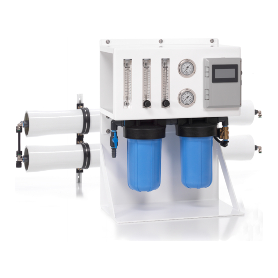
- Page 3 (modular mount). The pressure vessel set can be mounted horizontally or vertically, and includes mounting rails. An installation kit is included to supply hose and tubing and fittings. FCI WATERMAKERS, INC. General...
-
Page 4: General
& instructions for the installation, operation, maintenance, and troubleshooting for FCI Watermakers Desalination Systems. Anyone responsible for the installation, operation, and maintenance of a FCI Watermakers Desalination System must read and understand the contents of this manual, and comply with these instructions, guidelines, and safety requirements at all times. -
Page 5: Theory Of Operation
While running, the user adjusts the operating pressure with the reject flowmeter valve until the product output matches the rated output. Also, the user adjusts the recycle flowmeter valve until the recycle flow is approximately 50% of rated output. FCI WATERMAKERS, INC. General... -
Page 6: Limited Warranty
NOTE: Warranty registration is required to activate your warranty. Please be sure to fill out the registration included in this manual and provide a copy to FCI Watermakers, Inc. WARRANTY PERIOD The following items are covered under warranty for the periods designated:... - Page 7 FCI Watermakers, nor does the warranty extend to components on which the serial number has been removed, defaced or changed. FCI Watermakers reserves the right to make changes or improvements in its product, during subsequent production, without incurring the obligation to install such changes or improvements on previously manufactured equipment.
-
Page 8: Warranty Registration
WARRANTY REGISTRATION INSTRUCTIONS: At the time of purchase of the FCI Watermakers system, please complete the warranty information listed below. After completing this form, please make a copy and submit the copy using one of the options at the bottom of the page. -
Page 9: Copyright Notification
FCI Watermakers, Inc. and protected by U.S. and international copyright laws. All software used in the design and manufacture of a FCI Watermakers Reverse Osmosis Desalination System is the property of FCI Watermakers, Inc. and protected by U.S. and international copyright laws. -
Page 10: Fci Contact Information
FCI CONTACT INFORMATION If you have questions regarding your FCI Watermakers system or the contents of this manual, or if you need replacement parts, please do not hesitate to contact us immediately. Our hands-on technical support is always at your service. -
Page 11: Table Of Contents
ILLUSTRATED PARTS / DTS +SOLO ILLUSTRATED PARTS / PUMP & MOTOR ILLUSTRATED PARTS / PRESSURE GAUGES ILLUSTRATED PARTS / FLOW METERS ILLUSTRATED PARTS / ELECTRICAL ILLUSTRATED PARTS / FILTER ASSEMBLY ILLUSTRATED PARTS / PRESSURE VESSELS REVISION HISTORY REVISION HISTORY FCI WATERMAKERS, INC. General... -
Page 12: Table Of Figures
Figure 21: 1 PV for 2,000 GPD Rated Systems (P/N 93-5414) Figure 22: 2 PVs for 3,000 GPD Rated Systems (P/N 93-5415) TABLE OF TABLES Table 1: Specifications for Components Supplied by Installer Table 2: Hose, Tubing, Route & Description FCI WATERMAKERS, INC. General... -
Page 13: General Information
At FCI Watermakers, our commitment and attention to detail transcends beyond materials and construction. Things that are seemingly trivial are never overlooked. For instance, your system’s specifications formulate the Model Number. -
Page 14: Pre-Installation
The FCI Watermakers System is supplied with an installation kit which includes an assortment of hoses needed to install the system. Because of the various options with regard to location, some installations may require additional hose or wire. - Page 15 The connection lines must not be “kinked.” ACCESSIBILITY CAUTIONS: This is a simple rule. Install the system and its supporting components in an accessible manner. The panel must be accessible for operation of the system. FCI WATERMAKERS, INC. Pre-Installation...
- Page 16 R.O. membranes are not installed. If the R.O. membrane elements are not installed and you wish to install them at this time, contact FCI Watermakers, Inc. and supply us with your original purchase order number, FCI’s invoice number, and this system’s serial number.
-
Page 17: Component Identification
3. Installation Kit (93-5419) 2. Pressure Vessel Set 2,000 GPD Rated System (P/N 93-5414) - or - 3,000 GPD Rated System Pre-Installed Pressure Vessel Fittings (P/N 93-5415) Flow In Product Out Reject Out Figure 1: Component Identification FCI WATERMAKERS, INC. Pre-Installation... -
Page 18: Installation Kits
Hose Clamp #12 3/4"-1-1/4", SS Wrench, Filter, JB Housing (Qty 4, P/N 73-0485) (P/N 22-0036) Connector, Straight, PE, Black Manual, DTS +SOLO 1/2" MPT x 1/2" Tube (P/N 97-5420) (P/N 74-0446) Figure 2: Installation Kit (P/N 93-5419) FCI WATERMAKERS, INC. Pre-Installation... -
Page 19: Piping & Instrumentation Diagram
Legend Check Valve Ball Valve GAC Filter Bladder Tank 2 Way Solenoid Valve Flow Meter Product Water Ultraviolet Check Valve Pressure Gauge Tank Fresh Water Pump Pressure Switch Ship’s Supply Figure 3: Piping & Instrumentation Diagram FCI WATERMAKERS, INC. Pre-Installation... -
Page 20: Component Descriptions
Using 3rd party, Non-FCI components may void any and all FCI Watermakers Warranty. We only wish to help you enjoy the luxury of owning a FCI Desalinating System. Treat it properly by using only FCI supplied parts, recommended consumables, and authorized accessories. - Page 21 The 125psi tubing is used to connect the product out of the pressure vessel to the 125psi PE Tubing "product inlet" of the panel, the "product out" of the panel to product water tank. is dull black FCI WATERMAKERS, INC. Pre-Installation...
-
Page 22: Figure 5: Filter Assembly Features
The maximum allowed pressure of the dockwater source is 50 psi. If it is more, a pressure regulator must be installed. Contact FCI Watermakers for details. The outlet of the filter assembly is pre-connected to the panel. If you are using modular mount, you can reuse the fittings on the existing 1/2 inch PE tubing, and replace the tubing with a longer length. -
Page 23: Figure 6: Panel Assembly Features
Flow Electrical Enclosure: · Door Fastening Screws · Hinges Cable Grip Reject Flow (To feed power cable into Adjustment Feed from Filters electrical enclosure) Valve Recycle Flow Operating Adjustment Pressure Valve Figure 6: Panel Assembly Features FCI WATERMAKERS, INC. Pre-Installation... -
Page 24: Figure 7: Pressure Vessel Set Features
Pre-Installed Pressure Vessel Fittings Flow In (3/8 inch, 250psi PE Tubing) 2,000 GPD Rated System Product Out (3/8 inch, 125psi PE Tubing) (P/N 93-5414) Reject Out (3/8 inch, 250psi PE Tubing) Figure 7: Pressure Vessel Set Features FCI WATERMAKERS, INC. Pre-Installation... -
Page 25: Installation
DTS system. If installing by modular mount, the +SOLO solenoid cable may need to be replaced with a longer cable. INSTALLATION CHECKLIST After the installation is complete, use the list to double check the installation. FCI WATERMAKERS, INC. Installation... -
Page 26: Components Supplied By Installer
Table 1: Specifications for Components Supplied by Installer Connection Specification Dockwater source The FCI Watermakers System must receive an uninterrupted supply of feed water (50 psi maximum) without air Connection at dockwater source 3/4" hose barb Reject discharge 1/2"... -
Page 27: Dimensions, Weight & Footprints
· Quantity of 4 12.00 Dry Weight: 94 lbs / 42.6 Kg (approximately) ± 0.010 Units: inches Tolerances: ± 0.030 inches (unless otherwise specified) Ø .38 ± 0.010 20.75 ± 0.010 Figure 8: Dimensions - Stand for Deck Mount FCI WATERMAKERS, INC. Installation... -
Page 28: Figure 9: Dimensions - Wall Mount
Dry Weight: · 70 lbs / 31.8 Kg (approximately) 22.22 Allow 4" drop-down clearance below 23.42 filter bowls for replacing filter elements. Units: inches Tolerances: ± 0.010 inches (unless otherwise specified) Figure 9: Dimensions - Wall Mount FCI WATERMAKERS, INC. Installation... -
Page 29: Figure 10: Dimensions - Modular Mount
Recommended Mounting Hardware (included with filters): 2.95 · 5/16" x 1-1/2" Lag Bolt and 5/16 Flat Washer · Quantity of 8 Ø .28 Units: inches Tolerances: ± 0.010 inches (unless otherwise specified) Figure 10: Dimensions - Modular Mount FCI WATERMAKERS, INC. Installation... -
Page 30: Figure 11: Dimensions - Pressure Vessel Sets
· 2 Pressure Vessels: 40 lbs / 18.1 Kg (approximately) Units: inches Allow 40" clearance on either end of Pressure Vessel Tolerances: ± 0.030 inches (unless otherwise specified) to service membrane without dismounting. Figure 11: Dimensions - Pressure Vessel Sets FCI WATERMAKERS, INC. Installation... -
Page 31: General Connection Diagrams
Filters Sea Level Product Water Tank Dock Water Supply +SOLO Vessel Set (3,000 GPD) Install Reject Discharge Fitting Above Sea Level Panel Filters Sea Level Product Water Tank Dock Water Supply Figure 12: General Connection Diagram FCI WATERMAKERS, INC. Installation... -
Page 32: System Installation / Mounting
Additional tubing may be needed. Allow 40" on either side of vessel if you plan to service vessels in the future without dismounting. Mount the pressure vessel set with 1/4" lag bolts, quantity of four. FCI WATERMAKERS, INC. Installation... -
Page 33: System Installation / Plumbing
Pull on tube to verify fitting To remake connection: is secure. 1. Press release button and pull tube from fitting. Release Button 2. Remake connection. Grab Ring Figure 13: Proper Installation of Hose Ends and Fittings FCI WATERMAKERS, INC. Installation... -
Page 34: Table 2: Hose, Tubing, Route & Description
Above Sea Level NOTE: Use with 1/2 inch connector from Install Kit. 3/8 inch 125 psi PE Tubing Tube G Panel, "Product to Tank" Product Water Tank NOTE: Use with 3/8 inch connector from Install Kit. FCI WATERMAKERS, INC. Installation... -
Page 35: Figure 14: Plumbing Connections
· 3/8" 125psi PE Tubing Reject Out (Tube D) · Connects to Panel, "From Vessels" · 3/8" 250psi PE Tubing - or - 3,000 GPD Rated System (P/N 93-5414) 2,000 GPD Rated System (P/N 93-5414) Figure 14: Plumbing Connections FCI WATERMAKERS, INC. Installation... -
Page 36: System Installation / Electrical Connections
• Never attempt to hook-up or service this system without disconnecting all power. • Always check to make sure system voltage matches incoming voltage. • If system is 3-phase, be sure to check for correct rotation on all pumps before running system. FCI WATERMAKERS, INC. Installation... -
Page 37: Figure 15: Wiring The Power Supply
Otherwise, close and secure electrical enclosure door with its corner screws and proceed to "INSTALLATION CHECKLIST" on page 25. Single Phase 120/240 VAC 50/60 Hz Incoming Power: #1: Hot (Red) #2: Neutral/Hot (Black) #G: Ground (Green) Figure 15: Wiring the Power Supply FCI WATERMAKERS, INC. Installation... -
Page 38: Figure 16: Wiring The Solenoid (Modular Mount Only)
Refer to Figure 16. 3. Close and secure electrical enclosure door with its corner screws and proceed to "INSTALLATION CHECKLIST" on page 25. Inlet Solenoid Figure 16: Wiring the Solenoid (modular mount only) FCI WATERMAKERS, INC. Installation... -
Page 39: Schematics
SCHEMATICS 1 2 G FCI WATERMAKERS, INC. Installation... -
Page 40: Installation Checklist
• Electrical connections are secure • All Coast Guard/local codes have been met • No iron or ferrous fittings have been used • Electrical connections are correct • Plumbing connections do not leak • Hose clamps are tight FCI WATERMAKERS, INC. Installation... -
Page 41: Operational Instructions
Always try to maintain the pressure necessary for the system to operate at its rated output. As a safety feature, the system will shutdown when the pressure is too high or too low. FCI WATERMAKERS, INC. Operational Instructions... -
Page 42: Temperature & Pressure Effects Chart
1500 1400 1300 1200 1100 1000 9 10 11 12 13 14 15 16 17 18 19 20 21 22 23 24 25 26 27 28 ºC Figure 18: Water Temperature vs. Output (constant pressure) FCI WATERMAKERS, INC. Operational Instructions... -
Page 43: Operating The Dts
1. Check to be sure all Inlet/Discharge valves are open, fully open Reject Flow knob, fully close Recycle Flow knob, and check the main breaker is turned on. Display will show FCI Watermakers, press the water logo to proceed to home screen. 2. Press the Start button: The Low-Pressure Solenoid will engage and the display screen will indicate “Prime”... -
Page 44: R1 Roc Overview
This allows the user to be able to activate the screen even with gloves on, and allows for better overall screen design. FCI WATERMAKERS, INC. Operational Instructions... -
Page 45: Displays And Graphics
Setup – Displays the setup home screen which allows the user to change settings. Contact – Displays the contact screen. Direction Arrows – Allow the user to navigate through various screens. The arrows will be white in color when they can be pressed to show additional screens. FCI WATERMAKERS, INC. Operational Instructions... - Page 46 Gray – System is not active and in standby mode. Flashing Green – System is active, and is either priming or initializing. Green – System is active and running. Red – System is shutting down. FCI WATERMAKERS, INC. Operational Instructions...
-
Page 47: Display Screens
Clear – Press this button to clear the system after a shutdown has taken place. Stop – Press this button to stop the system. Navigation Bar – This allows the user to easily navigate between main screens. FCI WATERMAKERS, INC. Operational Instructions... - Page 48 Initialization – The initialization timer is the amount of time in seconds the initialization sequence will be active. Navigation Bar – This allows the user to easily navigate between main screens. Left Arrow – Goes back to the main setup screen. FCI WATERMAKERS, INC. Operational Instructions...
- Page 49 Navigation Bar – This allows the user to easily navigate between main screens. Left Arrow – Goes back to the main setup screen. Right Arrow – Goes to page #2 of service. FCI WATERMAKERS, INC. Operational Instructions...
- Page 50 Navigation Bar – This allows the user to easily navigate between main screens. Left Arrow – Goes back to the main setup screen. Right Arrow – Goes to page #2 of config. FCI WATERMAKERS, INC. Operational Instructions...
- Page 51 Left Arrow – Goes to page #2 of config. Contact The Contact Screen shows information on how the company can be contacted with any questions. Navigation Bar – This allows the user to easily navigate between main screens. FCI WATERMAKERS, INC. Operational Instructions...
-
Page 52: System Functionality
Clear – Press this button to clear the system once a shutdown has taken place. Stop – Press this button to stop the system. Navigation Bar – This allows the user to easily navigate between main screens. Right Arrow – When pressed, will proceed to the Initialize Sequence. FCI WATERMAKERS, INC. Operational Instructions... - Page 53 Clear – Press this button to clear the system once a shutdown has taken place. Stop – Press this button to stop the system. Navigation Bar – This allows the user to easily navigate between main screens. FCI WATERMAKERS, INC. Operational Instructions...
-
Page 54: System Alarms
Triggered when the system’s pressure reaches 3 psi. Clear Select the alarm, and clear the system. • High Pressure Shutdown Cause Triggered when the system’s pressure reaches 225 psi. Clear Select the alarm and clear the system. FCI WATERMAKERS, INC. Operational Instructions... -
Page 55: Maintenance & Repair
8. With the new membrane in hand, slide into the vessel in the same position as the original came out. 9. Inspect the o-rings, replace if needed, lubricate the o-rings and slide into the vessel. 10. Replace the fittings and hoses. FCI WATERMAKERS, INC. Maintenance & Repair... -
Page 56: Figure 20: Replacing The Membrane
1/2" MPT x 1/2" Tube (P/N 74-0455) Nipple, PVC, 3/8" CL (P/N 70-1895) Coupling, 3/8" TxT, PVC (P/N 70-0355) Elbow, 3/8" NPT x 3/8" Tube (P/N 71-5224) Figure 21: 1 PV for 2,000 GPD Rated Systems (P/N 93-5414) FCI WATERMAKERS, INC. Maintenance & Repair... -
Page 57: Figure 22: 2 Pvs For 3,000 Gpd Rated Systems (P/N 93-5415)
Tubing, 3/8" OD x .062 wall, 250 PSI (P/N 74-4261-4.75) Tee, PE, Black 1/2 MPT x 1/2" Tube (P/N 74-0465) Tubing, PE 1/2 (P/N 74-0474-4.25) Figure 22: 2 PVs for 3,000 GPD Rated Systems (P/N 93-5415) FCI WATERMAKERS, INC. Maintenance & Repair... -
Page 58: Storage And Winterizing Procedures
DO NOT subject the system to temperatures below 32º Fahrenheit (0º Celsius) unless the system has been rinsed with a solution of product water with twenty percent (20%) food-grade glycerin (propylene glycol). FCI WATERMAKERS, INC. Maintenance & Repair... -
Page 59: Parts
"ILLUSTRATED PARTS / PRESSURE GAUGES" on page 65 • "ILLUSTRATED PARTS / FLOW METERS" on page 67 • "ILLUSTRATED PARTS / ELECTRICAL" on page 70 • "ILLUSTRATED PARTS / FILTER ASSEMBLY" on page 72 • "ILLUSTRATED PARTS / PRESSURE VESSELS" on page 73 FCI WATERMAKERS, INC. Parts... -
Page 60: Illustrated Parts / Dts
ILLUSTRATED PARTS / DTS +SOLO FCI WATERMAKERS, INC. Parts... - Page 61 ILLUSTRATED PARTS / DTS +SOLO (continued) FCI WATERMAKERS, INC. Parts...
- Page 62 ILLUSTRATED PARTS / DTS +SOLO (continued) FCI WATERMAKERS, INC. Parts...
- Page 63 ILLUSTRATED PARTS / DTS +SOLO (continued) FCI WATERMAKERS, INC. Parts...
-
Page 64: Illustrated Parts / Pump & Motor
ILLUSTRATED PARTS / PUMP & MOTOR FCI WATERMAKERS, INC. Parts... -
Page 65: Illustrated Parts / Pressure Gauges
ILLUSTRATED PARTS / PRESSURE GAUGES FCI WATERMAKERS, INC. Parts... - Page 66 ILLUSTRATED PARTS / PRESSURE GAUGES (continued) FCI WATERMAKERS, INC. Parts...
-
Page 67: Illustrated Parts / Flow Meters
ILLUSTRATED PARTS / FLOW METERS FCI WATERMAKERS, INC. Parts... - Page 68 ILLUSTRATED PARTS / FLOW METERS (continued) FCI WATERMAKERS, INC. Parts...
- Page 69 ILLUSTRATED PARTS / FLOW METERS (continued) FCI WATERMAKERS, INC. Parts...
-
Page 70: Illustrated Parts / Electrical
ILLUSTRATED PARTS / ELECTRICAL FCI WATERMAKERS, INC. Parts... - Page 71 ILLUSTRATED PARTS / ELECTRICAL (continued) FCI WATERMAKERS, INC. Parts...
-
Page 72: Illustrated Parts / Filter Assembly
ILLUSTRATED PARTS / FILTER ASSEMBLY FCI WATERMAKERS, INC. Parts... -
Page 73: Illustrated Parts / Pressure Vessels
ILLUSTRATED PARTS / PRESSURE VESSELS FCI WATERMAKERS, INC. Parts... - Page 74 ILLUSTRATED PARTS / PRESSURE VESSELS (continued) FCI WATERMAKERS, INC. Parts...
- Page 75 ILLUSTRATED PARTS / PRESSURE VESSELS (continued) FCI WATERMAKERS, INC. Parts...
- Page 76 ILLUSTRATED PARTS / PRESSURE VESSELS (continued) FCI WATERMAKERS, INC. Parts...
-
Page 77: Revision History
REVISION HISTORY REVISION HISTORY Revision Date Description 02/15/2016 Initial release. 03/01/2017 Schematic and Illustrated Part 93-5372 updated. 02/09/2020 Filter wrench added to illustrations. FCI WATERMAKERS, INC. Revision History... - Page 78 NOTES FCI WATERMAKERS, INC. Revision History...
- Page 80 Document Part Number: 97-5420 Revision C 3782 W 2340 S, STE E | WEST VALLEY CITY, UT 84120-7291 | 801 906 8840 | fciwatermakers.com...
Need help?
Do you have a question about the DOCKSIDE TREATMENT SYSTEM PLUS Series and is the answer not in the manual?
Questions and answers