
Related Manuals for North Ridge Pumps Hose pump Series


Summary of Contents for North Ridge Pumps Hose pump Series
- Page 1 Hose pump series Bredel 25 and Bredel 32 Manual X-Cel House, Chrysalis Way, Langley Bridge, Eastwood, Nottinghamshire NG16 3RY Tel: +44 (0) 1773 302 660 | Email: sales@northridgepumps.com | Website: www.northridgepumps.com...
-
Page 2: Table Of Contents
CONTENTS GENERAL How to use this manual ................8 Original instructions ................8 Other supplied documentation ..............8 Service and support ................8 Environment and disposal of waste ............9 SAFETY Symbols ....................10 Intended use ..................10 Use in potentially explosive atmospheres ..........11 Responsibility .................. - Page 3 Inspection ..................... 21 Installation conditions ................21 5.3.1 Ambient conditions ..............21 5.3.2 Set-up ..................21 5.3.3 Pipework ................... 22 5.3.4 Frequency controller ..............23 Lifting and moving the pump ..............24 Placing the pump .................. 24 COMMISSIONING Preparations ..................25 Commissioning ..................
- Page 4 10.1.1 Performance ................56 10.1.2 Materials ..................57 10.1.3 Surface treatment ..............58 10.1.4 Lubricant table pump ..............58 10.1.5 Weights ..................59 10.1.6 Torque figures ................60 10.1.7 Shims specifications ..............61 10.2 Lubricant table gearbox ................ 62 10.3 Gearbox ....................
-
Page 5: General
GENERAL GENERAL How to use this manual This manual is intended as a reference book by means of which qualified users are able to install, commission and maintain the hose pumps mentioned on the front cover. Original instructions The original instructions for this manual have been written in English. -
Page 6: Environment And Disposal Of Waste
GENERAL Environment and disposal of waste CAUTION Always observe the local rules and regula- tions with respect to processing (non reus- able) parts of the hose pump. Enquire within your local government about the possibilities reuse environment-friendly processing of packaging materials, (contaminated) lubricant and oil. -
Page 7: Safety
SAFETY SAFETY Symbols In this manual the following symbols are used: WARNING Procedures which, if not carried out with the necessary care, may result in serious damage to the hose pump or in serious bodily harm. CAUTION Procedures which, if not carried out with the necessary care, may result in serious damage to the hose pump, the surrounding area or the environment. -
Page 8: Use In Potentially Explosive Atmospheres
SAFETY and function of the product. Observing the instructions in the user's documentation also belongs to intended use. Only use the pump in conformance with the intended use described above. The manufacturer cannot be held responsible for damage or harm resulting from use that is not in conformance with the intended use. -
Page 9: Qualification Of The User
SAFETY Qualification of the user The installation, use and maintenance of the hose pump should only be performed by well-trained and qualified users. Temporary staff and persons in training may use the hose pump only under the supervision and responsibility of trained and qualified users. Regulations and instructions •... -
Page 10: Warranty Conditions
WARRANTY CONDITIONS WARRANTY CONDITIONS The manufacturer offers a two-year warranty on all parts of the hose pump. This means that all parts will be repaired or replaced free of charge, with the exception of consumables, such as pump hoses, hose clamps, ball bearings, wear rings, and seals, or parts which have been misused or have been intentionally damaged. -
Page 11: Description
DESCRIPTION DESCRIPTION Identification of the product 4.1.1 Identification of the product The hose pump can be identified based on the identification plates or stickers on: Pump head Gearbox Electric motor Pump hose Frequency controller (option) 4.1.2 Identification of the pump The identification plate on the pump head contains the following data: Pump type... -
Page 12: Identification Of The Electric Motor
DESCRIPTION 4.1.4 Identification of the electric motor The identification plate on the electric motor contains the following data: Type number Serial number Article number Mains Frequency Speed Power Power factor Current 4.1.5 Identification of the frequency controller The identification of the Bredel Variable Frequency Drive (VFD) can be found inside the VFD. -
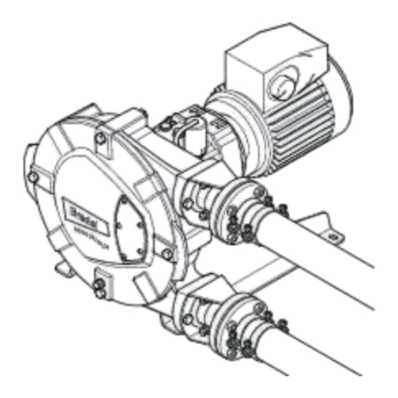
Page 13: Construction Of The Pump
DESCRIPTION Construction of the pump Pump hose Pump housing Rotor Pressing shoes Cover Support Gearbox Electric motor Adapter without motor (option) Frequency controller (option) -
Page 14: Operation Of The Pump
DESCRIPTION Operation of the pump The heart of the pump head consists of a specially constructed pump hose (A) which lies contorted against the inside of the pump housing (B). Both ends of the hose are connected to the suction and discharge lines by means of a flange construction (C). -
Page 15: Pump Hose
DESCRIPTION Pump hose 4.4.1 General Outer extruded layer made of natural rubber Four nylon reinforcement layers Inner extruded liner The pump hose liner material should be chemically resistant with the product to be pumped. Dependent on the specific requirements of your application a corresponding pump hose must be selected. -
Page 16: Hose Compression Force Adjustment (Shimming)
DESCRIPTION 4.4.2 Hose compression force adjustment (shimming) In order to achieve optimal life of the pump hose, the compression force of the pump hose can be adjusted by placing a number of shims under the pressing shoes. The shims (A) are fitted between the rotor (B) and the pressing shoe (C). -
Page 17: Electric Motor
DESCRIPTION Electric motor If the electric motor has been standard supplied by the manufacturer, it is an integrated standardized squirrel- cage motor. Refer to § 10.4 for specifications. If the pump used potentially explosive atmospheres, contact your Bredel representative. Motor frequency controller Refer to the also supplied documentation of the supplier and §... -
Page 18: Installation
INSTALLATION INSTALLATION Unpacking When unpacking carefully follow the instructions as given on the packaging or on the hose pump. Inspection Check that your delivery is correct and check it for any transport damage. Refer to § 4.1.1. Report any damage immediately to your Bredel representative. -
Page 19: Pipework
INSTALLATION 5.3.3 Pipework When determining connecting suction discharge lines consider the following points: • The bore size of the suction and discharge lines must be larger than the bore size of the pump hose. For more information consult your Bredel representative. -
Page 20: Frequency Controller
INSTALLATION Maximum permissible loads [N] on the pump flange Force Bredel 25 Bredel 32 5.3.4 Frequency controller WARNING A Bredel VFD that is fitted without the con- trol switch starts automatically when power is applied. If the hose pump is fitted with a Bredel Variable Frequency Drive (VFD), consider the following points: •... -
Page 21: Lifting And Moving The Pump
INSTALLATION Lifting and moving the pump For lifting and moving the pump head, it has been fitted with a lifting strip. This lifting strip (A) is fitted on the rear of the pump head. For the weights, refer to § 10.1.5. The complete hose pump, i.e. -
Page 22: Commissioning
COMMISSIONING COMMISSIONING Preparations WARNING A Bredel VFD that is fitted without the con- trol switch starts automatically when power is applied. WARNING Disconnect and lock the power supply to the pump drive before any work is carried out. In case the motor is fitted with a frequency controller and has a single-phase power supply, wait two minutes to make sure that the capacitors have discharged. -
Page 23: Commissioning
COMMISSIONING Commissioning Connect the pipework. Make sure that there are no obstructions such as closed valves. Switch on the hose pump. Check the rotation of the rotor. Check the capacity of the hose pump. If the capacity differs from your specification, follow the instructions in chapter or consult your Bredel representative. -
Page 24: Maintenance
MAINTENANCE MAINTENANCE General WARNING Disconnect and lock the power supply to the pump drive before any work is carried out. In case the motor is fitted with a frequency controller and has a single-phase power supply, wait two minutes to make sure that the capacitors have discharged. - Page 25 MAINTENANCE Point Action To be carried out Remark Check the lubricant Before startup of the Make sure that the lubri- level. pump and on a sched- cant level is above the uled interval during oper- minimum level line in the ation.
-
Page 26: Cleaning The Pump Hose
MAINTENANCE Point Action To be carried out Remark Replacing pressing Wear on the running sur- See § 7.7.1. shoes. face. Replacing bearings. If necessary. See § 7.7.2. In potentially explosive See § 7.7.1. atmospheres preventive Exclusively applicable in after 20,000 hrs. service potentially explosive or when damage is sus- atmospheres (Group II... - Page 27 MAINTENANCE The pump housing can be filled with lubricant via the breather/vent (A) on the rear of the pump housing. For this purpose remove the breather cap (B) and position a funnel (C) in the breather. In order to facilitate the filling with lubricant the breather cap (D) on the rear of the pump housing can be removed.
-
Page 28: Changing Oil In Gearbox
MAINTENANCE Changing oil in gearbox Isolate the pump from the electrical supply. Remove plug (A) and let the oil run out of the gearbox. The plug (A) is magnetically loaded. In this way metal particles in the oil are pulled to the plug. Clean the plug and remove any metal particles if necessary. - Page 29 MAINTENANCE Place a tray (A) under the drain plug in the bottom of the pump head. The tray must be large enough to contain the lubricant, possibly contaminated with product fluid, from the pump head. Remove the drain plug (B). Catch the lubricant from the pump housing in the tray.
- Page 30 MAINTENANCE Loosen the retaining bolts (A) of the flange bracket (B) and remove the bolts. Slide the flange bracket and the hose clip (C) off the hose. Carry out this procedure both for the inlet and outlet ports. Slide off the sealing ring (A). Check that the sealing ring is not deformed or damaged and replace it if necessary.
-
Page 31: Cleaning The Pump Head
MAINTENANCE 7.6.2 Cleaning the pump head Isolate the pump from the electrical supply. Remove the cover (B) by loosening the retaining bolts (A). Check the sealing ring (C) and replace it if necessary. Rinse the pump head with clean water and remove all residues. - Page 32 MAINTENANCE Fit the pump hose (A) via one of the ports. Let the motor run to pull the hose in the pump housing. The rotor will take up the hose. Stop the motor when the hose sticks out equally from both sides of the pump housing.
- Page 33 MAINTENANCE Slide insert (B) in flange (A) and press the insert in the hose. If necessary lubricate the insert with Bredel Genuine Hose Lubricant in order to simplify mounting. Make sure that the holes in flange (A) are aligned with the holes in flange bracket (C).
-
Page 34: Exchanging Replacement Parts
MAINTENANCE Connect the suction and discharge lines (B) and fit the retaining bolts (A). Tighten the retaining bolts with the correct torque. Refer to § 10.1.6. Exchanging replacement parts 7.7.1 Replacing pressing shoes Jog the motor until the pressing shoe (B) is positioned between the inlet and outlet port (A). - Page 35 MAINTENANCE Remove the cover (A) by loosening the four retaining bolts (B). Loosen the retaining bolt (A) of the pressing shoe (B) and remove the shoe. Remove the shims (C) if present. Fit the removed shims (C) again. Position the (new) pressing shoe (B), check that the Nord- ®...
-
Page 36: Replacing Seal Ring, Bearings And Wear Ring
MAINTENANCE Isolate the pump from the electrical supply. Repeat the procedure for removing and fitting this second pressing shoe by repeating steps 4 through 8. Refill the lubricant. Refer to § 7.4. 7.7.2 Replacing seal ring, bearings and wear ring Remove the pump hose. - Page 37 MAINTENANCE Use two crow bars to remove rotor (A). Position both crow bars behind the recesses (B) in the rotor and push the rotor from the hub. Dismount the retaining circlip (A) with the correct tool. Dismount the bearings (A) with the correct tool, the spacer ring (B) and the retaining circlip (C).
- Page 38 MAINTENANCE Fit a new seal (A) using good engineering practises. The seal must be fitted in the correct orientation (B). Make sure that the open side points to the pump cover. Support the rotor with wooden blocks at 90° to the spokes, with the ring (A) facing down.
- Page 39 MAINTENANCE Mount the retaining circlip (A). Fit rotor (A). The rotor is placed on the bearings with a loose fit. Press the rotor on the hub until it sticks. Fit the removed shims (C) again. Position the (new) pressing shoe (B), check that the Nord- ®...
-
Page 40: Adjusting Hose Compression Force (Shimming)
MAINTENANCE Adjusting hose compression force (shimming) Remove the pump cover before fitting and removing shims. In order to determine the correct number of shims for your specific application refer to § 10.1.7. CAUTION Too many shims, this means a too high compression force on the pump hose, will create a too high load on the pump head and pump hose, which may result in a... - Page 41 MAINTENANCE Place a tray (A) under the drain plug in the cover of the pump. Remove the drain plug (B). Catch the lubricant from the pump housing in the tray. Position the drain plug and tighten it firmly. Remove the cover (B) by loosening the retaining bolts (A).
-
Page 42: Fitting Options
MAINTENANCE Isolate the pump from the electrical supply. Repeat the procedure for this pressing shoe by repeating steps 4, 5, 6 and 7. Refill the lubricant via the breather. Refer to § 7.4. Fitting options 7.9.1 Fitting a high-level float switch Dismount the standard breather (B) on the rear of the pump, by dismounting it from crimp connector (A). - Page 43 MAINTENANCE Mount the breather (B) on the rear of the pump, by mounting it on crimp connector (A). Connect the high-level float switch to the auxiliary power circuit via the 2-metre long PVC cable (2 x 0.34 mm ). Bear in mind that the electrical contact of the float switch is normally closed (NC).
-
Page 44: Fitting A High And Low Level Float Switch
MAINTENANCE 7.9.2 Fitting a high and low level float switch For specifications, refer to § 7.9.1. If the pump is filled with lubricant this must be removed first. Place a tray (A) under the drain plug in the cover of the pump. Remove the drain plug (B). -
Page 45: Replacing The Revolution Counter
MAINTENANCE 7.9.3 Replacing the revolution counter Fit the inductive sensor (A) in stop (B) and adjust it to dimension "X" as indicated in the table below. Tighten the adjusting nuts with a torque of 25 Nm. Dimension "X" ± 0.1 mm Bredel 25 Bredel 32 26 mm... - Page 46 MAINTENANCE Specifications Voltage: 10...30 VDC Current: Max. 150 mA For use in non-explosive atmospheres Make sure the lubricant returns to the prescribed level. Refer to § 7.4.
-
Page 47: Storage
STORAGE STORAGE Hose pump • Store the hose pump or pump parts in a dry area. Make sure that the hose pump or pump parts are not exposed to temperatures lower than -40 °C or higher than +70 °C. • Cover the openings of the inlet and outlet ports. -
Page 48: Troubleshooting
TROUBLESHOOTING TROUBLESHOOTING WARNING Disconnect and lock the power supply to the pump drive before any work is carried out. In case the motor is fitted with a frequency controller and has a single- phase power supply, wait two minutes to make sure that the capacitors have discharged. - Page 49 TROUBLESHOOTING Problem Possible cause Correction High pump temperature. Non standard hose lubri- Consult the Bredel repre- cant used. sentative for the correct lubricant. Low lubricant level. Add Bredel Genuine Hose Lubricant. For the required amount of lubricant refer to § 10.1.4. Product temperature too Consult the Bredel repre- high.
- Page 50 TROUBLESHOOTING Problem Possible cause Correction Low capacity / pressure. Shut-off valve in the suc- Fully open the shut-off tion line (partly) closed. valve. Under shimming of the Consult the diagram in pressing shoes. § 10.1.7. Fit the correct number of shims. Hose rupture or badly worn Replace hose.
- Page 51 TROUBLESHOOTING Problem Possible cause Correction Vibration of the pump Suction and discharge Check and secure pipe- and pipework. lines are not secured cor- work. rectly. High pump speed with long Reduce pump speed. suction and discharge lines Reduce the line lengths on or high relative density or a both suction and dis- combination of these fac-...
- Page 52 TROUBLESHOOTING Problem Possible cause Correction Hose pulled into the Insufficient or no hose Add extra lubricant. Refer pump. lubricant in the pump head. to § 7.4. Incorrect lubricant: no Consult the Bredel repre- Bredel Genuine Hose sentative for the correct Lubricant in the pump lubricant.
-
Page 53: Specifications
SPECIFICATIONS SPECIFICATIONS 10.1 Pump head 10.1.1 Performance Description Bredel 25 Bredel 32 Max. capacity, continuous [m 1.80 3.25 Max. capacity, intermittent [m 2.88 5.25 Capacity per revolution [l/rev] 0.300 0.625 Max. permissible working pressure [kPa] 1600 Permissible ambient temperature [°C] -20 to +45 Permissible product temperature [°C] -10 to +80... -
Page 54: Materials
SPECIFICATIONS 10.1.2 Materials Description Material Pump housing Cast-iron Cover Cast-iron Pump rotor Cast-iron Pressing shoe Aluminium Pump support Mild steel, galvanised Flange bracket Mild steel, galvanised Mounting material of pump cover Mild steel, galvanised Mounting material of drive system Mild steel, galvanised Mounting material of pump support Mild steel, galvanised Seals... -
Page 55: Surface Treatment
SPECIFICATIONS 10.1.3 Surface treatment • After surface preparation, one layer of two-component acrylate is used for surface protection. Standard colour is RAL 3011, however other colours are optional. Contact your Bredel representative for details on surface treatment. • All galvanised parts have been provided with an electrolytic zinc layer of 15 - 20 microns. -
Page 56: Weights
SPECIFICATIONS 10.1.5 Weights Description Weight [kg] Bredel 25 Bredel 32 Pump head 58.5 Flange connection (2x), without inserts 3.72 5.52 Stainless steel insert (2x) 0.26 0.36 Hose Lubricant Sub total pump head 47.5 71.8 Pump support Mounting material TWK pump head Gearbox (model B3-B5) 15.5 Electric motor... -
Page 57: Torque Figures
SPECIFICATIONS 10.1.6 Torque figures Description Torques [Nm] Bredel 25 Bredel 32 Pressing shoe Cover Hose clamp Flange bracket Support Gearbox... -
Page 58: Shims Specifications
SPECIFICATIONS 10.1.7 Shims specifications • When the product temperatures are above 60 °C always use one shim less than indicated in the diagrams. • Always round up the number of shims. -
Page 59: Lubricant Table Gearbox
SPECIFICATIONS 10.2 Lubricant table gearbox Below is an overview of some of the recommended lubricants for the co-axial gearbox. In the majority of the cases, a mineral oil ISO VG 220 is recommended. In case of extreme ambient temperatures or a relatively wide range of ambient temperatures, a synthetic oil is recommended. -
Page 60: Gearbox
SPECIFICATIONS Recommended lubricants for the Bredel co-axial gearboxes Shell Shell Cassida Fluid GL Klüber Klüber-Summit HySyn Klüber oil 4UH1-460 Klüberbio CA2-460 FG32 Aral Aral Eural Gear 460 Aral Degol BAB 460 Texaco Cetus PAO 46 Optimol Optileb GT 460 Optisynt BS460 For a complete overview of the recommended lubricants contact your Bredel representa- tive. -
Page 61: Frequency Controller
SPECIFICATIONS 10.5 Frequency controller The frequency controller has been preprogrammed and only needs to be connected to the mains. RFI filter Integrated RFI filter B (industrial applications). Control Rotary knob for setting the speed and the keys for starting forward, stop and starting reverse. Protection class IP65 Mains power supply... -
Page 62: Parts List
SPECIFICATIONS 10.6 Parts list 10.6.1 Overview Pos. Description Cover assembly. Refer to § 10.6.2. Rotor assembly. Refer to § 10.6.3. Pump housing assembly. Refer to § 10.6.4. Pump support assembly. Refer to § 10.6.5. Flange assembly. Refer to § 10.6.6. Lubricant. -
Page 63: Cover Assembly
SPECIFICATIONS 10.6.2 Cover assembly Pos. Qty. Description Product codes for parts of pump type Bredel 25 Bredel 32 Bolt, hex. head F101058 F101058 Washer F322013 F322013 Sticker 225238 232238 Cover 225102 232102 Quad ring 225123 232123 Gasket F342019 F342019 Drain cap F911502 F911502 Gasket... -
Page 64: Rotor Assembly
SPECIFICATIONS 10.6.3 Rotor assembly Pos. Qty. Description Product codes for parts of pump type Bredel 25 Bredel 32 Pressing shoe 225110 232110 Shim 225107 232107 Spiral clamping bush F415084 F415084 Bolt, hex. head F101060 F101060 Nord-Lock ring F349006 F349006 Sealing cap S417007 S417007 Rotor... -
Page 65: Pump Housing Assembly
SPECIFICATIONS 10.6.4 Pump housing assembly Pos. Qty. Description Product codes for parts of pump type Bredel 25 Bredel 32 025020 032020 025040 032040 025070 032070 EPDM 025075 032075 Pump housing 225101 232101 Lifting strip 29065361 29065361 Washer, Spring Lock F336012 F336012 Bolt F111096... -
Page 66: Support Assembly
SPECIFICATIONS Pos. Qty. Description Product codes for parts of pump type Bredel 25 Bredel 32 Bearing B141260 B141260 Retaining circlip 29095297 29095297 Spacer ring 29085201 29085201 Retaining circlip F343049 F343049 10.6.5 Support assembly Pos. Qty. Description Product codes for parts of pump type Bredel 25 Bredel 32 Bolt... -
Page 67: Flange Assembly
SPECIFICATIONS 10.6.6 Flange assembly Pos. Qty. Description Product codes for parts of pump type Bredel 25 Bredel 32 O-ring S112231 S112271 Flange bracket, Steel 225197 232197 Flange bracket, SS 225197A 232197A Washer, Spring Lock F336012 F336012 Bolt F111096 F111096 Hose clamp C122004 C121006 Flange, DIN Steel... -
Page 68: Revolution Counter Assembly
SPECIFICATIONS 10.6.7 Revolution counter assembly Pos. Qty. Description Product codes for parts of pump type Bredel 25 Bredel 32 Gasket F342027 F342027 Revolution counter 29040462 29040462 Adapter 29027248 29027248 10.6.8 Lubricant Pos. Qty. Description Product codes for parts of pump type Bredel 25 Bredel 32 2 l can Bredel Genuine...
Need help?
Do you have a question about the Hose pump Series and is the answer not in the manual?
Questions and answers