Table of Contents
Advertisement
Advertisement
Table of Contents

Related Manuals for Perform Better PB Extreme Rower

Summary of Contents for Perform Better PB Extreme Rower
- Page 1 OWNER’S MANUAL Product May Vary Slightly From Pictured. ITEM NO.: 2014-01...
-
Page 2: Table Of Contents
TABLE OF CONTENTS Safety Instructions ........2 Storage ............19 Before You Begin ........3 Product Parts Drawing ....... 20 Equipment Warning, Warning Labels……...4 Parts List ............. 21 Hardware Identification Chart ....5 Assembly Instructions ......6 Computer Instructions ....... 11 Operational Instructions ......16 Maintenance ..........17 SAFETY INSTRUCTIONS... -
Page 3: Before You Begin
BEFORE YOU BEGIN convenient and simple method to begin your Thank you for choosing the ROWER. We take journey of getting your body in shape and achieving great pride in producing this quality product and a happier and healthier lifestyle. hope it will provide many hours of quality exercise Before reading further, please review the to make you feel better, look better, and enjoy... -
Page 4: Equipment Warning, Warning Labels
EQUIPMENT WARNING, WARNING LABELS This chart is provided to help identify the warning, caution, and notice labels on the ROWER. Please take a moment to familiarize yourself with all of the warning, caution, and notice labels. Label is larger than actual size WARNING LABEL... -
Page 5: Hardware Identification Chart
HARDWARE IDENTIFICATION CHART This chart is provided to help identify the fasteners used in the assembly process. Place the washers or the ends of the bolts or screws on the circles to check for the correct diameter. Use the small scale to check the length of the bolts and screws. -
Page 6: Assembly Instructions
ASSEMBLY INSTRUCTIONS ASSEMBLY INSTRUCTIONS STEP 1 First, take out the packing materials Styrofoam (A) and Styrofoam (B). Then flip them over so the sides with carved letter are facing up. Take the Main Frame (1) out from the carton and put it on both Styrofoam (A &... - Page 7 ASSEMBLY INSTRUCTIONS STEP 2 Turn the main assembly of the ROWER upside down and place it in the packing material Styrofoam (A & B) to avoid damage of housing. Attach Left and Right Support Legs (7 & 8) to the Main Frame (1) using: 4 PCs of M8x12mm Socket Head Cap Screw (81) and M8 Flat Washer (79).
- Page 8 ASSEMBLY INSTRUCTIONS STEP 4 Lift up the Main Frame (1) and Rail Frame (2) to insert the Rail Frame (2) into the Main Frame (1). Make the Shaft (24) on the Main Frame (1) fit into the gap in the Rail Frame (2). Then put the Main Frame (1) and Rail Frame (2) down.
- Page 9 ASSEMBLY INSTRUCTIONS STEP 6 Attach Pedal Support Plates (5) to the Main Frame (1) using: M8X160mm Socket Head Cap Screw (84) and Foot Pedal End Cap (9). NOTE: Fully tighten bolts at end of this step.
- Page 10 COMPUTER INSTRUCTIONS STEP 7 Attach Cell Phone Bracket (20) to the Console Monitor (19) using Rubber Band (21). STEP 8 Attach the Console Monitor (19) to the Console Mounting Bracket (69) using:1 PC of M8X75mm Button Head Cap Screw (78), M8 Flat Washer (79), and M8 Nylon Lock Nut (80). STEP 9 Connect Sensor Cable (23) into the back of the Console Monitor (19a).
-
Page 11: Computer Instructions
COMPUTER INSTRUCTIONS COMPUTER INSTRUCTIONS Your ROWER utilizes an air fan system to create resistance for your workout. We recommend that you use this computer console to vary your workout from session to session and note your progress toward your fitness goals. When used regularly in this way, the computer console can become an important source of motivation and interest which will help keep you on track. - Page 12 COMPUTER INSTRUCTIONS (DOWN BUTTON): Press to decrease the preset values. Press the button and hold it down, the presetting value will go faster, release the button to stop. BACK BUTTON: When selecting the programs, press the button to return to the previous program. When you finish a running program, press the button to jump into the IDEL mode.
- Page 13 COMPUTER INSTRUCTIONS CALORIES: Display range: 0 ~ 999 cals. Display flashing “100” for presetting CALORIES (countdown) program. The target calories value can be set from 10 to 999 cals. PADDLE WIDTH: Display range: 0 ~ 99 meters (or 0 ~ 304 feets). Display the distance each stroke can reach.
- Page 14 COMPUTER INSTRUCTIONS For Quick Start and all three countdown programs, press “SELECT” button to choose the data displayed in the same display window, including Time & Time/500m AVG. For the other seven programs, press “BACK” button to enter IDLE mode. Or press and hold “ENTER/STOP”...
- Page 15 COMPUTER INSTRUCTIONS 10/20 INTERVAL PROGRAM When it is in the “10/20 INTERVAL” program, the console monitor will display flashing “8” for presetting value of cycle. Then user can user “UP” and “DOWN” buttons to input the value from 1 to 99. User will workout for 10 seconds and then rest for 20 seconds.
-
Page 16: Operational Instructions
OPERATIONAL INSTRUCTIONS LOAD ADJUSTMENT There is a Damper (42) built into the Right Fan Shroud (43). Move the Indicator in the Damper (42) to point to the numbers on the Right Fan Shroud (43) to adjust the load. There are settings from 1 to 9. -
Page 17: Maintenance
OPERATIONAL INSTRUCTIONS USING THE CELL PHONE BRACKET The Cell Phone Bracket (20) can move up and down. Move up the Cell Phone Bracket (20), then slide the Cell Phone into the gap between the Cell Phone Bracket (20) and the Console Monitor (19). - Page 18 MAINTENANCE BUNGEE CORD ADJUSTMENT Over time, about 250,000 strokes on Handlebar (3), your Bungee Cord (38) may stretch. Follow the following process to adjust: 1. Position the Main Frame Assembly (1) as shown in the illustration. Remove the Main Frame Top Cap (68) from the Main Frame (1). Slide out the Bottom Cover (70) from the Main Frame (1).
-
Page 19: Storage
STORAGE 1. To store the ROWER, simply keep it in a clean dry place. 2. To avoid damage to the electronics, remove the batteries from the Console Monitor (19) before storing the ROWER for one year or more. 3. Move the ROWER with the Transport Wheels (66) on the Front Stabilizer (4). Lift the Rear Stand of the Rail Frame (2) to move the ROWER. -
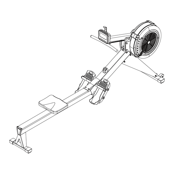
Page 20: Product Parts Drawing
PRODUCT PARTS DRAWING FRONT 31 29 BACK... -
Page 21: Parts List
PARTS LIST PART# DESCRIPTION Main Frame Rail Frame Handlebar Front Stabilizer Pedal Support Plate Console Monitor Post Left Support Leg Right Support Leg Foot Pedal End Cap Seat Carriage Bungee Cord Hook Chain Bracket Stainless Steel Rail Perforated Steel Mesh ø... - Page 22 U Bolt Inner Spacer Outer Collar Bearing 6003RS Bearing 608ZZ Bearing 6201RS One Way Bearing HF2016 Chain Sprocket Bungee Cord Bungee Cord Pulley Chaing Roller Bearing 6000ZZ Damper Right Fan Shroud Left Fan Shroud Foot Pedal Foot Pedal Holder Pedal Strap ø...
- Page 23 Bushing 6001 Bushing 6003 Guide Roller Seat Roller Roller Sleeve Transport Wheel Rail End Cap Main Frame Top Cap Console Mounting Bracket Bottom Cover ø ø Plastic Washer, 10.2x 14x1mm Phillips Head Screw, M6x10mm Lock Washer, Internal Tooth M6 Nylon Lock Nut, M6 Phillips Head Screw, ST4.2x10mm Flat Washer, M6 Socket Head Cap Screw, M8x65mm...
- Page 24 Elastic Ring Nylon Lock Nut, M10 Phillips Head Screw, ST4.2x6mm Phillips Head Screw, M4x45mm Hex Nut, M4 Pull Pin Socket Head Cap Screw, M6x16mm Phillips Head Screw, M6x30mm Phillips Head Screw, M6x10mm Screwdriver Allen Wrench, 6mm Wrench Hex Nut, M6 PU Spacer Plug Bearing, 6001RS...
Need help?
Do you have a question about the PB Extreme Rower and is the answer not in the manual?
Questions and answers