Table of Contents
Advertisement
Advertisement
Table of Contents

Related Manuals for Grundfos CU 323 Series


Summary of Contents for Grundfos CU 323 Series
- Page 1 GRUNDFOS INSTRUCTIONS CU 323 Installation and operating instructions...
-
Page 2: Table Of Contents
English (GB) Installation and operating instructions 1. General information Original installation and operating instructions These installation and operation instructions describe Grundfos CU 323. 1.1 Target group Sections 1-2 give the information necessary to be These installation and operating instructions are able to install the product in a safe way. -
Page 3: Installing The Product
CU 323 must not be installed in potentially explosive CU 323 is only intended for factory wiring. environments, but may be used together with Before installing the product, check the following: Grundfos pumps approved for installation in • CU 323 corresponds to the order. potentially explosive environments. -
Page 4: Electrical Installation
CIM 500 Modbus TCP, Profinet or BACnet IP. The CIM modules must be ordered separately. The installation of the CIM module is described in the Hydro Multi-B service instructions available in Grundfos Product Center. Copy the link below to see the document online: http://net.grundfos.com/qr/i/97916525. -
Page 5: Product Introduction
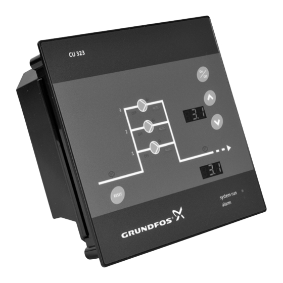
3. Product introduction 3.1 Product description The CU 323 control unit is designed for the monitoring and control of up to four pumps. 3.2 User interface CU 323 AUTO AUTO AUTO AUTO RESET System run system run Alarm alarm Fig. 5 CU 323 user interface Pos. - Page 6 Pos. Display Description Shows the setpoint. "Setpoint" After unlocking CU 323, the setpoint will flash. Proportional pressure control. "PPP" will be flashing for one second followed by the current setpoint for four seconds. This function is only available for E-pump systems. 1___! The tank symbol appears in tank-filling mode with float switches.
- Page 7 Indicator Pos. Status Description light Normal state. Water shortage. Normal state. Fault, primary sensor and/or redundant sensor. The maximum outlet pressure or the level limit has been exceeded. The pump has stopped due to cascade operation. The system is in "OFF" state. The power supply has been switched off.
-
Page 8: Layout Of The Back Of Cu 323
3.3 Layout of the back of CU 323 3.4 Identification 3.4.1 Nameplate CU 323 can be identified by means of the nameplate on the back. See fig. 7. 100-240 Vac 50/60 Hz - Max. 18W Fig. 7 Nameplate Pos. Description Fig. -
Page 9: Control Functions
4. Control functions 4.1 Functions of indicator lights and relays System indicator lights Operating Alarm Description "System run" "Alarm" relay relay (green) (red) The power supply has been switched off. C NO NC C NO NC Permanently The system is in normal operation, and one or several pumps are running. -
Page 10: Operating The Product
5. Operating the product User operation depends on the system mode. The system modes are described in the following sections. Read this document before startup. Installation and operation must comply with local regulations and accepted codes of good practice. 5.1 Local mode, external stop not activated In this mode, the system is locally controlled, and the external stop via digital input is not activated. -
Page 11: Remote-Controlled, External Stop Not Activated
Stopping and starting the system Stopping the system E.st Starting the system If you do not touch the buttons for three seconds, CU 323 reverts to the initial display. Changing the setpoint Changing the setpoint E.st If you do not touch the buttons for three seconds, CU 323 reverts to the initial display. -
Page 12: Remote-Controlled, External Stop Activated
5.4 Remote-controlled, external stop activated In this mode, the system is remote-controlled, and the external stop via digital input is activated. If you want to change the local settings, follow the flow chart examples below. Keep the buttons pressed for three seconds. See section 5.2 Local mode, external stop... -
Page 13: Servicing The Product
Activating the function via PC Tool E-products Settings > Primary controller. 1. Select: Enabled proportional pressure. 2. Set: Influence at zero flow. 3. Set: Filter factor. 4. Select: Hmax / Enter value. Based on pump data. 5. Select: Qnom / Enter value. Based on pump data. 6. -
Page 14: Fault Finding The Product
The main switch has cut out. Cut in the main switch. The main switch is defective. Replace the main switch. The motor protection has been Contact Grundfos. activated. The motor is defective. Repair or replace the motor. The pressure transmitter is Replace the pressure transmitter. - Page 15 Fault Possible cause Remedy The pumps are The valves are closed. Open the valves. running, but deliver The inlet pipe or pumps are no water. Clean the inlet pipe or pumps. blocked by impurities. The non-return valve is blocked Clean the non-return valve. Check that in the closed position.
-
Page 16: Technical Data
8. Technical data 8.3.4 Digital inputs Transient voltages typically present on the mains Open-circuit voltage 24 VDC supply are category 2. Closed-circuit current 5 mA, DC 8.1 Operating conditions Frequency range 0-4 Hz Altitude above sea level 8.3.5 Analog inputs Maximum 2000 m. - Page 17 8.3.10 Terminal groups Fig. 10 Terminal groups The terminals of the groups 4, 6 and 7 are insulated from all other terminal groups by reinforced insulation, 2224 VAC. Group Description Connection of power supply Internal GENIbus connection Fieldbus connection for CIM module (optional) Input for PTC sensor or thermal switch Analog inputs...
-
Page 18: Overview Of Inputs And Outputs
8.4 Overview of inputs and outputs Legend Abbreviation Description Analog input Common Digital input Digital output Normally closed contact Normally open contact Positive temperature coefficient Relay output For position numbers, see fig. 10. Pos. Terminal Designation Data Diagram Connection to CU 323 phase conductor 1 x 100-240 VAC ±... -
Page 19: Dimensions
1. Use the public or private waste collection service. 2. If this is not possible, contact the nearest Grundfos company or service workshop. The crossed-out wheelie bin symbol on a product means that it must be disposed of separately from household waste. - Page 20 Declaration of conformity GB: EU declaration of conformity BG: Декларация за съответствие на EO We, Grundfos, declare under our sole responsibility that the products Ние, фирма Grundfos, заявяваме с пълна отговорност, че CU323, CU352, CU354, CU362, CU372, to which the declaration продуктите...
- Page 21 VI: Tuyên bố tuân thủ EU AL: Deklara e konformitetit të BE Chúng tôi, Grundfos, tuyên bố trong phạm vi trách nhiệm duy nhất Ne, Grundfos, deklarojmë vetëm nën përgjegjësinë tonë se produktet của mình rằng sản phẩm CU323, CU352, CU354, CU362, CU372 mà...
- Page 22 Appendix 中国 RoHS...
- Page 24 Argentina China Hong Kong Bombas GRUNDFOS de Argentina S.A. GRUNDFOS Pumps (Shanghai) Co. Ltd. GRUNDFOS Pumps (Hong Kong) Ltd. Ruta Panamericana km. 37.500 Centro 10F The Hub, No. 33 Suhong Road Unit 1, Ground floor Industrial Garin Minhang District Siu Wai Industrial Centre 1619 Garín Pcia.
- Page 25 Malaysia Serbia Turkey GRUNDFOS Pumps Sdn. Bhd. Grundfos Srbija d.o.o. GRUNDFOS POMPA San. ve Tic. Ltd. 7 Jalan Peguam U1/25 Omladinskih brigada 90b Sti. Glenmarie Industrial Park 11070 Novi Beograd Gebze Organize Sanayi Bölgesi 40150 Shah Alam Phone: +381 11 2258 740...
- Page 26 97775216 1219 ECM: 1273606 www.grundfos.com...
Need help?
Do you have a question about the CU 323 Series and is the answer not in the manual?
Questions and answers