Table of Contents
Advertisement
Advertisement
Table of Contents

Subscribe to Our Youtube Channel
Related Manuals for Topcon IS-5000

Summary of Contents for Topcon IS-5000
- Page 1 IS-5000 INSTRUMENT STAND...
- Page 2 SAFETY CONCERNS The IS-5000 Stand conforms to UL 60601-1 and CSA C22.2 No. 601.1-M90. Any of the optional equipment defined in this manual can be added to the IS-5000 without introducing any additional safety hazards.
-
Page 3: Table Of Contents
TABLE OF CONTENTS NOMENCLATURE .................... 1 IS-5000 Instrument Stand Main Components ................ 1 PERFORMANCE & SPECIFICATIONS ............2 ASSEMBLY ......................3 Tools ............................3 Instrument Stand ........................3 ... -
Page 4: Nomenclature
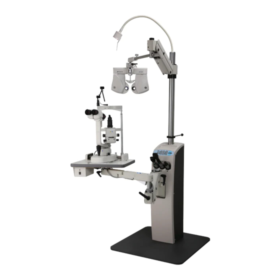
1. NOMENCLATURE 1.1 IS-5000 Instrument Stand Main Components Figure 1 shows the primary components and key features of the IS-5000 Instrument Stand. Use this figure as a reference. Overhead Lamp Refractor Arm Pole Control Panel Base Assembly Slit Lamp Arm... -
Page 5: Performance & Specifications
2. PERFORMANCE & SPECIFICATIONS Instrument Stand Base Size: 25.5 inch x 27.0 inch (648 mm x 686 mm) Stand Size: 8.0 inch x 10.0 inch x 34.0 inch (203 mm x 254 mm x 864 mm) Mode of Operation: Continuous Use (Class 1 protection) Counterbalanced Refractor Arm ... -
Page 6: Assembly
Hex wrench sizes 3/16, 5/32, 1/8, 3/32 (included in accessory kit). 3.2 Instrument Stand Unpack the IS-5000 and allow the unit to come to room temperature. The standard components of the Instrument Stand are as follows: base unit, pole, refractor arm, and accessory box. - Page 7 Set the refractor arm to the proper height. See Figure 3.2 for the suggested optimum mounting location. The arm maybe moved to accommodate user comfort by loosening the set screws, moving the arm to the desired position, then re- tightening the set screws securely. Figure 3.2: Instrument arm mounting locations Optional: Attach the chart projector arm into position on the pole and secure in place.
- Page 8 (NOTE: Using a non-Topcon chair may require an adapter; see Table 1 for pin functionality. The chair supplies AC power to the IS-5000, and the IS-5000 acts as a switch and returns the power to the chair to make it go up and down.)
-
Page 9: Installing Instruments
The wells are wired at the factory at 3.5 volts DC. 3.3.4 Chart Projector (optional) The chart projector may be mounted on the wall or on the IS-5000. If it is mounted on the IS-5000, the chart projector arm supports any automatic chart projector. The arm has a 0.75-inch diameter socket for mounting a projector. -
Page 10: Power Up
Final adjustments will be performed in Section 5: Adjustments. Once satisfied with the connections of all the instruments, install the back cover of the IS-5000. To install the removable back shroud cover, carefully push the cover forward into place and securely install the seven (7) Phillips screws. -
Page 11: System Operation
4.5 Auxiliary Receptacle Button The auxiliary buttons, AUX 1 & 2, control the power to the auxiliary receptacles located to the right of the circuit board assembly inside the IS-5000. These receptacles are recommended for chart projector or any other desired equipment connections. -
Page 12: Adjustments
5. ADJUSTMENTS The refractor arm may require adjustment depending upon the weight of the instrument in use. NOTE: Vertical adjustments in Section 5.1.2 to 5.1.3 are for Refractor arm or an additional 3 arm only. No vertical brake adjustment is required for Slit Lamp arm. 5.1 Refractor and Slit Lamp Arm 5.1.1 Counterbalance Adjustment To adjust the counterbalancing of the instrument arm, remove the black plastic panel... -
Page 13: Drift Elimination
If the resistance is inadequate, repeat the above procedure and turn the small Hex screw another 1/4 turn.) 5.1.4 Drift Elimination Occasionally during regular use the arms may tend to drift slightly. Increasing the drag on the arm will eliminate a slight drift. Drag is adjusted by turning the larger of the two (2) set screws located at both ends of the arm. -
Page 14: Maintenance
If problems arise please refer to the Troubleshooting section of this manual. It is recommended that the exterior surfaces of the IS-5000 be cleaned with a mild soap, water, and clean cloth to maintain a like-new and sanitary appearance. - Page 15 If problems persist, call your dealer or Topcon for assistance. Please provide the following information when contacting us with questions about this instrument: Model Name: IS-5000 (120V or 240V) Serial Number: This is provided in the product rating label on the back of the base assembly ...
- Page 16 Topcon Medical Systems, Inc. 111 Bauer Drive Oakland, NJ 07436 800-223-1130 www.topconmedical.com 2031005555 Revision B, 04/14...
Need help?
Do you have a question about the IS-5000 and is the answer not in the manual?
Questions and answers