
Related Manuals for RaySat Gilat SR1500

Summary of Contents for RaySat Gilat SR1500
- Page 1 Gilat SR1500 Antenna System Installation and Operation Release number DCRnnnnnnn(A) Gilat Satellite Networks April, 2015 Gilat Satellite Networks | Confidential and Proprietary Information...
- Page 2 Gilat Satellite Networks | Confidential and Proprietary Information This document contains information proprietary to Gilat Satellite Networks Ltd. and its affiliates and may not be reproduced in whole or in part without the express written consent of Gilat Satellite Network s Ltd. The disclosure by Gilat Satellite Networks Ltd.
-
Page 3: Table Of Contents
Contents Safety ........................1 Warnings ............................ 1 Notices ............................2 Introduction ......................3 About the Gilat SR1500 ......................3 Signal Reception ................................ 3 Satellite Coverage ..............................3 Azimuth and Elevation ............................... 3 Line of Sight (LOS) Interruption ..........................4 Standing Water Interference ............................4 Set Top Box (STB) Compatibility .......................... - Page 4 Installing the Indoor Equipment and Routing the Cables ......29 Placing the ACU and Receiver ....................29 Installing the ACU and Receiver ....................29 Routing Cables Into the Vehicle ....................30 Routing Cables Through the Rear Hatch of an SUV....................31 Routing Cables Through Two Panels ........................31 Routing Cables Through a Grommet ........................
- Page 5 Maintenance................................67 Logging Out................................69 Antenna Status Bits..............................70 Configuring the ACU with the ACU LCD Display ...............71 Viewing or Changing Parameters ..........................71 Diagnostics LCD Parameters ........................... 72 Setup LCD Parameters ............................73 Install LCD Parameters ............................74 IP Config LCD Parameters............................74 Manual Mode LCD Parameters..........................
- Page 6 Figure 21: Equal distance to the center of the roof ............20 Figure 22: Metal legs installed on bus roof ................21 Figure 23: Antenna bus installation dimensions ............... 22 Figure 24: Sanded rectangles on the bus roof ..............23 Figure 25: Preparing the antenna for mounting ..............
- Page 7 Figure 59: Satellite Settings ....................... 57 Figure 60: Create Satellite ......................58 Figure 61: Satellite Parameters Edit ..................60 Figure 62: Static Network Settings ..................61 Figure 63: Dynamic Network Settings ................... 62 Figure 64: Static Network Parameters .................. 63 Figure 65: DHCP Clients ......................
- Page 8 Table 26: ACU web interface - Maintenance parameters - Pointing ......68 Table 27: ACU web interface - Maintenance parameters – LNB configuration ..68 Table 28: ACU web interface - Maintenance parameters – Monitoring ....69 Table 29: Antenna Status Bits ....................70 Table 30: ACU LCD - Diagnostics parameters ..............
-
Page 9: Safety
Safety This antenna is one-way receive-only (non-transmitting) and does not does not emit radiation. Warnings DO NOT INSTALL AN ACTIVE MONITOR IN RANGE OF THE VEHICLE’S DRIVER TO AVOID DISTRACTION WHILE IN MOTION. This product is intended for entertainment, program selection, and viewing for rear seat passengers in vehicles. -
Page 10: Notices
To avoid fire or electrical shock by the receiver, indoor unit, or other components, do not expose them to rain or moisture (this does not include the weatherproof antenna). The ACU and receiver’s ventilation openings must not be tampered with, covered or obstructed. -
Page 11: Introduction
Introduction About the Gilat SR1500 The Gilat SpeedRay™ 1500 (SR1500) is the innovative antenna system that provides live satellite TV to a vehicle, while in motion. This manual provides basic instructions on how to install the antenna and controller in most vehicles and operate it safely. -
Page 12: Line Of Sight (Los) Interruption
Line of Sight (LOS) Interruption The SR1500 antenna needs a clear line of sight (LOS), or view to the satellite for uninterrupted reception. Objects such as buildings, mountains, bridges, tunnels and trees that block this view will cause a loss of signal. The signal will, however, be quickly restored once the antenna has a clear LOS again. -
Page 13: Document Objective
Document Objective This manual provides basic instructions on how to install the antenna and controller in most vehicles and operate it safely. Target Audience The Installation sections of this document are intended for trained personnel familiar with installing automotive-type electronic equipment. The Configuration and Operation sections are intended for field operations personnel trained to operate the antenna. -
Page 14: System Overview
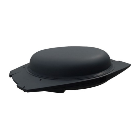
System Overview The SR1500 antenna system provides live satellite TV to a vehicle, while in motion. It is suitable for installation on any vehicle. It includes a receive panel and electronic circuits, and is designed, built, and ruggedized for outdoor operation. Figure 3: SR1500 antenna The SR1500 antenna is available in two versions: Uni Pol (one cable connection) antenna model supports a single TV screen –... -
Page 15: Power Requirements
Power Requirements The power consumption of the SR1500 antenna components is detailed below. Typical power consumption is relevant for general sizing of the power system to support the system. Maximum power consumption relates to extreme situations where the antenna ... -
Page 16: Antenna Components
Antenna Components The SR1500 antenna is a self-pointing mechanically steered Ku-band phase array antenna. The Uni Pol version provides reception (Rx) by a single antenna array panel at dual circular or linear polarizations. The Dual Pol version provides simultaneous V/H or RHCP/LHCP on 1.5GHz band on three simultaneous connections. In addition, the antenna can automatically search for, locate, and track a requested communication satellite. -
Page 17: Table 2: Antenna Components
Table 2: Antenna components Azimuth Motor Control unit for the azimuth motor. Control Azimuth Motor A belt-driven motion mechanism that turns the rotating platform in azimuth based on RSSI power levels and gyro block readings. Two-Axis Gyro The gyro block and inclinometer control part of the antenna acquisition and tracking process. -
Page 18: Figure 5: Sr1500 Dual Pol Connectors
Connectors Coaxial TNC bulkhead jack connectors, as follows: SR1500 Dual Pol - Three TNC connectors - Ctrl - 30V DC and Rx - Low band – Low band Rx - High band – High band Rx The Ctrl connector is configurable to H or V polarization and Low or High band. - Page 19 11 Static Dual BDC (Dual Pol version antenna only) Fully electronic proprietary device based on RaySat's MMIC technology, which assists the Pol configuration of additional set top boxes (STBs). After the first STB is configured as Vertical or Horizontal polarization setting with the ACU, the remaining STBs are automatically set with an opposite-pol configuration.
-
Page 20: System Description
System Description The SR1500 antenna system includes the following components. SR1500 Antenna, sometimes referred to as the Outdoor unit (ODU) (The antenna comes in Uni Pol or Dual Pol versions. The Dual Pol version is illustrated.) Figure 7: SR1500 antenna Antenna Control Unit (ACU) ... -
Page 21: Unpacking, Inspection, And Installation Planning
Unpacking, Inspection, and Installation Planning Prior to installing the system, inspect the supplied equipment to verify its content and integrity after shipping. The SR1500 system is supplied in one box containing the following components: SR1500 antenna Mounting kit and cable kit ... -
Page 22: Unpacking And Inspection
Unpacking and Inspection Open all the boxes before installing the components. Select a suitable location for opening the box - do not expose the contents to excessive humidity or extreme temperatures. Verify that all expected components are present: Verify that all components, cables, and accessories specified in the packing list are present. -
Page 23: Installing The Antenna On A Vehicle Roof
Installing the Antenna on a Vehicle Roof The following sections describes the types of antenna installation: Installation on a Vehicle Roof Rack, on page 19 Installation on a Bus, on page 21 Installation on a Double Decker Bus, on page 25 ... -
Page 24: Notes About Clamp Installation
Notes About Clamp Installation The SR1500 antenna clamps onto either roof rack crossbars or mounting legs with an adjustable, padded clamping system designed to secure the unit on the fixed base. The clamp brackets accommodate different size crossbars, and uneven crossbar widths. The clamp kit includes: an upper bracket assembly, which comes preinstalled on the antenna ... -
Page 25: Figure 14: Mounting Bracket Spacers
Ensure at least 2.5 cm distance between the antenna base and the roof surface. Failing to leave this distance may result in damage to the roof due to the bouncing of the antenna while the vehicle is in motion. Ensure that the brackets fit correctly on the crossbars or mounting legs. With crossbars that are arched, add spacers (not included) to the three brackets located opposite the azimuth motor, as needed. -
Page 26: Figure 16: Lower Bracket Placed Under The Crossbar
Insert the lower bracket with the rubber pad installed under the crossbar or leg, so that it is in-line with the upper bracket that is resting on the crossbar. Figure 16: Lower bracket placed under the crossbar Access the two head screws (No. 9) through the holes on the top of the antenna and thread them through both the upper and lower bracket assemblies. -
Page 27: Installation On A Vehicle Roof Rack
Installation on a Vehicle Roof Rack SUV and VIP vehicle installations are usually done on a roof rack. The antenna is clamped onto crossbars of the roof rack. Figure 19: Crossbar positioning on roof rack This procedure uses the adjustable, padded clamp kit described Notes About Clamp Installation, on page 16. -
Page 28: Figure 21: Equal Distance To The Center Of The Roof
Measure the distance between the antenna’s mounting bracket to the roof’s edge to make sure the antenna is centered on the roof. Complete this for the front and rear crossbars. Figure 21: Equal distance to the center of the roof Verify that sun/moon roof or other vent system will work properly without interfering with the antenna or mounting brackets. -
Page 29: Installation On A Bus
Installation on a Bus This procedure describes how to install the SR1500 antenna on a bus. The Gilat metal leg kit is recommended for mounting the antenna on a bus roof. See Bus Mount Kit, on page 42. Figure 22: Metal legs installed on bus roof The antenna is mounted on the legs using adjustable, padded clamps. -
Page 30: Figure 23: Antenna Bus Installation Dimensions
Define the position of the four metal legs on the roof. o Mark the center points of the metal legs on the roof. For the leg positions, see the bus installation dimensions drawing below. The metal legs are not located symmetrically. It is important to observe the dimensions precisely. -
Page 31: Figure 24: Sanded Rectangles On The Bus Roof
Mount the metal legs on the roof. Place the legs on the roof, orientated as shown in the drawing. Precisely adjust the position of each leg. You must see the cross mark you made on the roof through the central hole of the base plate of the leg. Press the leg firmly to the roof and drill 8 (eight) holes with diameter Ø2.8 mm through the 8 holes Ø5 of the base plate. -
Page 32: Figure 25: Preparing The Antenna For Mounting
Mount the antenna on the metal legs installed on the roof. Remove the rubber plugs from the access holes on the top of the antenna. If the lower brackets of the brackets are already installed, uninstall them by unscrewing the head screws through the access holes. Figure 25: Preparing the antenna for mounting With the upper brackets still installed, place the antenna on top of the already mounted metal legs. -
Page 33: Installation On A Double Decker Bus
Installation on a Double Decker Bus This section provides general guidelines for SR1500 antenna placement in a 45 foot double decker bus, or other situations where mounting on top of a roof is not practical. In this case the antenna can be mounted either indoors (inside the roof at the back of the bus), or outdoors on a trailer. -
Page 34: Outdoor Trailer Installation
The antenna is clamped to the chassis crossbars or legs using the standard installation kit clamps. The clamping procedure is similar to that described in Before You Start, on page 15. Figure 29: Antenna is clamped to crossbars or legs Outdoor Trailer Installation The antenna can be mounted on a trailer, behind the bus. -
Page 35: Installation On A Train
Installation on a Train The recommended mounting procedure involves the following aspects: Four metal damper legs installed on the train rooftop rails. The damper legs are designed to absorb impact in three dimensions. Crossbars mounted on the dampers The antenna attached to the crossbars ... -
Page 36: Figure 33: Crossbars Mounted On Damper Legs On Train Rooftop Rails
Attach the damper legs to the train rooftop rails through four drill holes on each leg. Figure 33: Crossbars mounted on damper legs on train rooftop rails Attach the crossbars to the damper legs with screws from the assembly kit. Attach the antenna to the crossbars with screws from the assembly kit. -
Page 37: Installing The Indoor Equipment And Routing The Cables
Installing the Indoor Equipment and Routing the Cables This section provides general guidelines on how to install the ACU and satellite receiver inside the vehicle. Placing the ACU and Receiver Plan the location of the ACU and satellite receiver in a dry and protected area, away from any heat source and in an area with proper ventilation. -
Page 38: Routing Cables Into The Vehicle
Routing Cables Into the Vehicle This section describes how to route the coaxial RF antenna cables inside the vehicle. The SR1500 Dual Pol version involves three cables from the antenna, the Uni Pol version involves one cable. You can route the antenna cables into the vehicle through an existing point of entry. On an SUV this can be behind the hatch, between two body panels, or through a grommet. -
Page 39: Routing Cables Through The Rear Hatch Of An Suv
Routing Cables Through the Rear Hatch of an SUV You can route the cable into the vehicle behind the rear hatch. To route the cables through the rear hatch: Run the cable along the roof rack to the back of the vehicle. With the hatch open, route the cable behind the hatch to inside the vehicle. -
Page 40: Routing Cables Through A Grommet
Routing Cables Through a Grommet Many vehicles have grommets located in different areas of the under carriage. Many grommets are large enough to fit multiple coaxial cables, even with the connectors still attached. Be sure to seal the grommet with a silicone sealant once the cables are installed to the equipment rack. -
Page 41: Connecting The System
Connecting the System This section describes how to connect the system components and how to connect the system to power. Connecting the Cables to the Antenna This section describes how to connect the coaxial RF cables to the antenna, and how to route the cables inside the vehicle to the ACU location. -
Page 42: Connecting The System Components
Connecting the System Components These figures show the cable connections between the SR1500 system components. See also Polarization Configuration, on page 36, and Appendix D – Basic Cable Kit Contents, on page 44. SR1500 Dual Pol Connectivity Figure 40: SR1500 Dual Pol Connectivity Table 4: Wiring connections for SR1500 Dual Pol Connectivity From Connector... -
Page 43: Sr1500 Uni Pol Connectivity
SR1500 Uni Pol Connectivity Figure 41: SR1500 Uni Pol Connectivity Table 5: Wiring connections for SR1500 Uni Pol Connectivity From Connector Connector Cable P/N Purpose TNC L-band TNC L-band CBM1000010 Ant. Ctrl Rx ODU Out Rx ACU Out L-band Rx DC &... -
Page 44: Polarization Configuration
Polarization Configuration Uni Pol Antenna The Uni Pol version antenna includes one Ctrl TNC connector, which connects to the ACU. The STB is connected through the ACU. Using the ACU, the STB is configured to operate with either Horizontal or Vertical polarization in either Low Band or High Band. -
Page 45: Connecting The System To Power
Connecting the System to Power Once all the system cables are connected, you can connect the system to the vehicle power. These procedures should be viewed as basic guidelines. They do not cover all levels of integration into existing entertainment systems. Your application may require a different approach depending on existing vehicle accessories. -
Page 46: Figure 42: Acu To Battery Lead Installed With 15Amp Fuse
Install the in-line fuse: Locate the in-line fuse holder (included in the kit). Lift the protective cap off and remove the 15 amp fuse. Cut the fuse holder wire loop in half so that you have two equal length ends. Attach one end of the fuse holder as close as possible (within 45cm) to the switched accessory wire that you located in Step 2), preferably by soldering and taping. -
Page 47: Alternative Power Connection - Directly To Battery
Alternative Power Connection – Directly to Battery You can also connect the system directly to the vehicle 12 V battery. Figure 43: Power supplied from the battery running through the Ignition Take special care when connecting the system directly to the vehicle’s battery. It is recommended that an external, single pole double throw (SPDT) relay be installed. -
Page 48: Appendix A - Gilat Approved Roof Bars
Appendix A – Gilat Approved Roof Bars This document assumes that the antenna is mounted on a roof rack with crossbars that meets Gilat’s standards for weight and stress tolerances for antenna rooftop mounting. The following roof racks are approved for antenna mounting on vehicles. Thule ... -
Page 49: Appendix B - Antenna Mounting Hardware
Appendix B – Antenna Mounting Hardware The antenna comes with hardware kits to assist mounting the antenna on the vehicle roof. Clamp Kit The clamp kit is supplied with the antenna and is applicable for most vehicle applications. The antenna comes with upper clamp supports preinstalled at each of the four antenna mounting positions on the antenna. -
Page 50: Bus Mount Kit
Bus Mount Kit The following kit is used to install the antenna on a bus. Table 9: AKT2000066 Bus mount kit MMP2000033 Bus Mount Metal Leg MFS0000341 Screw 4.0X20 Pan Head Self Tapping PT BN MFS2000163 Screw 4.2X19 Tapping PH DIN7981 A2 Figure 47: Antenna mounted on leg | Gilat Satellite Networks | Confidential and Proprietary Information... -
Page 51: Appendix C - Antenna Dimensions
Appendix C - Antenna Dimensions The following diagrams show the dimensions of the SR1500 antenna (Dual Pol and Uni Pol). Note the distance between spacers for marking the location of legs on a vehicle roof. Figure 48: SR1500 dimensions – side view Figure 49: SR1500 dimensions –... -
Page 52: Appendix D - Basic Cable Kit Contents
Appendix D – Basic Cable Kit Contents The composition of the cable kit supplied with the antenna depends on whether the Uni Pol or Dual Pol version of the antenna is ordered, and the length of cables required. The specific cables supplied depend on details in the sales order. Table 10: Cable Kit for SR1500 antenna Conn# column refers to the connection number in the Connectivity table. -
Page 53: Appendix E - Configuring And Operating The Antenna With Acu
Appendix E – Configuring and Operating the Antenna with ACU An ACU is needed to configure and operate the antenna. You can use either the ACU web interface or LCD configuration options to configure the ACU to operate and control the antenna and to verify proper operations. Entering the configuration mode and changing parameters should only be done by a qualified technician after reading this document. -
Page 54: Acu Controls
ACU Controls This section describes the ACU unit front and rear panel controls. Front View Figure 51: ACU front panel controls Table 11: ACU front panel controls Button Description On/Standby Allows the ACU to be placed in standby mode, without needing to turn the unit off with the power switch located on the back. -
Page 55: Rear View - Acu Cable Connections
Rear View – ACU Cable Connections Verify that all connections are correct and finger tight before powering on. Turn on the power using the switch located on the back of the ACU. Only use the inverter on the back of the ACU for providing power for the satellite modem. -
Page 56: Operating The Acu
Operating the ACU This section describes the system and power connections to the ACU, and how to begin operation after the system is configured. Connecting the ACU to the System Connect the ACU unit to the system as described in Connecting the System, on page 33. -
Page 57: Configuring The Antenna With The Acu Web Interface
An improper command can cause the antenna to malfunction. See Maintenance, on page 67. RAYSAT Takes you to Gilat RaySat’s website. You must have an Internet connection for this capability. Logout Logs the user out from the ACU Configuration. See Logging Out, on page 69. -
Page 58: Accessing The Acu Web Interface
Accessing the ACU Web Interface The following procedure describes how to access pages in the Web interface. Buttons in the Interface Pages Read-only pages include a Refresh button that updates the parameters displayed to current values. Pages that allow editing values include the following buttons: ... -
Page 59: Figure 53: Acu Web Interface - Idu Configuration Page
Figure 54: ACU web interface – Login Enter the login credentials: o In the Login field, type admin. o In the Password field, type raysat. o Click Submit. The IDU Configuration page is now displayed in the Authenticated User mode. -
Page 60: Monitoring Acu Parameters
Monitoring ACU Parameters You can display ACU parameters for monitoring purposes, including ACU status details. To monitor ACU parameter settings: In the IDU Configuration page, click IDU. This page enables you to monitor ACU parameters. Figure 55: ACU web interface – Monitor IDU Parameters Table 14: ACU web interface –... -
Page 61: Table 15: Acu Status Messages And Their Interpretation
Table 15: ACU Status messages and their interpretation Parameter Description Idle The ACU and antenna are in passive state (displayed during starting-up process). Initialization The antenna performs initial adjustments. Acquisition Initial search for satellite. Checking Antenna stopped on a signal, the satellite is being verified. Tracking The correct satellite is found, the antenna is tracking the signal. -
Page 62: Monitoring Antenna Parameters
Parameter Description Overheating! Antenna temperature is too high. Gyro failure! Failure in antenna gyroscopes. Accel. failure! Failure in antenna accelerometers. Monitoring Antenna Parameters You can display antenna parameters for monitoring purposes. To monitor ACU parameter settings: In the IDU Configuration page, click Antenna. This page enables you to monitor antenna parameters. -
Page 63: Configuring Acu And Antenna Parameters
Parameter Comments Longitude Longitude coordinate of antenna GPS. Elevation Current antenna elevation. Azimuth Current antenna azimuth (available on some antenna models). Rx Polarization Rx polarization angle. Configuring ACU and Antenna Parameters You can edit ACU or antenna parameter settings. To edit ACU or antenna parameter settings: In the IDU Configuration page, click Configuration. -
Page 64: Figure 58: Antenna Configuration Page
Parameter Value Range Description Temp. Units Celsius/Fahrenheit Temperature units IDU Baud Rate 1200 - 460800 Specifies the baud rate on S.Port 2 (PC interface). The value is stored permanently and is not reset at power-up. LED Mode Normal/Stealth Enables (Normal) or Disables (Stealth) the ACU LEDs Antenna Configuration This page configures the available band details of the currently installed LNB, and... -
Page 65: Configuring Satellite Settings
Parameter Value Range Description LNB Voltage 13V/18V BDC power voltage. 22kHz Tone Off/On/Auto BDC control tone. LNB (Low Noise Block) in the interface should be understood to mean BDC (Block Down Converter). Configuring Satellite Settings You can manage the internal satellite database. To access and work with Satellite pages: In the IDU Configuration page, click the Satellite menu option. -
Page 66: Figure 60: Create Satellite
Creating a Satellite The Create Satellite page allows you to define a new satellite in the satellite database. After the satellite is created, the parameters can be edited in the Satellite parameters page. See Editing a Satellite, below. To define a new satellite: Access the Satellite Settings page –... - Page 67 Parameter Value Range Description Freq (MHz) 0 or a value from 10950 to 12750 Tracking frequency is typically entered in the Web-interface. On some satellite modem models, if left as 0, the ACU will try to obtain the frequency from the modem. Modems that support this feature include: Agilis, Datum, Comtech, Gilat_SE2, Vipersat_HW,...
-
Page 68: Figure 61: Satellite Parameters Edit
Editing a Satellite The Edit Satellite page allows editing values for an existing satellite in the satellite database. The Edit Satellite page appears the same as the Create Satellite page – See Creating a Satellite. All parameters except Name and Position are editable. To edit satellite values: Access the Satellite Settings page –... -
Page 69: Configuring Network Settings
Configuring Network Settings The Network link leads to pages for network administration use. Static Network Settings Dynamic Network Settings Advanced Network Settings Static, Dynamic, and Advanced Settings pages are accessed via links on every page. Other pages are accessed as specified. To access and work with Network settings: In the IDU Configuration page, click the Network menu option. -
Page 70: Figure 63: Dynamic Network Settings
Dynamic Network Settings This page manages the embedded DHCP Client/Server. When Client is selected, the Show Dynamic Parameters link is available. When Server is selected, the Show Clients link is available. Dynamic settings must be used if a router is connected to the system. Then, when the DHCP is in Client mode, the router will distribute the IP addresses dynamically. -
Page 71: Figure 64: Static Network Parameters
Dynamic Network Parameters This page shows network parameters obtained by a DHCP server when the IDU is working in DHCP Client mode. This page can be accessed from the Dynamic Network Settings page when the selected DHCP mode is Client. Figure 64: Static Network Parameters Table 22: ACU web interface - Dynamic Network Parameters Parameter... -
Page 72: Figure 65: Dhcp Clients
DHCP Clients This page shows the active DHCP clients served by the IDU when it is working in DHCP Server mode. This page can be accessed from the Dynamic Network Settings page when the selected DHCP mode is Server. Figure 65: DHCP Clients Table 23: ACU web interface - DHCP Clients Parameter Description... -
Page 73: Figure 66: Advanced Network Settings
Advanced Network Settings This page mainly concerns aspects of integrated services. It enables changing default port values as well as setting service timeouts, enabling/disabling the Telnet remote echo, and setting the working mode of the Ethernet controller. Figure 66: Advanced Network Settings Table 24: ACU web interface - Advanced Network Settings Parameter Value Range... -
Page 74: Antenna Log
Antenna Log This page logs antenna messages (typically several kinds of alarms): Figure 67: Antenna Log To erase the logs, click Erase. To update the displayed information, click Refresh. Table 25: ACU web interface – Antenna Log parameters Parameter Comments Ant. -
Page 75: Maintenance
Maintenance The Maintenance link enables you to perform the following types of manual maintenance operations. Point the antenna to a satellite position and send a command to the antenna. Set antenna LNB parameters and tune the integrated DVB tuner in the ACU. ... -
Page 76: Table 26: Acu Web Interface - Maintenance Parameters - Pointing
Pointing the antenna and sending a command You can point the antenna to the specific satellite position and send a randomly chosen valid command directly to the antenna. To point the antenna to a specific satellite position: Pointing parameters - Used to point the antenna to a specific satellite position, and to send a valid command directly to the antenna. -
Page 77: Logging Out
Monitoring You can monitor antenna BER, NID, RSSI values, and the modem E value. Table 28: ACU web interface - Maintenance parameters – Monitoring Parameter Value Range Description BER (bit error rate) of the received signal Identification data, Network ID. RSSI 10000 –... -
Page 78: Antenna Status Bits
Antenna Status Bits Antenna statuses are expressed in some system messages as Hexadecimal bit masks. This table lists the corresponding explanations. Table 29: Antenna Status Bits Bit Mask Bit Explanation 0x00000001 General failure 0x00000002 Motor current limit reached 0x00000004 Temperature limit reached 0x00000008 Low voltage condition detected 0x00000020... -
Page 79: Configuring The Acu With The Acu Lcd Display
Configuring the ACU with the ACU LCD Display The ACU menus are used to program antenna parameters. To view the ACU menu options: Press the Enter button to bring up the following menus: o Diagnostics LCD Parameters, see page 72. o Setup LCD Parameters, see page 73. -
Page 80: Diagnostics Lcd Parameters
Diagnostics LCD Parameters Table 30: ACU LCD - Diagnostics parameters LCD Indication Description Software Version - Displays software versions of both the ACU and antenna, also known as the Outdoor Unit (ODU). Satellite Database - Displays the current database. Satellite Recognition - Displays the current satellite recognition version. -
Page 81: Setup Lcd Parameters
LCD Indication Description RSSI Frequency - Displays the antenna RSSI frequency. RSSI - Displays the antenna RSSI level. RSSI BW - Displays the antenna RSSI filter bandwidth. RSSI Threshold - Displays the antenna RSSI threshold. Setup LCD Parameters Table 31: ACU LCD - Setup parameters LCD Indication Description Receiver - Select the type of satellite TV receiver being... -
Page 82: Install Lcd Parameters
Install LCD Parameters Table 32: ACU LCD - Install parameters TV Satellites - Used to select the correct TV satellite. Not used for two-way data communications. Check Switch - Used to run a switch test for some TV satellite receivers. Not used for data communications. Polarization - Used to select the appropriate polarization of the satellite signal (H, L, or Auto). -
Page 83: Table 34: Acu Lcd - Ip Config Dynamic Network Parameters
LCD Indication Description Hub IP - Used to enter the hub (remote) terminal IP address so the IP-based modem can gather ping replies from the hub and properly reply the Lock status to the ACU. (For satellite modems that communicate with the ACU by RS232, this setting is not used.) MAC Address - Used to enter the ACU’s MAC address - physical (hardware, Media Access Control) address. -
Page 84: Table 35: Acu Lcd - Ip Config Advanced Network Parameters
LCD Indication Description Dynamic Gateway - Gateway address, obtained by the server. DHCP Server – DHCP server that allocates the parameters. Lease Time Left - Remaining parameter allocation time. When the ACU is in DHCP server mode, information about active DHCP clients served by the ACU are shown: MAC Address - MAC (physical) address of the given client. -
Page 85: Manual Mode Lcd Parameters
Manual Mode LCD Parameters Table 36: ACU LCD – Manual Mode parameters LCD Indication Description RSSI Freq. - Used to set the RSSI frequency in MHz. Band - Used to set the High or Low band of operation. Polarization - Used to set the Vertical (or RHCP) or Horizontal (or LHCP) polarization of operation. -
Page 86: Appendix F - Troubleshooting
Appendix F – Troubleshooting Check this list for the problem and specific fixes. Table 39: Problems and fixes Problem Fixes System does not power on. Verify that the ACU and receiver are powered on. Check for blown fuses. Verify all cables are connected properly. Verify vehicle battery has been reconnected properly. - Page 87 Problem Fixes Intermittent picture for Ensure that all video connections are installed short intervals. properly. Confirm clear line of sight to the satellite. Verify that the receiver is tracking on the satellite from the Setup Menu of the receiver. Check that the radome of the antenna is free of any obstructions (water, snow, ice, or debris).
-
Page 88: Appendix G - Specifications
Appendix G – Specifications The specifications for the SR1500 are listed in the following table. Table 40: Technical specifications for SR1500 Parameter Description Mechanical Antenna size 115 L x 90 W x 24 H cm (45 x 35 x 9.45 in) Antenna weight 32 kg (70.5 lb) ACU size... - Page 89 Parameter Description Satellite Service Frequency Ku-band Supports satellites with EIRP ≥50 dBW Supports regional DTH/FTA Examples: services OSN, FTA channels on NileSat, BADR, Arabsat and many Middle East more All FTA channels on Astra & HotBird, Freesat, BSkyB, Europe SKY IT, Canal+, NTV+, Digiturk, many others Latin America Dish-MX, Sky-BR, Claro, DTVLA and more Dish-TV, Airtel, Tata Sky DD, TrueVisions, Foxtel and...
-
Page 90: Appendix H - Acronyms And Abbreviations
Appendix H – Acronyms and Abbreviations Antenna Control Unit Block Down Converter Bit Error Rate Fixed Satellite Service Block Up-Converter Customer Furnished Equipment COTM Communication On-The-Move Central Processing Unit CTRL Control Continuous Wave Direct Current Federal Communication Commission Fixed Satellite Service For Use With Gigahertz GRND... - Page 91 Power Distribution Unit PSTN Public Switched Telephone Network RHCP Right-hand Circular Polarization Return Material Authorization RSSI Receive Signal Strength Indicator Receive SCPC Single channel per carrier Signal-Noise Ratio SOTM Satellite Communication On-The-Move Threaded Neill-Concelman Transmit Volts Alternating Current Volts Direct Current Wide Area Network WLAN Wide Local Area Network...
- Page 92 | Gilat Satellite Networks | Confidential and Proprietary Information...
Need help?
Do you have a question about the Gilat SR1500 and is the answer not in the manual?
Questions and answers