Table of Contents
Advertisement
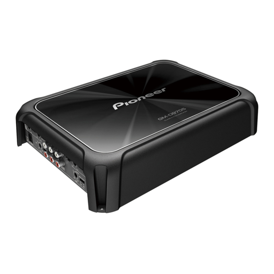
CLASS D FIVE-CHANNEL AMPLIFIER
GM-D9705
GM-DX975
PIONEER CORPORATION
PIONEER ELECTRONICS (USA) INC. P.O. Box 1760, Long Beach, CA 90801-1760, U.S.A.
PIONEER EUROPE NV Haven 1087, Keetberglaan 1, 9120 Melsele, Belgium
PIONEER ELECTRONICS ASIACENTRE PTE. LTD. 2 Jalan Kilang Barat, #07-01, Singapore 159346
PIONEER CORPORATION 2019
28-8, Honkomagome 2-chome, Bunkyo-ku, Tokyo 113-0021, Japan
GM-D9705/XEVEL
/XEVEL
ORDER NO.
CRT6391
/XEVEL
K-ZZZ JAN. 2019
Advertisement
Table of Contents

Related Manuals for Pioneer GM-D9705/XEVEL


Summary of Contents for Pioneer GM-D9705/XEVEL
- Page 1 PIONEER CORPORATION 28-8, Honkomagome 2-chome, Bunkyo-ku, Tokyo 113-0021, Japan PIONEER ELECTRONICS (USA) INC. P.O. Box 1760, Long Beach, CA 90801-1760, U.S.A. PIONEER EUROPE NV Haven 1087, Keetberglaan 1, 9120 Melsele, Belgium PIONEER ELECTRONICS ASIACENTRE PTE. LTD. 2 Jalan Kilang Barat, #07-01, Singapore 159346 PIONEER CORPORATION 2019 K-ZZZ JAN.
-
Page 2: Table Of Contents
9.1 PACKING SECTION ..............................10 9.2 EXTERIOR SECTION..............................12 10. SCHEMATIC DIAGRAM ..............................14 10.1 P.C.B TOTAL ASSY(MAIN)............................14 10.2 P.C.B TOTAL ASSY(SW-IN) ............................15 11. PCB CONNECTION DIAGRAM ............................16 11.1 P.C.B TOTAL ASSY(MAIN)............................16 11.2 P.C.B TOTAL ASSY(SW-IN) ............................18 12. ELECTRICAL PARTS LIST ...............................19 GM-D9705/XEVEL... -
Page 3: Service Precautions
When the parts that are fixed by BRACKET (IC40, IC41, IC44, D42, D43, D44, D45, Q20, Q21, Q22, Q23, Q24, Q25, Q515, Q516, Q517 and Q518) replace, follow the below procedure. Caution : While the picture shown is slightly different from this model in shape, the replacing procedure is the same. GM-D9705/XEVEL... -
Page 4: Others
For environmental protection, lead-free solder is used on the printed circuit boards mounted in this unit. Be sure to use lead-free solder and a soldering iron that can meet specifications for use with lead-free solders for repairs accompanied by reworking of soldering. GM-D9705/XEVEL... -
Page 5: Specifications
Sound interrupted 3.2 JIGS LIST - Lubricants and Glues List Name Grease No. Remarks Grease GEM1057 Applying to BRACKET Bond GYL1006 Applying to P.C.B TOTAL ASSY(MAIN) 4. BLOCK DIAGRAM There is not information to be shown in this chapter. GM-D9705/XEVEL... -
Page 6: Diagnosis
5. DIAGNOSIS 5.1 CONNECTOR FUNCTION DESCRIPTION Front Rear 6. SERVICE MODE There is not information to be shown in this chapter. GM-D9705/XEVEL... -
Page 7: Disassembly
Remove 6 pcs screw and then remove the Chassis. Chassis Fig. 1 - Removing the P.C.B TOTAL ASSY(SW-IN) (Fig. 2 and Fig. 3) P.C.B TOTAL ASSY(SW-IN) Remove 4 pcs screw. Pull and remove the P.C.B TOTAL ASSY(SW-IN). Fig. 2 Fig. 3 GM-D9705/XEVEL... - Page 8 Remove 8 pcs screw and then remove the P.C.B TOTAL ASSY(MAIN). P.C.B TOTAL ASSY(MAIN) Fig. 5 _ Caution of Re-installation of the P.C.B TOTAL ASSY(MAIN) When the heatsink will be set, take care not to pinch the wire of Thermistor. GM-D9705/XEVEL...
-
Page 9: Each Setting And Adjustment
Bonding Position : GYL1006 8. EACH SETTING AND ADJUSTMENT There is not information to be shown in this chapter. GM-D9705/XEVEL... -
Page 10: Exploded Views And Parts List
Screw adjacent to mark on the product are used for disassembly. For the applying amount of lubricants or glue, follow the instructions in this manual. (In the case of no amount instructions,apply as you think it appropriate.) 9.1 PACKING SECTION GM-D9705/XEVEL... - Page 11 L308121040010S Screw,Tapping (3 mm x 10 mm) B010430103B10V Bass Boost Remote Control 7025CX1801100 Screw,Tapping (4 mm x 18 mm) B010440183B10V (2) CONTRAST TABLE GM-D9705/XEVEL and GM-DX975/XEVEL are constructed the same except for the following: Mark Description GM-D9705/XEVEL GM-DX975/XEVEL Box,Gift 6007213670060V...
-
Page 12: Exterior Section
9.2 EXTERIOR SECTION GM-D9705/XEVEL... - Page 13 Screw,Tap Tite B020030081B10SV Bracket 4010216766000V Bracket 4010216766100V Screw 1507041146010SV Supporter 4070212667000V (2) CONTRAST TABLE GM-D9705/XEVEL and GM-DX975/XEVEL are constructed the same except for the following: Mark Description GM-D9705/XEVEL GM-DX975/XEVEL Heat Sink Assy 7025CX1801119 7025CX180111A P.C.B Total Assy(MAIN) 7025CX1810010 7025CX1811010 P.C.B Total Assy(SW-IN)
-
Page 14: Schematic Diagram
10. SCHEMATIC DIAGRAM P.C.B TOTAL ASSY(MAIN) Note: When ordering service parts, be sure to refer to " EXPLODED VIEWS AND PARTS LIST" or "ELECTRICAL PARTS LIST". R521 10K-D 22/50V CHASSIS GND R320 C215 68N-M/100V FB106 JK1-C 33/50V 22/50V C514 C189 RCA INPUT A A-CH 68N-M/100V... -
Page 15: Total Assy(Sw-In)
P.C.B TOTAL ASSY(SW-IN) R232 IC15 C510 NJM4580CG IC16 VR5-A AB-CH/S-CH NJM4580CG C50K*4 S-SLOPE 100N-M/100V GAIN C203 B10K*2 R264 2N2/50V VR5-B 24dB C50K*4 R270 S-LF R258 12dB FREQ VR5-C CSS-2219 C50K*4 A/B-SW CSS-2219 C512 SLOPE INPUT R269 68N-M/100V VR5-D LED-B LED-B C50K*4 LED-A LED-A... -
Page 16: Pcb Connection Diagram
11.PCB CONNECTION DIAGRAM NOTE FOR PCB DIAGRAMS Capacitor Connector P.C.B TOTAL ASSY(MAIN) SIDE A 1.The parts mounted on this PCB include all necessary parts for SIDE A several destination. For further information for respective destinations, be sure to check with the schematic dia- SIDE B gram. - Page 17 P.C.B TOTAL ASSY(MAIN) SIDE B...
-
Page 18: Total Assy(Sw-In)
11.2 P.C.B TOTAL ASSY(SW-IN) SIDE A P.C.B TOTAL ASSY(SW-IN) FREQ SLOPE GAIN A/B-SW POWER/PROTECT BASS BOOST INPUT INDICATOR REMOTE CN51 BASS BOOST REMOTE CONTROL VR3-B SIDE B P.C.B TOTAL ASSY(SW-IN) GM-D9705/XEVEL... -
Page 19: Electrical Parts List
The expression of the unit in this manual is shown by u instead of . Please do not make a mistake. Circuit Symbol and No. Part No. Circuit Symbol and No. Part No. IC 502 IC,LINEAR OP J121458000050S A:GM-D9705/XEVEL B:GM-DX975/XEVEL IC 516 IC,ANALOG J080209301010S SEMI,CHIP TR/NPN 2SC J522555100010S Unit Number : 7025CX1810010 (A) - Page 20 K005041480230S D 21 D,SWITCHING CHIP K005041480230S L 503 COIL,TOROIDAL(RING) 10 uH D305010350010S D 22 D,SWITCHING CHIP K005041480230S POWER TRANS 8200491900020V D 23 D,SWITCHING CHIP K005041480230S POSISTOR F320184710051S D 24 D,SCHOTTKY K120020200050S POSISTOR F320471000950S THERMISTOR F340550200020S D 25 D,SCHOTTKY K120020200040S GM-D9705/XEVEL...
- Page 21 R 224 N113138647210S C 153 D02410206C060S R 586 N113138610020S C 157 D041470085230S R 587 N113138610020S C 158 D041220087230S R 655 N113138647030S C 180 D041220087230S R 656 N113138647030S C 186 D041470084230S R 657 N113138647030S C 215 D041330087230S R 658 N113138647030S GM-D9705/XEVEL...
- Page 22 C 173 D041220087230S C 174 D041010087230S C 175 D02418406C060S C 200 D041470084230S C 201 D041220087230S C 510 D02410406C060S C 511 D02456306C060S C 512 D02468306C060S C 513 D02427306C060S C 515 D02418406C060S C 518 D041101083240S C 521 D041100087230S C 525 D0412R2087230S GM-D9705/XEVEL...
Need help?
Do you have a question about the GM-D9705/XEVEL and is the answer not in the manual?
Questions and answers