Table of Contents
Advertisement
Advertisement
Table of Contents

Related Manuals for Mototok SPACER 8600 MA

Summary of Contents for Mototok SPACER 8600 MA
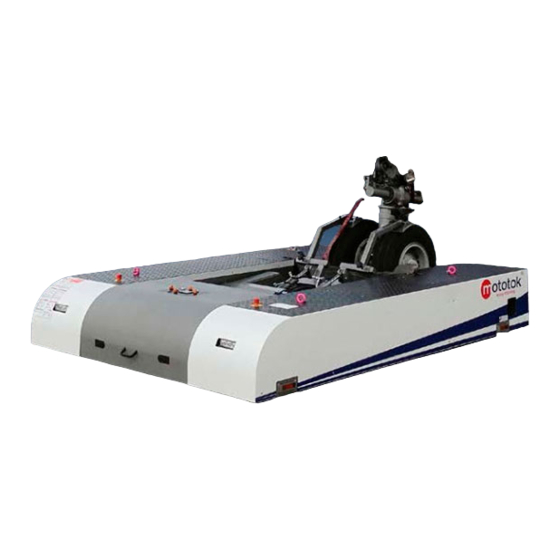
- Page 1 OperationManual SPACER8600MA TheNewStandardof Manoeuvrability.
-
Page 2: Table Of Contents
6. BATTERIES . . . . . . . . . . . . . . . . . . . . . . . . 32 6.1. Batteries for the radio remote control 6.2. Batteries for the mototok 7. TECHNICALDATA . . . . . . . . . . . . . . . . . . . . . .43 7.1. - Page 3 10.MAINTENANCE&TROUBLESHOOTING . . . . . . . . . . . . . .65 10.1. Annual maintenance check list 10.2. Lifetime of parts 10.3. Testing the oversteering protection 10.4. Hydraulic Oil Responsibleforallcontent Mototok International GmbH Mr. Kersten Eckert Hohenzollernstr. 47 D-47799 Krefeld Germany Phone: +49 2151 6508382...
-
Page 4: Safetyadvice
1.SAFETYADVICE 1. SAFETYADVICE 1.1. Instructionsforoperators 1.2. Safetybriefing 1.3. Genericalarmoutput 1.4. Adjustingthecontactpressureoftheslidingtable 1.5. Safetyadvicewhenliftingthenosegear... -
Page 5: Instructions For Operators
Attention! ❐ Please read the MOTOTOK Instruction Manual thoroughly and carefully. ❐ Do not use the MOTOTOK before checking that it is in perfect technical condition and for any external damage 1.1. INSTRUCTIONSFOROPERATORS Operation of the MOTOTOK is allowed only by qualified persons who are physically and mentally capable to do so. - Page 6 1.SAFETYADVICE/INSTRUCTIONSFOROPERATORS Attention! ❐ Don’t put hands or any other body parts underneath the lifting gear or under the MOTOTOK. Take care also that no objects are left lying around in this area. ❐ While crossing hangar door guide rails, the ground clearance must be at least around 8,8 cm.
- Page 7 ❐ All measures representing an infringement of this regulation may lead to the loss of your operating license and the guarantee. ❐ Use the EMERGENCY STOP system only if mototok drives arbitrarily. If the emergency stop button is used, the electric system shuts off completely. That means, that the generator brakes and the steering are functionless.
-
Page 8: Safety Briefing
Is the tail of the plane free to move? When the MOTOTOK lifts the front nosegear of the aircraft, the tail is slightly lowered. This can cause the stabilizer or the side rudder to bump against a wall or another aircraft if suffi cient clearance is not taken in accordance before lifting. - Page 9 1. S AFETYADVICE/SAFETYBRIEFING Warning!Danger! ❐ It is not permitted to stand in the path of the Mototok’s pivot area during movements.
-
Page 10: Generic Alarm Output
1.SAFETYADVICE/GENERICALARMOUTPUT 1.3. GENERICALARMOUTPUT The generic alarm output uses a sequency of long and short pulsed alarm interleaved with short and long pauses. The following signals are used in the priority as shown in the table Priority Signal Graphic Representation Reaching the maximum permissible .... -
Page 11: Adjusting The Contact Pressure Of The Sliding Table
1. S AFETYADVICE/ADJUSTINGTHECONTACTPRESSUREOFTHESLIDINGTABLE 1.4. A DJUSTINGTHECONTACTPRESSUREOFTHE SLIDINGTABLE 1.lockingring 2.maximum pressure 3.minimum pressure For aircraft with small nose wheels or tires with low pressure it may be necessary to reduce the maximum contact pressure of the sliding table. 1. Rotate the upper black locking ring to unlock the lower orange setting rings. 2. -
Page 12: Safety Advise When Lifting The Nose Gear
1. S AFETYADVICE/SAFETYADVISEWHENLIFTINGTHENOSEGEAR 1.5. S AFETYADVISEWHENLIFTINGTHENOSEGEAR Please note, that if lifting the nose gear upwards, the tail of the aircraft will move down. The lowering of the tail may multiple times bigger than the lifting of the nose gear due to the geometry of the aircraft. -
Page 13: Generalinformation
2.GENERALINFORMATION 2. GENERALINFORMATION 2.1. Service 2.2. Transport 2.3. Maintenance 2.4. Warranty 2.5. Stability 2.6. Inspectionfordefects 2.7. Recycling 2.8. Emergencystopsystem/Emergencyswitch... -
Page 14: Service
2.GENERALINFORMATION/SERVICE 2.1. S ERVICE In case of a defect, you must contact a MOTOTOK Service Technician. If your contact person is not available, please contact directly: MOTOTOK International GmbH Tel. +49-2151-6 50 83 82 e-Mail: info@mototok.com or mobile: Mr. Kersten Eckert +49-172-7390400 2.2.... -
Page 15: Maintenance
❐ Before operation or maintenance of the MOTOTOK, make yourself thoroughly familiar with this handbook. ❐ The owner and/or the distributor of the MOTOTOK is/are responsible for ensuring that devices for the wireless transmission of control commands are checked by a technical expert regularly, but at a minimum once a year. -
Page 16: Stability
Any damage detect- ed must be reported immediately. Before continuing to operate the MOTOTOK, the owner has to repair any damage that may affect security. Safety defects are for example: ❐... -
Page 17: Emergency Stop System / Emergency Switch
The switches are red plastic covers which can be activated by hitting them and are located on the MOTOTOK at each corner. Each switch interrupts the supply of current to the vehicle. On the remote control there is an emergency stop switch with a red plastic cover in the middle of the panel. -
Page 18: Operationsi
3.OPERATIONSI 3. OPERATIONSI 3.1. Display&dashboard 3.2. Remotecontrol 3.3. Panel 3.4. Display... -
Page 19: Display And Dashboard
3.OPERATIONSI/DISPLAYANDDASHBOARD 3.1. DISPLAYANDDASHBOARD 1. The main switch turns on the remote control and the DC/AC converter. Only then can the radio remote control switch on the vehicle be activated. 2. Red signal lamp, indicates the process of automatic engaging or disengaging of the nosewheel. -
Page 20: Remote Control
If there is no RE- from the remote control to the control board. SET (green button) the Mototok does not react to the joystick or any other F. Green LED – shows the established connection between transmitter and button command. -
Page 21: Panel
3.OPERATIONSI/PANEL 3.3. P ANEL A. Emergency Stop B. Eyebolts for transporting C. Driving Direction Indicator Lights D. Display E. Driving Lights F. Security Paddles G. Cover for the charger socket... -
Page 22: Display
3.OPERATIONSI/DISPLAY 3.4. DISPLAY A. Display B. Battery Voltage C. Display of the Left Drive / Left Drive Error Code D. Display of the Right Drive / Right Drive Error Code E. The Error Code of the Control Board F. Battery Level G.... -
Page 23: Operationsii
4.OPERATIONSII 4. OPERATIONSII 4.1. Thenosewheelplatform 4.2. Nosewheelreception 4.3. Fullyautomatednosewheelreception... -
Page 24: The Nose Wheel Platform
4.OPERATIONSII/THENOSEWHEELPLATFORM 4.1. T HENOSEWHEELPLATFORM The nose wheel platform is gimbal-mounted and moves freely around the lateral axis. ❐ Lift 180-210 mm ❐ Lifting force 8000 kN The locking door opens and closes hydraulically and is secured by a locking mechanism with fully automated hydraulics. -
Page 25: Nose Wheel Reception
4.3. F ULLYAUTOMATEDNOSEWHEELRECEPTION By pressing the button „5“ on the panel of MOTOTOK a fully automated loading process can be choosen. Drive MOTOTOK centered on the nose gear of the aircraft until the nose wheel is standing against the platform of the sliding table. - Page 26 4.OPERATIONSII/NOSEWHEELRECEPTION 1. Automatic Door 2. Sliding table for the door 3. Door Safety Hook 4. Nose Wheel 5. Safety Paddles Automatic door is open, door bolts extended Door closed, platform lifted. Nose wheel secured from the top. Sliding table extended, platform lowered...
-
Page 27: Oversteering Protection
DK27 (.... / see page 10). Should the user ignore the alarm, the Mototok will stop for about twenty seconds. Manoeuvring can proceed only after this time has passed. If necessary, increase the torque threshold using the turn-switch on the remote control. -
Page 28: Emergencyprocesses . . . . . . . . . . . . . . . . . . .28
5.EMERGENCYPROCESSES 5. EMERGENCYPROCESSES 5.1. Overrideprocedure–sensorfaultcorrection 5.2. Malfunctionofthehydraulicpump 5.3. BrakingSystem... -
Page 29: Override Procedure - Sensor Fault Correction
5.EMERGENCYPROCESSES/OVERRIDEPROCEDURE–SENSORFAULTCORRECTION 5.1. O VERRIDEPROCEDURE– SENSORFAULTCORRECTION If the door gets stuck in one position or has been forcibly stopped, and the remote control no longer accepts commands to open or close the door, the processing logic has become interrupted. Depending on the position of the sliding table, it is not possible to give drive commands either. -
Page 30: Malfunction Of The Hydraulic Pump
5.EMERGENCYPROCESSES/MALFUNCTIONOFTHEHYDRAULICPUMP 5.2. MALFUNCTIONOFTHEHYDRAULICPUMP The hydraulic compartment contains lever valves to open the hydraulic Malfunctionsequencetofreethe lines. In case of a malfunction of the hydraulic pump or an electric control aircraftsnosewheel valve, first lower the platform. To do so, open the lower valve Y13 and then 1. -
Page 31: Braking System
The parking brake can be released by pulling a manual lever on each motor. There is a rectangular aperture intended for this in which you will find a lever. If it is pulled and held, the MOTOTOK can be moved. Please note that the MOTOTOK is heavy-weight. Thus movement Is extreme- ly difficult and requires sufficient manpower. -
Page 32: Batteries
6.BATTERIES 6. BATTERIES 6.1. Batteriesfortheremotecontrol 6.2. BatteriesfortheMototok... -
Page 33: Batteries For The Radio Remote Control
Make sure that no dirt gets into the battery compartment as this can cause a break in con- tact. Only use MOTOTOK batteries or MOTOTOK approved batteries. The electronics of the remote control continually monitor the voltage of the battery. If the voltage falls below a certain level, you can hear an acoustic signal for about 30 seconds. -
Page 34: Batteries For The Mototok
Please refill only when the battery is free of frost or has had enough time to defrost. When there is frost, there is a danger of the water pipes freezing on the battery. In that case, leave the Mototok in a heated hall until the water pipes on the battery are defrosted (use visual inspection). - Page 35 Instructions for use 6.BATTERIES/BATTERIESFORTHEMOTOTOK Traction batteries with positive tubular plates type PzS and PzB Rating Data: The electrolyte temperature of batteries should be at least +10 °C before charging Nominal capacity C See type plate otherwise a full charge will not be achieved.
- Page 36 6.BATTERIES/BATTERIESFORTHEMOTOTOK If significant changes from earlier measure- 3. The connection sequence of the trak® air Working pressure ments or differences between the cells or bloc system may not be changed. Ensure that The water replenishment facility must be installed such that a water pressure of 0.2 to...
- Page 37 6.BATTERIES/BATTERIESFORTHEMOTOTOK 1. The trak power product range 2. The type plate ® The trak€ power product range comprises high-frequency battery Explanation of values and figures shown chargers (= primary-cycled chargers) for the automatic, regulated Order no.: (00000000) charging of traction batteries for industrial trucks and electric vehicles.
- Page 38 6.BATTERIES/BATTERIESFORTHEMOTOTOK • never move the charger when it is in operation. If a fixed plug connection is not used, please note the following points: • do not use the charger in damaged condition, or with a damaged Connect the positive cable to the positive terminal, and the negative power cable or plug.
- Page 39 6.BATTERIES/BATTERIESFORTHEMOTOTOK The phases of the charging process are shown as follows: • whether the system is blocked (e.g. closed because the connected ve- hicle is stabled) Standby: The background lighting is blue. Ready to charge a • whether the system is not connected (e.g. because the hose to the battery.
- Page 40 6.BATTERIES/BATTERIESFORTHEMOTOTOK 10. Fault codes (troubleshooting) The summary covers all fault indications and faults which may be In the case of chargers with no LCD, all faults are indicated via the LED shown on the LC display. Please read what the display means before- power line (flashing light = charger fault, continuous light = battery/user fault).
- Page 41 6.BATTERIES/BATTERIESFORTHEMOTOTOK Display Meaning Cause / action for rectification Voltage of the connected battery exceeds 2.4 V per cell (converted). 1. Check battery/charger assignment. 2. Charger not programmed for this battery. Charging current is 120% of rated value (see type plate).
- Page 42 6.BATTERIES/BATTERIESFORTHEMOTOTOK 13. Charger Type list with max. kW Mains Casing dimensions Weight trak€ power Module Current fuse connector cable voltage [V] [mm] [mm] [mm] [kg] E 230 G 24/025 B-F14 HO-HF 16,0 Schuko 230 V 1 16,0 12,5 E 230 G 24/050 B-F14 HO-HF...
-
Page 43: Technicaldata . . . . . . . . . . . . . . . . . . . . . .43
7.TECHNICALDATA 7. TECHNICALDATA 7.1. TechnicalDataSPACER 7.2. Dimensions 7.3. Motor/BrakingSystem... -
Page 44: Spacer 8600 Ma
7.TECHNICALDATA/SPACER8600MA 7.1. SPACER8600MA SPACER Mototok 8600MA Use for doublenosewheel Maximum towing capacity 95 t 209439 lbs Maximum nosewheel weight capacity 10000 kg 22046 lbs Dimensions width 2546 mm (without antenna, grips on the surface) 100.24 inch lenght 3243 mm min. -
Page 45: Dimensions
7.TECHNICALDATA/DIMENSIONS 7.2. DIMENSIONS... -
Page 46: Motor / Braking System
7.TECHNICALDATA/MOTOR/BRAKINGSYSTEM 7.3. MOTOR/BRAKINGSYSTEM 7.3.1. NOMINALDATA U Batt Battery Voltage U Mot V 3~ Motor Voltage Motor Power Output A eff Current Motor Speed 1700 U/min Frequency Protection Type IP43 Operation Type S2-60min 7.3.2. OPERATINGPOINTS: Load Conditions f cos Phi Eta Inclination. Speed Acceleration considered... - Page 47 7.TECHNICALDATA/MOTOR/BRAKINGSYSTEM 7.3.4. GIVEN/CALCULATEDVEHICLEDATA Data Load Conditions Given Calculated Unloaded Loaded Unloaded Loaded VehicleData Vehicle Type Vehicle Weight [kg] 1600 50000 1600 50000 Wheel Load [kg] 3200 3200 Drives per Vehicle Transmission Ratio 31.3 31.3 Wheel Diameter [m] 0.406 0.406 0.406 0.406 Drive–Level Speed [m/s]...
-
Page 48: Declarations
8.DECLARATIONS 8. DECLARATIONS... - Page 49 Phone: +49 2151 6508382 · Fax: +49 2151 6166099 Krefeld, 2013/04/17 Krefeld, 2013/04/17 MOTOTOK International GmbH Kersten Eckert, Managing Director MOTOTOK International GmbH · Hohenzollernstr. 47 · D-47799 Krefeld / Germany Tel: +49-2151-6508382 · Fax: +49-2151-624673 · info@MOTOTOK.com · www.MOTOTOK.com...
- Page 50 EC Declaration of Conformity Adalbert-Stifter-Str. 2 84085 Langquaid Remote Control EURO..., GL..., GR..., NOVA..., ERGO..., HH..., MINI..., POCKET..., FE... RX..., RX BMS..., RX MFS..., RX 14... Sheet.
Need help?
Do you have a question about the SPACER 8600 MA and is the answer not in the manual?
Questions and answers