
Related Manuals for FeelElec FY6200 Series


Summary of Contents for FeelElec FY6200 Series
- Page 1 FeelElec User’s Manual FY6200 Series Fully Numerical Control Dual Channel Function/Arbitrary Waveform Generator Rev2.0 April, 2019...
- Page 3 FeelElec Guaranty and Declaration Copyright © FeelElec Technology Co. Ltd. All Rights Reserved. Trademark information FeelElec is a registered trademark of Zhengzhou FeelElec Technology Co., LTD. Declaration The company reserves the right to change specifications and prices. The information provided in this manual supersedes all previous publications.
-
Page 4: Table Of Contents
Contents Guarantee and Declaration ..........错误!未定义书签。 Product Introduction ................3 General Description ................. 6 General Inspection ..................6 Front Panel Overview ................7 Back Panel Overview ................10 Power On and Inspection ................. 11 User Interface ..................12 Dimensions ..................... 14 Front Panel Operations ................ -
Page 5: Product Introduction
FeelElec Product Introduction This manual is applicable to various models of FY6200 series Function / Arbitrary Waveform Generator. The last three digits in the model of FY6200 instrument indicate the upper limit value of sine wave frequency (MHz) of the instrument. - Page 6 The instrument has the following excellent technical indicators and Functional Characteristics: ◆ DDS direct digital synthesis technology is used to produce accurate, stable and low distortion output signals. ◆ It adopts the embedded panel design of ABS plastic shell, which is convenient to integrate with user's equipment and easy to install.
- Page 7 FeelElec (0.001V). ◆ It has a DC bias function of - 10V ~ + 10V (< 20MHz), with a resolution of 1mV. ◆ With -10V~+10V DC bias function (<20MHz), resolution up to 1mV ◆ The pulse width and frequency of the pulse wave are continuously adjustable, and the adjustment range is 20ns-1s.
-
Page 8: General Description
FPA101a can reach 100W. General Description General Inspection Please follow the items below when you receive a new FY6200 series Function/Arbitrary Waveform Generator. 1. Inspect the shipping container for damage Keep the damaged shipping container or cushioning material until the contents of the shipment have been checked for completeness and the instrument has passed both electrical and mechanical tests. -
Page 9: Front Panel Overview
FeelElec Front Panel Overview The front panel is divided into easy to operate functional areas. This section briefly introduces the front panel control components and screen interface. 1-1 Front Panel Item Description Explain The 3.2 inch TFT (320 x 240) color LCD displays the menu and parameter settings, system status and prompt message of the current function. - Page 10 FM、PM Sine, square, sawtooth and arbitrary waveforms can be scanned. — Supports scanning four parameters frequency, amplitude, offset, and duty cycle. — Supports two linear and logarithmic scanning methods. Can switch to frequency meter and counter function, measure frequency, period, duty cycle, positive pulse width of external input signal.
- Page 11 FeelElec — Press this button, the CH1 light will turn on, and the CH1 output will turn on. At this point, the [CH1] connector outputs signal current configuration. — Press this button again, the indicator light goes off, and at this point, the CH1 output is turned off Confirm button —...
-
Page 12: Back Panel Overview
Back Panel Overview 1-2 Back Panel 1. Power input interface, input voltage DC5V 1.5A. 2. USB Device Interface Used to communicate with the computer. (this is a USB to TTL serial port. You need to install a serial driver). Through the upper computer software or user- defined programming. -
Page 13: Power On And Inspection
If the generator cannot work normally, please check the Chapter “Fault Handing” for solution. Set the System Language FY6200 series Function/Arbitrary Waveform Generator supports Chinese and English system languages. You can press SYSTEM→CONF to switch the system language. -
Page 14: User Interface
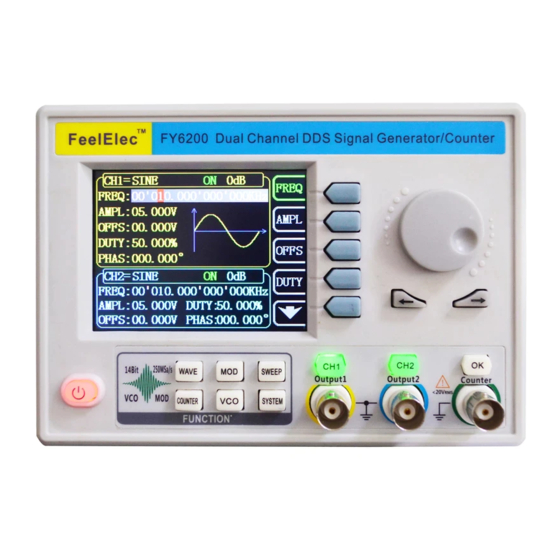
User Interface The user interface of fy6200 includes four display modes: dual channel parameter display mode, single channel extended display mode, additional function display mode and system configuration display mode. Dual Channels Parameters The upper half of LCD displays the channel selected currently and the parameters can be set. - Page 15 FeelElec Currently selected channel output status bar The current channel output on / off status is displayed, and the output status can be changed by adjusting the front panel channel control buttons CH1 and CH2. Waveform Display diagram of current waveform(Including Arbitrary).
-
Page 16: Dimensions
Dimensions... -
Page 17: Front Panel Operations
Front Panel Operations Waveform Output FY6200 series can output waveforms (Sine, Square, Triangle/Ramp, Pulse and Noise etc.) from one of the channels separately or from the two channels at the same time. At start-up, the dual channels are configured to output a sine waveform with 10kHz frequency and 5Vpp amplitude by default. -
Page 18: Select Waveform
√ Phase √ √ √ √ √ Duty Cycle √ Note: the user-defined waveform can be edited and downloaded through the fy6200 upper computer control software provided by feelelec. Relevant software and drivers can be downloaded from our website: http://www.feelelec.com... -
Page 19: Selevct Frequency
FeelElec Set Frequency Frequency is one of the most important parameters of the basic waveform. The frequency can be set differently based on different signals and different waveforms. Please refer to the description of “Frequency Characteristics” in “Performance Specifications”. The factory default setting is 10KHz. -
Page 20: Set Amplitude
Set Amplitude The settable range of amplitude is limited by the "frequency" setting. Please refer to the description of "output characteristic" in "performance index". The default is 5vpp. Press the FREQ soft key to highlight the amplitude parameter. At this time, use the direction key and the adjustment knob to set the value of the amplitude: use the direction key to move the cursor to select the position to be edited, and then rotate the knob to modify the value. -
Page 21: Set Offset
FeelElec Set Offset Press the OFFS key to highlight the offset parameter. At this time, use the direction key and adjustment knob to set the offset value: use the direction key to move the cursor to select the position to be edited, and then rotate the knob to modify the value. -
Page 22: Set Duty Cycle(Square)
Set duty cycle (square wave) Duty cycle is defined as the percentage of the duration of the high level of the square wave in the cycle, as shown in the figure below. This parameter is only valid when square wave is selected. The setting range of duty cycle is limited by the “FREQ”... -
Page 23: Set Phase
FeelElec positive pulse width t greater than or equal to the period T length of the output waveform). Set Phase The initial phase can be set from 0 ° to 359.99 ° and the phase resolution is 0.01 ° . The default value is 0 ° . -
Page 24: Enable Channel Output
Enable channel output After completing the parameter settings for the selected waveform, you need to turn on the channel to output the waveform. When the output is off, the LED below the corresponding channel button is off; when the output is on, the LED is lit. -
Page 25: Example: Output Sine Waveform
FeelElec Example: output sine wave This section mainly introduces how to output a sine wave from the [ch1] connector (frequency 20KHz, amplitude 2.5vpp, offset 1.6vdc, initial phase 90.9 ° ) 1. Select output channel: Press CH1 to select CH1. Now all characters and border of the channel is displayed in yellow. -
Page 27: Digital Modulation
FeelElec Modulation function Press the MOD key on the front panel to enable the modulation function, and fy6200 can output the modulation waveform from ch1 channel. This function uses ch1 waveform signal as carrier, CH2 waveform signal, external signal or manual pulse signal as modulation wave to modulate signal. - Page 28 Modulation mode Click the < F1 > mode key under the modulation function to switch the modulation modes, including ① FSK (frequency keying) ② ASK (amplitude keying) ③ PSK (phase keying). ④ Trigger (controllable burst output). ⑤ AM (Amplitude Modulation). )...
- Page 29 FeelElec Modulation source Under the modulation function, click the <F2> source button to switch the modulation source, that is to say, select the modulation signal. In FSK, ASK, PSK and Trigger modes, there are four sources: ① CH2: Channel 2 signal as modulation signal ②...
- Page 30 Modulation parameter Click the < F3 > parameter key under the modulation function to adjust the modulation parameters. For Example: ① In the "FSK" mode, the frequency of frequency hopping can be adjusted. ② In the "trigger" mode, the number of output pulse trains can be adjusted. ③...
- Page 31 FeelElec Pulse string The FY6200 can output a waveform with the specified number of cycles from the CH1 channel (called burst, Burst). Fy6200 supports the output of pulse strings controlled by CH2 internal, manual or external trigger sources; the signal generator can use sine wave, square wave, sawtooth wave, pulse, noise wave or any wave (except DC) to generate pulse strings.
-
Page 32: Frequency Meter/Counter
Frequency meter/counter FY6200 provides the function of frequency meter/counter, which can measure the frequency, period, duty cycle, positive pulse width, negative pulse width and other parameters of external input signal. Dual channel output can work simultaneously with the frequency meter measurement. Enable frequency meter Press COUNTER on the front panel to open the function of frequency meter and display the setting interface of frequency meter. -
Page 33: Set The Counter
FeelElec Set frequency meter Gate Time Press the GATE soft key to select the gate time of the measurement system. The default is 1s. When measuring low frequency signal, 10s or 100s gate time can be selected. Strobe time Frequency resolution 0.1Hz... -
Page 34: Sweep
Sweep Press the SWEEP key on the front panel to enable the scanning function, and fy6200 can output the scanning waveform from ch1 channel. The process of gradient scanning for a specific parameter object at a specified time from the initial value to the termination value. - Page 35 FeelElec Scanning start position After the "Sweep" function key is enabled, the scan start value needs to be set according to the scan object. ⚫ Frequency scanning: press the STAR soft key to highlight the "start" parameter, press the direction key and rotate the adjustment knob to adjust to the start value specified by the user, as shown in the following example.
-
Page 36: Sweep Start Position
Sweep end position When the sweep function key is enabled, you need to set the scan cut-off value according to the scan object. ⚫ Frequency scanning: press the END soft key to highlight the "cut-off" parameter, press the direction key and rotate the adjustment knob to adjust to the cut-off value specified by the user, as shown in the following example. -
Page 37: Sweep Type
FeelElec Sweep Type FY6200 provides two types of scanning: linear scanning and logarithmic scanning. The default is linear scanning. In the scan interface, press the mode soft key to switch. Linear sweep Under the linear scanning mode, the parameters of the output signal of the instrument change linearly. -
Page 38: Enable Frequency Sweep Function
Enable frequency sweep function: Press the SWEEP key on the front panel to enable the frequency sweep function, press the OK key to start the scanning process, and press the OK key again to stop the scanning. Initial value and cut-off value Initial and cut-off values are the upper and lower bounds of parametric scanning. - Page 39 FeelElec VCO Sweep Function Function introduction: The signal output of the external voltage control signal generator can be realized by external scanning (VCO function). This function can be realized: voltage control frequency (VCF), voltage control amplitude (VCA), voltage control bias, voltage control duty cycle function.
-
Page 40: System Setup And Auxiliary Functions
System settings and auxiliary functions Press the SYSTEM key on the front panel to open the operation interface shown in the figure below. This interface displays the function information of instrument parameter storage, parameter loading, synchronization, configuration, etc. ⚫ SAVE:The current waveform parameters can be stored in 20 groups of storage areas of the system. -
Page 41: Storage And Loading
FeelElec SAVE and LOAD In the system interface, press the SAVE soft key to store the information of the current system waveform in the specified storage location; press the LOAD soft key to load the previously stored system waveform parameter information into the current system status. -
Page 42: Configuration
Configuration Press the【SYSTEM】key to enter the system interface, press the SYSTEM soft key to enter the system configuration interface, press the right parameter soft key to set the system's working mode. ⚫ Press the 中文 soft key and select the system prompt language as Chinese. ⚫... -
Page 43: Uplink
FeelElec Synchronization function After pressing the【SYSTEM】button, press the【Sync】soft key to enter the synchronization function setting interface. Press the right parameter soft key to switch it in the selected (highlighted) / canceled state. When the synchronization of the corresponding parameters is turned on, the corresponding parameter of CH2 changes according to the change of CH1, and no human intervention is required. -
Page 44: Fault Handling
If you are still unable to use the product properly, please contact FeelElec. 1) Check whether the signal generator works in synchronous state. Press the SYSTEM button -> Signal generator CH2 locked SYNC to enter the synchronization setting interface to cancel all synchronization parameters. -
Page 45: Technical Indicator
FeelElec Technical Index Unless otherwise stated, all technical specifications are guaranteed when the following two conditions are met. ⚫ The signal generator is in the pass-through state. ⚫ The signal generator runs continuously for more than 30 minutes at the specified operating temperature (18 °... - Page 46 overshoot ≤5% Square and Pulse wave Duty cycle adjustment range 0.01%~99.99% (Resolution 0.01%) Sawtooth wave linearity ≥98% (0.01Hz~10kHz) Output characteristics 10MHz<Frequency Frequency≤10MHz Frequency>20MHz Amplitude(VPP) ≤20MHz 1mVpp~20Vpp 1mVpp~10Vpp, 1mVpp~5Vpp Amplitude Resolution Amplitude Stability ± 0.5%/ 5 hours Amplitude flatness ± 5%(<10MHz);± 10%(>10MHz); Waveform Output Output Impedance 50Ω±10%(Typical)...
- Page 47 FeelElec Counting range 0-4294967295 Counter function counting mode Manual Maximum measurable Pulse width measurement 10ns Resolution, Maximum measurable Cycle measurement 10ns Resolution, Sweep Function Carrier waveform Sine wave, square wave, sawtooth wave, arbitrary wave (excluding DC voltage) Sweep Type Linear sweep, logarithmic sweep...
- Page 48 Source Internal(CH2) Manual Modulation Waveform 50% Duty Cycle square wave 1μHz~10MHz Keying frequency Source Internal(CH2) Manual Modulation Waveform 50% Duty Cycle square wave 1μHz~10MHz Keying Frequency Source Internal(CH2) Manual Modulation Waveform 50% Duty Cycle square wave 1μHz~10MHz Keying Frequency Burst Function Carrier waveform Sine wave, square wave, triangle wave, sawtooth wave, arbitrary wave (except DC voltage) Pulse Count...
-
Page 49: Appendix
Appendix C: accessories and options Description 数量 Main FY6200 series signal generator Frame DC5V DC power supply USB cable Standard Transfer clip cable (Q9 clip cable)
Need help?
Do you have a question about the FY6200 Series and is the answer not in the manual?
Questions and answers