Table of Contents
Advertisement
Quick Links
Advertisement
Table of Contents

Summary of Contents for Gamry eQCM 10M
- Page 1 Impedance Scanning Electrochemical Quartz Crystal Microbalance...
- Page 3 Impedance Scanning Electrochemical Quartz Crystal Microbalance Operator's Manual Copyright 2012 Gamry Instruments, Inc. Revision 1.2 August 27, 2012...
- Page 4 If You Have Problems Please visit our service and support page at www.gamry.com/service-support/. This page contains information on installation, software updates, and training. It also contains links to the latest available documentation. If you are unable to locate the information you need from our website, you can contact us via email using the link provided on our website.
- Page 5 Limited Warranty Gamry Instruments, Inc. warrants to the original user of this product that it shall be free of defects resulting from faulty manufacture of the product or its components for a period of two years from the original shipment date of your purchase.
-
Page 6: Copyrights
Reference 600, Reference 3000 , PC4, PCI4, eQCM 10M, Gamry Framework, PHE200, and Gamry are trademarks of Gamry Instruments, Inc. No part of this document may be copied or reproduced in any form without the prior written consent of Gamry Instruments, Inc. -
Page 7: Table Of Contents
Disclaimers ............................vi Copyrights .............................vi Chapter 1 -- Safety Considerations ....................1-1 Inspection.........................1-1 Product Safety ........................1-1 AC Mains Connection to the Power Brick ................1-1 Grounding in the eQCM 10M ...................1-2 Temperature and Ventilation.....................1-2 Defects and Abnormal Stresses ..................1-3 Environmental Limits......................1-3 Cleaning ...........................1-3 Service..........................1-3 Emission Warning ......................1-4... -
Page 9: Chapter 1 -- Safety Considerations
EN 61010 (the standard mentioned above). “Reinforced insulation” (again defined in EN 61010) is used to reduce the risk of electrical shock due to this “hazardous live” voltage. As a generalization, input and output voltages in the eQCM 10M are limited to 12 volts. This voltage level is considered safe. -
Page 10: Grounding In The Eqcm 10M
Grounding in the eQCM 10M A Chassis Ground binding post on the rear panel of the eQCM 10M is provided for a connection to earth ground. Simply run a wire from this binding post to a suitable source of earth ground. A black 1.2-meter wire is provided to facilitate this connection. -
Page 11: Defects And Abnormal Stresses
• it has been subjected to environmental stress (corrosive atmosphere, fire, etc.). • Do not use your eQCM 10M or any other apparatus if you think it could be hazardous. Have it checked by qualified service personnel. Environmental Limits Note that there are environmental limits conditions on the storage, shipping and operation of this equipment. -
Page 12: Emission Warning
The radiated levels are low enough that the instrument should not create an interference problem in most industrial laboratory environments. The eQCM 10M has been tested for both radiated and conducted RF interference and has been found to be in compliance with EN 50081-1, 55011, and 55022 and 61000-4-3. -
Page 13: Chapter 2 -- Introduction
Chapter 1 was an in-depth discussion of safety issues. This chapter describes this manual and gives a brief overview of the eQCM 10M features. Chapter 3 is a description of the electronics circuitry in the eQCM 10M. Chapter 4 contains installation instructions. Chapter 5 describes inserting a crystal into a holder and connecting the holder to the eQCM 10M and Chapter 6 describes the eQCM 10M’s Front and Rear Panels. - Page 14 Chapter 2 -- Introduction--Notational Conventions 2 - 2...
-
Page 15: Chapter 3 -- Instrument Circuitry
Chapter 3 -- Instrument Circuitry--eQCM 10M Schematic/Block Diagram Chapter 3 -- Instrument Circuitry eQCM 10M Schematic/Block Diagram If you are not familiar with electronic schematics or quartz crystal microbalances, you probably want to skip this chapter. This information is for expert use only and is not required for routine use of the instrument. - Page 16 Chapter 3 -- Instrument Circuitry--eQCM 10M Schematic/Block Diagram The coupler allows integration to a potentiostat for electrochemical studies. The output signal from the • crystal is coupled out by the same network. The signal is then passed through an RMS-to-DC (TRMS) converter and evaluated by a successive approximation A/D-converter (ADC).
-
Page 17: Chapter 4 -- Installation
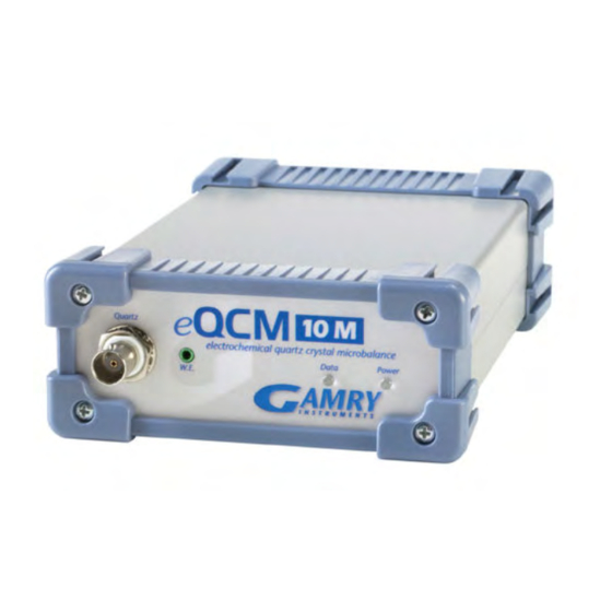
View of an eQCM 10M Initial Visual Inspection After you remove your eQCM 10M from its shipping carton, you should check it for any signs of shipping damage. If any damage is noted, please notify Gamry Instruments, Inc. and the shipping carrier immediately. -
Page 18: Physical Location
Physical Location You normally locate your eQCM 10M on a flat workbench surface. You will want to have access to the rear of the instrument because some cable connections are made from the rear. The eQCM 10M is generally operated in a horizontal position (see Figure 4-1). -
Page 19: Power Cord And Power Connection
Before you make any other connections to your eQCM 10M you should check that the instrument is at least nominally functional. One quick test is to power up the eQCM 10M and watch the blue power LED indicator on the front panel (see Figure 4 - 1). -
Page 20: Usb Cabling
Chapter 4 -- Installation--USB Cabling If the power LED goes on, then turns off and does not come on, the eQCM 10M is not working properly! Contact Gamry Instruments or your local Gamry Instruments representative as soon as possible if this power up test fails. -
Page 21: St Time Device Installation In Windows
Windows Plug and Play Manager will see the new device, but will be uncertain what device it is. The message that will appear is something like “New device found” or “Unknown USB device Detected”. When this occurs after you’ve connected an eQCM 10M, tell Windows that you would like to install the new device. - Page 22 The Windows Device Manger will install the required files from the CD. On occasion you may desire to change the USB port which is used to connect the eQCM 10M to your computer. The same procedure discussed above may need to be followed for each USB port on your computer, depending upon your operating system requirements.
-
Page 23: Device Manager
Device Manager If you wish to make changes to the configuration of your eQCM 10M after it has already been installed, you must use the Windows Device Manager. Steps for getting to the Device Manager can vary by operating system, so check your operating system’s online help for more specific information on how to get to the Windows... - Page 24 Device Properties If you are interfacing the eQCM 10M to a Gamry Potentiostat you will need to enter in the necessary 10-digit authorization code into the Device Settings tab for your potentiostat. Click on Add to bring up a dialog box...
-
Page 25: Chapter 5 -- Cell Connections
Normal Cell Connections Each eQCM was shipped with a standard, shielded BNC cable terminated with a ceramic adapter. The Gamry part number for this cable is 985-00124. The male end of the cable gets attached to the front panel of the eQCM 10M (see Figure 5.1). -
Page 26: Quartz Crystal Installation
Chapter 5 -- Cell Connections--Quartz Crystal Installation Quartz Crystal Installation Place a clear plastic insulator on the quartz crystal and attach the adapter (see Figures 5.2 and 5.3). Figure 5 - 2 Crystal with Plastic Insulator Figure 5 - 3 Connection of Metal Adapter Next, place the crystal, with the working face upward, on the bottom of the Teflon cell (see Figure 5.4). - Page 27 Chapter 5 -- Cell Connections--Quartz Crystal Installation Figure 5 - 4 Placement of Crystal and Holder on Cell Bottom Place the main body of the cell over top of the crystal, invert, and use the four supplied screws to hold the bottom and body of the cell together (see Figure 5.5).
- Page 28 Connection of Working (Green) and Working Sense (Blue) Leads to Crystal A binding post on the rear panel of the eQCM 10M is provided for grounding purposes. A water pipe can be a suitable source of earth ground or an AC mains ground is also suitable.
- Page 29 Make sure that your earth ground connection is made to a legitimate source of earth ground. Consult a qualified electrician if you are uncertain how to obtain an earth ground. Connecting the eQCM 10M to an incorrect and unsafe voltage can create a safety hazard (see Chapter 1 for details).
-
Page 31: Chapter 6 -- Panel Indicators And Connectors
It is normally used with a Gamry Instruments supplied cell cable. The Power LED The Power LED is located on the right of the eQCM 10M front panel. It normally glows a steady blue when the eQCM 10M is turned on. -
Page 32: Chassis Ground
USB Port The USB port on the rear panel of the eQCM 10M is a Type B connector as defined in Revision 1.1 and 2.0 of the USB Specification. You use a standard, shielded, Type A/B cable to connect this port to a computer’s USB port or a USB hub (preferably an externally powered hub). -
Page 33: Appendix A - Eqcm 10M Specifications
Appendix A – eQCM 10M Specifications-- Appendix A – eQCM 10M Specifications All specifications are subject to change without notice. Frequency Measurement Range 1 – 10 Resolution 0.02 Environmental Operating Temperature Range 0 to 45 °C Relative Humidity 90 (non-condensing) -
Page 34: Appendix B - Ce Certificate
According to ISO/IEC Guide 22 and CEN/CENELEC EN 45014 Manufacturer's Name and Location: Gamry Instruments 734 Louis Drive Warminster, PA 18974 This declaration is for the Gamry Instruments product models: eQCM 10M. The declaration is based upon compliance with the following directives: EMC Standards Title Class/ Criteria EN 61000-4-2 EMC –... -
Page 35: Comprehensive Index
Comprehensive Index-- storage, 1-3 Comprehensive Index support, iv AC adapter, 1-1 telephone assistance, iv CE Compliance, 1-4 USB cable, 4-4 cell cable, 5-1 USB port, 6-2 Chassis Ground, 6-2 cleaning, 1-3 ventilation, 4-2 computer, 2-1 Visual Inspection, 4-1 computer requirements, 4-2 contract engineering, iv Warranty, v conventions...
Need help?
Do you have a question about the eQCM 10M and is the answer not in the manual?
Questions and answers