Table of Contents
Advertisement
Advertisement
Table of Contents

Related Manuals for AHRI SUPERIOR Series


Summary of Contents for AHRI SUPERIOR Series
- Page 1 SK2018 PCG(H)-V/P-AECM-001...
-
Page 2: Sk2018 Pcg(H)-V/P-Aecm
Page 1 of 83 INVESTING IN QUALITY, RELIABILITY & PERFORMANCE ISO 9001 QUALITY World Leading Design and Technology Every product is manufactured to meet Equipped with the latest air-conditioning test rooms the stringent requirements of the and manufacturing technology, we produce over internationally recognized ISO 9001 50,000 fan coil units each year, all conforming to the standard for quality assurance in design,... -
Page 3: Table Of Contents
Page 2 of 83 Table of Contents A. Technical Data ................................6 General Description ..............................6 General Specification ..............................7 2-Pipe Systems ..............................7 4-Pipe Systems ..............................9 Coil Data ..................................10 Sound data ................................. 11 Dimensional Drawings of 2-Pipe Unit ........................17 Dimensional Drawings of 4-Pipe Unit ........................ - Page 4 Page 3 of 83 Wiring Diagram ................................. 46 Standard S Control PCB ............................46 Master Slave Networking Wiring Diagram ......................47 Configuration Settings ............................... 48 Fan Coil Unit ON/OFF ............................49 Auto Restart ................................ 49 Control Logic For 2-Pipe System ..........................50 With Valve Configuration ............................
- Page 5 Page 4 of 83 G. User Interface ................................76 Remote Handset ................................ 76 Wired Wall Pad Controller ............................77 H. Sensor Resistance R-T Conversion Table ........................81 I. Troubleshooting ................................83 SK2018 PCG(H)-V/P-AECM-001...
- Page 6 Page 5 of 83 Model Code Nomenclature - 04 - V - S - AECM AECM EC motor configuration Complete function on board PCB with integrated group control functionality Flexible function on board PCB with drain pump, louver and zone control functionality No control box pre-installed 220V EC motor 115V EC motor...
-
Page 7: Technical Data
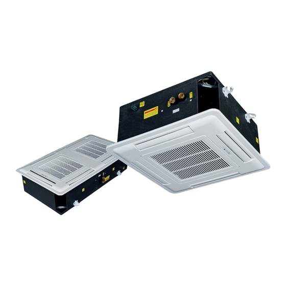
Page 6 of 83 A. Technical Data A.1. General Description The Ceiling cassette units make each served area an independent controlled temperature zone to suit diverse requirements. Construction Cases are constructed of galvanized sheet steel with integral fan mounting rails for added strength. Fire resistant insulation is fitted internally to provide both thermal and acoustic insulation. -
Page 8: General Specification
Page 7 of 83 A.2. General Specification A.2.1. 2-Pipe Systems Product range: PCG(H) -AECM Flexi Hydronic Cassette with EC Motor PCG(H)-V~-AECM Hydronic Cassette 2-pipe with EC Motor PCG(H)-[Size]-V~-AECM PCG-04R PCG-08 PCG-08R PCG-09 Configuration 2-pipe Number Of Fan Blowers Single Twin 115/1/60 Power Supply (V/Ph/Hz) - Page 9 Page 8 of 83 Product range: PCG(H) -AECM Flexi Hydronic Cassette with EC Motor PCG(H)-V~-AECM Hydronic Cassette 2-pipe with EC Motor PCG(H)-[Size]-V~-AECM PCG-16 PCH-12 PCH-20 Configuration 2-pipe Number Of Fan Blowers Twin Single 115/1/60 Power Supply (V/Ph/Hz) 220/1/60 ~S: Complete function on board PCB with integrated group control functionality.
-
Page 10: 4-Pipe Systems
Page 9 of 83 A.2.2. 4-Pipe Systems Product range: PCG(H) -AECM Flexi Hydronic Cassette with EC Motor PCG(H)-P~-AECM Hydronic Cassette 4-pipe with EC Motor PCG(H)-[Size]-P~-AECM PCG-08 PCG-09 PCG-16 PCH-12 PCH-20 Configuration 4-pipe Number Of Fan Blowers Single Twin Single 115/1/60 Power Supply (V/Ph/Hz) 220/1/60... -
Page 11: Coil Data
Page 10 of 83 A.3. Coil Data 2-Pipe Systems Fin Length No. of Tube Model Fin Height Fins / inch No. of rows circuits Diameter Inner Outer PCG-04-V 7-7/8 47-1/16 51-1/8 Ø3/8 PCG-08-V 9-13/16 47-1/16 51-1/8 Ø3/8 PCG-08R-V 9-13/16 47-1/16 51-1/8 Ø... -
Page 12: Sound Data
Page 11 of 83 A.4. Sound data Sound Power Model PCG-04-AECM Speed H(570) M (450) L(250) 200RPM 300RPM 400RPM 500RPM 600RPM 700RPM 800RPM 900RPM 1000RPM Sound Power 52.3 46.3 36.8 36.8 38.8 42.8 49.2 53.3 56.4 60.4 62.4 64.6 dB(A) 20.0 11.7 16.1... - Page 13 Page 12 of 83 Model PCG-08-AECM speed H(900) M(560) L(250) 100RPM 200RPM 300RPM 400RPM 500RPM 600RPM 700RPM 800RPM 900RPM 1000RPM Sound Power 59.2 45.8 32.8 31.6 32.9 33.1 37.6 43.2 47.8 52.0 55.6 59.2 62.5 dB(A) 20.0 18.6 14.2 16.0 14.3 15.9 10.7...
- Page 14 Page 13 of 83 Model PCH-12-AECM Speed H(860) M(620) L(350) 200RPM 300RPM 400RPM 500RPM 600RPM 700RPM 800RPM 900RPM 1000RPM Sound Power 63.3 54.8 40.8 34.6 37.2 44.2 51.5 54.5 57.7 61.6 66.6 68.9 dB(A) 20.0 11.8 15.3 10.3 11.0 10.2 11.8 16.2 13.9...
- Page 15 Page 14 of 83 Model PCH-20-V-AECM Speed H(930) M(650) L(400) 200RPM 300RPM 400RPM 500RPM 600RPM 700RPM 800RPM 900RPM 1000RPM Sound Power dB(A) 67.8 57.5 43.9 34.8 36.1 43.3 50.9 55.7 59.9 63.3 66.9 68.5 20.0 10.4 11.4 -1.9 12.9 11.1 23.5 15.7 25.0...
- Page 16 Page 15 of 83 Model PCG-09-AECM Speed 200RPM 300RPM 400RPM 500RPM 600RPM 700RPM 800RPM 900RPM 1000RPM (570) (450) (250) Sound Power dB(A) 55.3 49.3 39.8 39.8 41.8 45.8 52.2 56.3 59.4 63.4 65.4 67.6 14.7 19.1 17.3 15.1 18.2 22.3 15.9 19.9 22.3...
- Page 17 Page 16 of 83 Model PCG-16-AECM Speed H(900) M(560) L(250) 100RPM 200RPM 300RPM 400RPM 500RPM 600RPM 700RPM 800RPM 900RPM 1000RPM Sound Power 63.2 49.8 36.8 35.6 36.9 37.1 41.6 47.2 51.8 59.6 63.2 66.5 dB(A) 22.6 18.2 18.3 19.9 14.7 16.3 18.1 17.3...
-
Page 18: Dimensional Drawings Of 2-Pipe Unit
Page 17 of 83 A.5. Dimensional Drawings of 2-Pipe Unit Model PCG-04-V-AECM 26-3/4 22-15/16 24-11/16 2-7/16 4-7/8 10-1/16 PCG-08,08R-V-AECM 26-3/4 22-15/16 24-11/16 4-7/16 6-7/8 11-7/16 PCH-12-V-AECM 32-11/16 28-3/4 13-9/16 30-1/2 3-5/16 5-7/8 10-1/4 PCH-20-V-AECM 38-9/16 32-11/16 19-3/16 34-7/16 4-3/16 11-7/16 Model PCG-04-V-AECM 11-1/8... - Page 19 Page 18 of 83 Model PCG-09-V-AECM 26-3/4 48-13/16 45-1/16 29-1/2 24-13/16 Φ3-15/16 20-1/2 PCG-16-V-AECM 26-3/4 48-13/16 45-1/16 29-1/2 24-13/16 Φ3-15/16 20-1/2 Model PCG-09-V-AECM 4-13/16 2-7/16 4-7/8 10-1/16 11-1/8 4-5/8 PCG-16-V-AECM 5-5/16 4-7/16 6-7/8 11-7/16 12-1/2 4-5/8 (All dimensions are approximate within 1/16 of an inch of those indicated.) SK2018 PCG(H)-V/P-AECM-001...
-
Page 20: Dimensional Drawings Of 4-Pipe Unit
Page 19 of 83 A.6. Dimensional Drawings of 4-Pipe Unit Model PCG-08-P-AECM 26-3/4 22-15/16 24-11/16 4-7/16 6-7/8 11-7/16 12-1/2 PCH-12-P-AECM 32-11/16 28-3/4 13-9/16 30-1/2 3-5/16 5-7/8 10-1/4 11-5/16 PCH-20-P-AECM 38-9/16 32-11/16 19-3/16 34-7/16 4-3/16 11-7/16 12-1/2 Model PCG-08-P-AECM 4-5/8 4-5/16 6-3/8 6-7/8 Φ3-15/16... - Page 21 Page 20 of 83 Model PCG-09-P-AECM 26-3/4 48-13/16 45-1/16 29-1/2 24-13/16 Φ3-15/16 20-1/2 PCG-16-P-AECM 26-3/4 48-13/16 45-1/16 29-1/2 24-13/16 Φ3-15/16 20-1/2 Model PCG-09-P-AECM 2-3/4 3-3/8 2-7/16 4-7/8 10-1/16 11-1/8 4-5/8 PCG-16-P-AECM 2-3/4 4-5/16 4-7/16 6-7/8 11-7/16 12-1/2 4-5/8 (All dimensions are approximate within 1/16 of an inch of those indicated.) SK2018 PCG(H)-V/P-AECM-001...
-
Page 22: Valve Information (Optional Parts)
Page 21 of 83 A.7. Valve Information (Optional parts) 2-Way Valve Body Valve Body Dimensions (inch) Valve Code (valve body + ON/ OFF thermoelectric actuator) SGS14HFCA-23010201 2-3/16 1-7/8 2-1/2 (G3/4”) 3-Way Valve Body Valve Body Dimensions (inch) Valve Code (valve body + ON/ OFF thermoelectric actuator) SGS14HFCA-23010202 2-3/16 3-7/16... - Page 23 Page 22 of 83 Actuator Model DR-16-115B DR-16-24B DR-15B-24B Normal closed Normal closed Normal closed Voltage 115Vac 24Vac 24Vac Working force 90~125N 90~125N 90~125N Time 4.5min 4.5min 4.5min Power Full stroke 3.5mm 3.5mm 5.0mm Imax 150mA 250mA 250mA Wires 2-wire 2-wire 3-wire (red, blue, black) SK2018 PCG(H)-V/P-AECM-001...
-
Page 24: Installation
Page 23 of 83 B. Installation B.1. Safety Precautions When installing, performing maintenance or servicing Polar Air fan coil units observe the • precautions stated in this manual as well as those stated on the labels attached to the unit. Ensure all local and national safety codes, laws, regulations, as well as general electrical and •... -
Page 25: Standard Configurations And Accessories
Page 24 of 83 B.2. Standard Configurations and Accessories First check the contents of the package. There are three types of plug-and-play control box: Plug-and-play control box – S1 Type PCG(H)-(V/P)S configuration – Complete function integrated controller, compatible with IR handset controller, wired wall- pad, serial networking for master-slave and MODBUS applications. -
Page 26: Operating Limits
Page 25 of 83 B.3. Operating Limits Power supplies Code Volt Phase Water circuit Minimum entering water temperature 35.6 °F Maximum entering water temperature 176 °F Coil tested maximum pressure 232 psi B.4. Before Installation The installation site must be established by the system designer or other qualified professional, taking account of the technical requisites and current standards and regulations. -
Page 27: Installation Location
Page 26 of 83 B.5. Installation Location Do not install the unit in rooms where flammable gas or alkaline acid substances are present. Aluminum/copper coils and/or internal plastic components can be damaged irreparably. Do not install in workshops or kitchens; drawn in oil vapors might deposit on the coils and alter their performance or damage the internal plastic parts of the unit. -
Page 28: Condensate Drainage Connection
Page 27 of 83 B.7. Condensate Drainage Connection The unit is fitted with a condensate pump with a maximum of 19-11/16” lift. Confirm drain outlet has not been damaged before connecting drain pipe to unit. Discharge pipe may be connected with hose clamp. (Figure B.7.1) ... -
Page 29: Water Connections And Valve Configurations
Page 28 of 83 B.9. Water Connections and Valve Configurations The cassette unit uses is provided with 3/4” water piping connections with gaskets. ~S: Units are compatible with: 2-way and 3-way on/off valves (thermoelectric or electric motor-driven actuation), with OPEN/CLOSE state actuation. ... -
Page 30: Fresh Air Renewal Connection
Page 29 of 83 B.10. Fresh Air Renewal Connection The fresh air system for cassette unit allows up to 15% of airflow (maximum air flow per connection is 100m /h) to be fresh air intake (per connection). Maximum 2 fresh air connections per unit are allowed. 1. - Page 31 Page 30 of 83 Figure B.10.4 Figure B.10.5 Fresh Air Flange dimension (All dimensions are approximate within 1/16 of an inch of those indicated.) SK2018 PCG(H)-V/P-AECM-001...
-
Page 32: Branch Duct Connection
Page 31 of 83 B.11. Branch Duct Connection The side opening allows branch duct work to be installed. Dimensions and location for connection are shown in Figure B.11.1 and Figure B.11.2. Flanges and conduits can be installed to casing. ... -
Page 33: Suspension Bolts Layout And Ceiling Opening
Page 32 of 83 B.12. Suspension Bolts Layout and Ceiling Opening Using installation template, remove and/or modify the ceiling panels and install the suspension bolts as the images below. PCG-04R/08/08R~ 23-5/8 x 23-5/8: Dimensions for opening 24-1/2 x 11: Suspension Bolts PCG-09/16~ 45-11/16 x 23-5/8: Dimensions for opening 29-1/2 x 24-7/8: Suspension Bolts... - Page 34 Page 33 of 83 PCH-12~ 29-1/2 × 29-1/2: Dimensions for opening 13-9/16 × 30: Suspension Bolts PCH-20~ 33-7/16 × 33-7/16: Dimensions for opening 19-1/16 × 34: Suspension Bolts (All dimensions are approximate within 1/16 of an inch of those indicated.) SK2018 PCG(H)-V/P-AECM-001...
- Page 35 Page 34 of 83 Installation Procedures: 1. Lift unit (without front panel) with care by four corners only. Do not lift unit by the condensate drain discharge pipe or piping connections. 2. Incline the unit and insert it into ceiling. Insert support rods into the bracket slot. 3.
- Page 36 Page 35 of 83 For Twin Fan Unit: SK2018 PCG(H)-V/P-AECM-001...
-
Page 37: Electrical Connection
Page 36 of 83 B.13. Electrical Connection It is recommended shielded line voltage and low voltage cables in electrically noisy areas. Do not install fan coil unit in a location where electromagnetic waves may be directly emitted towards infra-red receiver ... -
Page 38: Mounting Front Panel Assembly
Page 37 of 83 B.14. Mounting Front Panel Assembly Remove return grille from front panel. Move the front panel to the unit casing. Tighten 4 screws to attach the front panel as shown in Figure B.14.1 and Figure B.14.2. The front panel does not move upwards excessively because the screws are not fully threaded (see below Figure B.14.3). - Page 39 Page 38 of 83 5. Ensure that voltage and current values correspond with the unit nameplate values; check electrical connections. 6. Verify louver is open. SK2018 PCG(H)-V/P-AECM-001...
-
Page 40: Maintenance
Page 39 of 83 C. Maintenance Turn off the main power switch before performing any service or maintenance operations. Please see section B.1. “Safety Precautions”. The air filter is made of acrylic fiber and is washable in water. Open the intake grille by releasing the two fasteners to remove filter. -
Page 41: Filter Removal
Page 40 of 83 C.3. Filter Removal 1. Unlock the two fasteners on the front panel. 2. Open the grille downward with care. 3. Pull the filter out along the slot. 4. Clean the filter and reassemble. C.4. Air Vent and Water Purge Valve Step 1: Remove grille, access the area Step 2:... -
Page 42: Fan Speed Customization
Page 41 of 83 C.5. Fan Speed Customization Step 1: Remove grille to access the connection wires area. Step 2: Remove the 4 screws of the inner grille. Step 3: Remove inner grille and venture Step 4: Locate the Fan Speed Terminal as red line indicated. Step 6: The 3 output wires from Control PCB for fan speed Step 5: Customize fan speed by rewiring the terminal block (labeled LF / MF / HF) may be rewired to any of the 5 input... -
Page 43: Motor And Fan Blower Replacement
Page 42 of 83 C.6. Motor and Fan Blower Replacement Refer to Section C.5. for Steps 1, 2 and 3. Wire connector Mounting bolt Step 4: Use a spanner to remove the fan blower. Step 5: Remove motor by undoing the 4 bolts. Disconnect wire connector and replace the motor. -
Page 44: Control Box Replacement
Page 43 of 83 C.8. Control Box Replacement Refer to Section C.5. for Steps 1, 2 and 3. Step 5: Remove the terminal cover by undoing the 4 Step 4: Remove 2 screws from the control box and screws. Disconnect wiring on the terminal. Replace slide it out. - Page 45 Page 44 of 83 REMARKS If the cassette is installed with an Electric Heater, do not select motor speed 1 as LF on the control PCB. Refer to C.5. to change motor speed. SK2018 PCG(H)-V/P-AECM-001...
-
Page 46: Control Specifications: Complete Control Pcb - Ec-S1 Control
Page 45 of 83 D. Control Specifications: Complete Control PCB – EC-S1 Control Abbreviations Ts = Setting temperature AUX1 = Hot water free contact Tr = Room air temperature AUX2 = Chilled water free contact Ti1 = Chilled water coil temperature MTV1 = Chilled water valve Ti2 = Hot water coil temperature MTV2 = Hot water valve... -
Page 47: Wiring Diagram
Page 46 of 83 D.2. Wiring Diagram D.2.1. Standard S Control PCB NA-AEC-S1-unit wiring scheme AEC-S1-2018 IPA-S1 SW1-5: set the unit address SW6: set unit type: master or slave Mode Configuration SW7=0;SW8=0; unit operates in cooling/heating SW7=0;SW8=1; unit operates in cooling/heating with booster EH SW7=1;SW8=0;... -
Page 48: Master Slave Networking Wiring Diagram
Page 47 of 83 D.2.2. Master Slave Networking Wiring Diagram Master Unit Slave Unit Connect to other slave units SK2018 PCG(H)-V/P-AECM-001... -
Page 49: Configuration Settings
Page 48 of 83 D.3. Configuration Settings DIPA-S1 DIPB-S2 SW1-SW5 Network address setting SW5/SW6 Fan Qty setting SW5=0 Single fan application SW6=1 SW5=1 Twin fans application Master / Slave setting SW6=1 SW6=1 Master SW6=0 Slave Preheat temperature setting SW4=1 28ºF SW4=0 36ºF SW7/SW8 Operating mode... -
Page 50: Fan Coil Unit On/Off
Page 49 of 83 D.3.1. Fan Coil Unit ON/OFF There are 3 ways to turn the system on or off: a) By the ON/OFF button on the remote handset or wired wall pad; b) By the programmable timer on the handset or wired wall pad. c) By the manual control button on fan coil unit. -
Page 51: Control Logic For 2-Pipe System
Page 50 of 83 D.4. Control Logic For 2-Pipe System D.4.1. With Valve Configuration COOL MODE MTV2, AUX1 and electric heater are always off. If Tr ≥ Ts + 1.8ºF (or + 7.2ºF if economy contact is activated), then cool operation is activated and MTV1 and AUX2 are turned on. - Page 52 Page 51 of 83 The range of Ts is 60.8 - 86ºF Indoor fan speed can be adjusted to low, medium, high and auto. SK2018 PCG(H)-V/P-AECM-001...
- Page 53 Page 52 of 83 PRE-HEAT Pre-heat without electrical heater a) If Ti1 < 96.8ºF [or < 82.4ºF is selected by DIPB-S2 position SW4], then MTV1 and AUX1 are turned on, indoor fan runs at Modbus 310000 setting. b) If Ti1 ≥ 100.4ºF [or ≥ 86ºF is selected by DIPB-S2 position SW4], then MTV1 and AUX1 are turned on, indoor fan runs at set speed.
- Page 54 Page 53 of 83 AUTOMODE Auto cool/heat/heat with electric heater as booster Every time the unit is turned on, MTV1 is on, AUX1, AUX2 and fan are off. MTV2 and heater are always off. After 120secs, the subsequent operation mode is decided according to the following programs: a) If the coil temperature sensor (Ti1) ≥...
-
Page 55: Without Valve Configuration
Page 54 of 83 D.4.2. Without Valve Configuration COOL MODE a) Electric heater, AUX1, MTV1 and MTV2 are always off. b) If Tr ≥ Ts + 1.8ºF (or + 7.2ºF if economy contact is activated), then cool operation is activated and AUX2 is turned on. - Page 56 Page 55 of 83 PRE-HEAT Pre-heat without electrical heater a) MTV1, MTV2 and AUX2 are off. b) If Ti1 < 96.8ºF [or 82.4ºF is selected by DIPB-S2 position SW4], then AUX1 is on while indoor fan remains off. If Ti1 ≥ 100.4ºF [or 86ºF is selected by DIPB-S2 position SW4], then AUX1 is on while indoor fan runs at set speed.
-
Page 57: Control Logic For 4-Pipe System
Page 56 of 83 D.5. Control Logic For 4-Pipe System Note: 4-pipe system must always be equipped with 2 valves. COOL MODE a) MTV2, AUX1 and Electrical Heater are always off. b) If Tr ≥ Ts + 1.8ºF (or + 7.2ºF if economy contact is activated), then cool operation is activated, MTV1 and AUX2 are turned on. - Page 58 Page 57 of 83 PRE-HEAT Without Electrical Heater a) If Ti2 < 96.8ºF [or 82.4ºF depends on DIP setting], then MTV2 and AUX1 are on, indoor fan remains off. b) If Ti2 ≥ 100.4ºF [or 86ºF depends on DIP setting], then MTV2 and AUX1 are on, indoor fan runs at set speed. If indoor coil temperature sensor is damaged, then pre-heat time is set for 2 minutes and indoor fan runs at set speed.
-
Page 59: Sleep Mode
Page 58 of 83 D.6. Sleep Mode The sleep mode can only be set when the unit is in cool mode or heat mode. If the sleep mode is activated when the unit is in cool mode, then the indoor fan will run at low speed and Ts will increase by 3.6ºF over 2 hours. -
Page 60: Modulating Valve Control Under Energy Saving Mode
Page 59 of 83 D.8. Modulating Valve Control Under Energy Saving Mode If the modulating valve is used, the water flow is adjusted from 0 to 100% according to the room temperature and set temperature. The controller adjusts the modulating valve signal input from 0 to 10VDC by PID calculation every 10 seconds. D.9. -
Page 61: Drain Pump
Page 60 of 83 D.13. Drain Pump Drain pump turns ON if the thermostat activates cut in during cooling or dehumidification cooling cycles. It remains on for at least 5 minutes after the thermostat stops cut out. During mode change from cooling to non- cooling mode, the water pump will turn on for a minimum of 5 minutes. - Page 62 Page 61 of 83 If Tr ≧ 41ºF for 2 minutes 1. MTV1 is turned OFF 2. AUX1 is open 3. DA2 is 0 VDC 4. Electric Heater is turned OFF 5. Indoor fan Switched OFF If Unit with SW2=1(4-pipe system), is in Standby Mode If Tr ≦...
-
Page 63: Led Display And Error Description
Page 62 of 83 D.17. LED Display and Error Description Complete Function PCB – S Control Type Fan speed setting LED Display Condition High speed Red LED On Normal Medium speed Yellow LED On Normal Low speed Green LED On Normal For all units - Green LED Error Description... -
Page 64: Led Display On Master/Slave Connection
Page 63 of 83 D.18. LED Display on Master/Slave connection The error message indicating the defect status of all slave units will be shown in LED lights on the master unit. Master unit LED Unit No. Blink Remedy Unit 2 failure RED LED blinks 2 times, stops for 3s Check unit 2 communication plug and fix it Unit 3 failure... -
Page 65: Networking System
Page 64 of 83 E. Networking System E.1. Master-Slave Network The control PCB can be set either as a master unit or slave unit. MASTER UNIT FUNCTION a) The master unit sends data regarding its setting to the slave unit. b) The master unit settings are Unit ON/OFF, Mode, Fan Speed, Timer, Clock, Set Temperature, Louver Function, and Sleep Function for handset operation. -
Page 66: Master - Slave Network Setup
Page 65 of 83 E.1.2. Master – Slave Network Setup 1. Disconnect the communication plug from the control box 2. Communication plug A, B, A, B is printed on the main PCB. When you connect the wires, please ensure connection of A to A and B to 3. - Page 67 Page 66 of 83 First unit Middle unit Last unit iii. Wire connection check 1) After the wire connection is completed, please check that the wire colours correspond. 2) Check the wire contact by using a multimeter. contact contact contact contact contact contact...
-
Page 68: Master - Slave Communication Method
Page 67 of 83 E.1.3. Master – Slave Communication Method There are two modes for the master-slave structure. Global Control communication The Master unit will broadcast the settings to all slave units. During normal operation, slave units can receive commands from its local wireless handset and wall pad control panel. -
Page 69: Open Modbus Protocol
Page 68 of 83 E.2. Open Modbus protocol Transfer Mode: RTU, BAUD Rate: 9600bps, 8 data bit, 1 stop bit, None parity bit The communications require a delay of 80ms between reading an answer and sending the next command. All temperatures are equal to reading data*10 accuracy: 1 degree F. - Page 70 Page 69 of 83 Holding Register table: Description Address Type* Remark Cooling mode = 01(H) Humidify mode = 02(H) Mode setting 300000 Fan mode = 04(H) Heating mode = 08(H) Auto mode = 10(H) Low speed = 04(H) Medium speed = 02(H) Fan speed setting 300001 High speed = 01(H)
- Page 71 Page 70 of 83 Input Register table: Description Address Type* Remark Dip switch 1 status 400000 Dip switch 2 status 400001 Room temperature sensor 400002 Ti1 temperature sensor 400003 Ti2 temperature sensor 400004 Bit0 = Room temperature sensor error Bit1 = Ti1 temperature sensor error Bit2 = Ti2 temperature sensor error Bit3 = Float switch error Bit4 = Indoor coil low temperature protection...
-
Page 72: Control Specifications: Flexible Function Pcb - Na-Ec-W1 Control
Page 71 of 83 F. Control Specifications: Flexible Function PCB – NA-EC-W1 Control F.1. Features Condensate management with valve protection and NC alarm contact. Integrated fan relays for zone control applications. ON/OFF thermostat input and low-voltage modulating fan speed input flexibility. ... -
Page 73: Wiring Diagrams
Page 72 of 83 F.4. Wiring Diagrams F.4.1. Standard W Control PCB NA-AEC-W1 unit wiring scheme AEC-W1-2018 0~10Vdc from thermostat ALARM FUSE1 Main power supply EH L M H AUTO COM PROG1 115Vac 60Hz EMI1 RLY2 2 pipe sensor (Ti1) EH 2.5mm2 Cooling valve signal (24Vac) EMI2... -
Page 74: Aecm-W1 Unit With Ac/Ec Thermostat Wiring Diagram
Page 73 of 83 F.4.2. AECM-W1 unit with AC/EC thermostat wiring diagram NA-AEC-W1 unit with 2-modulating valves and ECM running at setting speed 0~10Vdc from thermostat AC/EC-S4 Thermostat Wiring scheme ALARM FUSE1 EH L M H AUTO COM Main power supply Legend: L1: Hi,M,L, V1, V2 power supply;... -
Page 75: Control Logic Specification
Page 74 of 83 F.5. Control Logic Specification F.5.1. Unit Power ON/OFF a) The unit is turned ON when any of the fan speed inputs (G2/G1/G0) are ON, or modulating signal input is more than 2 VDC. b) The unit is turned OFF only if all of the fan speed inputs (G2/G1/G0) are OFF and modulating signal input is less than 2.0 VDC. -
Page 76: Led Display And Error Description
Page 75 of 83 F.6. LED Display and Error Description Flexible Control PCB - W Control Type Fan speed setting LED Display Condition High speed Red LED On Normal Medium speed Yellow LED On Normal Low speed Green LED On Normal For all units - Green LED blinks Item... -
Page 77: User Interface
Page 76 of 83 G. User Interface G.1. Remote Handset Interchange F and C on Display Press up and down buttons for 3 seconds, then release. Swing It is not available. Attention When unit with handset is the master unit, its settings are automatically sent to the slave units;... -
Page 78: Wired Wall Pad Controller
Page 77 of 83 G.2. Wired Wall Pad Controller Real Time display Day display Timer display Mode display Temperature display Fan speed display Button display Master-Slave Network icon Sleep icon Key lock SK2018 PCG(H)-V/P-AECM-001... - Page 79 Page 78 of 83 1. Buttons function Button Name ONOFF MODE DOWN Function Switch on or off Switch between Change Fan Switch Modify Modify the unit modes Speed interfaces parameters parameters Press to change function setting: (CNT stands for pressing times) CNT=0:No function (1)...
- Page 80 Page 79 of 83 6. Mode setting Press to set COOL, HEAT, FAN or DRY mode alternatively. 7. Key Lock Press to set key lock function. Key lock icon is on or off when key lock function is set to on or off. 8.
- Page 81 Page 80 of 83 No.2 unit and No.3 parameter. Press to select the specific parameter. Press to select unit number. Press to exit parameter checking interface. Parameters shown below: Temp. area Time area Return air temperature Indoor coil 1 temperature DIP switch setting Indoor coil 2 temperature 14.
-
Page 82: Sensor Resistance R-T Conversion Table
Page 81 of 83 H. Sensor Resistance R-T Conversion Table Resistance : R (77°F) = 10KΩ ± 1% Beta Constant : B (25/85) = 3977 ± 1% Rmin Rnom Rmax Rmin Rnom Rmax (°F) (KΩ) (KΩ) (KΩ) (°F) (KΩ) (KΩ) (KΩ) 182.7 191.8... - Page 83 Page 82 of 83 Resistance : R (77°F) = 10KΩ ± 1% Beta Constant : B (25/85) = 3977 ± 1% Rmin Rnom Rmax Rmin Rnom Rmax (°F) (KΩ) (KΩ) (KΩ) (°F) (KΩ) (KΩ) (KΩ) 100.4 5.614 5.759 5.907 1.417 1.474 1.532 102.2...
-
Page 84: Troubleshooting
Page 83 of 83 I. Troubleshooting Symptoms Cause Remedy The fan coil does not - Check for presence of voltage No voltage start up - Check fuse on board Mains switch in the “OFF - Place in the “ON” position position Faulty room control - Check the room control... - Page 85 Page 84 of 83 SK2018 PCG(H)-V/P-AECM-001...
Need help?
Do you have a question about the SUPERIOR Series and is the answer not in the manual?
Questions and answers