
Related Manuals for Skylift Mini-Derrick Super 6000 Low Pro

Summary of Contents for Skylift Mini-Derrick Super 6000 Low Pro
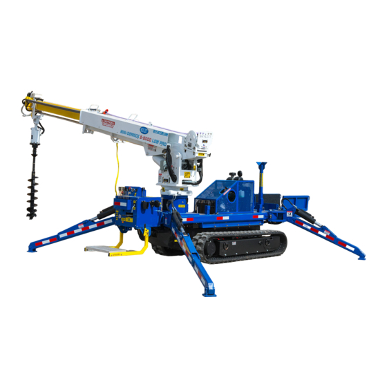
- Page 1 Mini-Derrick Super 6000 Low Pro Parts and Maintenance Manual Skylift Inc. 3000 Leavitt Road Unit 6 Lorain, Ohio 44052 440-960-2100 info@skyliftus.com...
- Page 2 It is assumed that the personnel possessing this document has the knowledge and background to use the Skylift Mini-Derrick Super 6000 LP. It is your responsibility to read and understand this manual before operating the Skylift Mini-Derrick Super 6000 LP.
- Page 3 No associate, agent or representative of Skylift is authorized to extend any warranty on Skylift’s behalf. Skylift shall in no event be liable for any special, indirect, or consequential damages or claims of any third party against the Customer.
- Page 4 In order to insure the correct processing of any warranty claim, it is important that this page be filled out and returned to SKYLIFT, INC. at the address given below within ten (10) days of the delivery date of the equipment.
- Page 5 The Skylift technician will estimate labor hours for the repair as well. Skylift MUST provide the parts for the repair if there are any parts that need to be replaced on the equipment.
- Page 6 Warranty Guidelines / Instructions WARRANTY CLAIM FORM Skylift, Inc. 3000 Leavitt Rd., Unit 6 Skylift Warranty Department Lorain, OH 44052 FAX: (440) 960-2104 susan@skyliftus.com Today’s Date: __________ Claim, Repair, or Work Order No. ____________ Skylift Model Type Unit Serial No.
- Page 7 Pin Retainers bolted Tie Down Hooks Make sure bolts are tight Wheel Lug Nuts If equipped: Make sure bolts are tight These inspection intervals are recommended by Skylift Inc. If there are further maintenance questions, contact Skylift Inc. at 440-960-2100...
- Page 8 Load Chart - Overhead...
- Page 9 Load Chart – Can Handler...
- Page 10 Load Chart – Material Handler...
-
Page 11: Table Of Contents
DWG. NO. PROPRIETARY AND CONFIDENTIAL THE INFORMATION CONTAINED IN THIS DRAWING IS THE SOLE PROPERTY OF FINISH SKYLIFT. ANY REPRODUCTION IN PART OR AS A WHOLE WITHOUT THE WRITTEN SCALE: WEIGHT: PERMISSION OF SKYLIFT IS PROHIBITED. DO NOT SCALE DRAWING... - Page 12 SIZE DWG. NO. PROPRIETARY AND CONFIDENTIAL THE INFORMATION CONTAINED IN THIS DRAWING IS THE SOLE PROPERTY OF FINISH SKYLIFT. ANY REPRODUCTION IN PART OR AS A WHOLE WITHOUT THE WRITTEN SCALE: WEIGHT: SHEET PERMISSION OF SKYLIFT IS PROHIBITED. DO NOT SCALE DRAWING...
- Page 13 DWG. NO. MATERIAL PROPRIETARY AND CONFIDENTIAL THE INFORMATION CONTAINED IN THIS FINISH DRAWING IS THE SOLE PROPERTY OF SKYLIFT. ANY REPRODUCTION IN PART OR AS A WHOLE WITHOUT THE WRITTEN SCALE: WEIGHT: PERMISSION OF SKYLIFT IS PROHIBITED. DO NOT SCALE DRAWING...
- Page 14 REAR OUTRIGGER SOCKET, MIDDLE THE INFORMATION CONTAINED IN THIS FINISH DRAWING IS THE SOLE PROPERTY OF ROTATION GEAR SKYLIFT. ANY REPRODUCTION IN PART OR AS A WHOLE WITHOUT THE WRITTEN LIFT CYLILINDER TURRET PIVOT SCALE: 1:64 WEIGHT: PERMISSION OF SKYLIFT IS PROHIBITED.
- Page 15 MATERIAL PROPRIETARY AND CONFIDENTIAL THE INFORMATION CONTAINED IN THIS FINISH DRAWING IS THE SOLE PROPERTY OF SKYLIFT. ANY REPRODUCTION IN PART OR AS A WHOLE WITHOUT THE WRITTEN SCALE: 1:64 WEIGHT: SHEET 5 OF 6 PERMISSION OF SKYLIFT IS PROHIBITED.
- Page 16 MATERIAL PROPRIETARY AND CONFIDENTIAL THE INFORMATION CONTAINED IN THIS FINISH DRAWING IS THE SOLE PROPERTY OF SKYLIFT. ANY REPRODUCTION IN PART OR AS A WHOLE WITHOUT THE WRITTEN SCALE: 1:64 WEIGHT: SHEET 6 OF 6 PERMISSION OF SKYLIFT IS PROHIBITED.
- Page 17 THE INFORMATION CONTAINED IN THIS FINISH DRAWING IS THE SOLE PROPERTY OF ALL TANK LINES RETURN TO TANK THRU FILTER SET @ 3000 PSI SKYLIFT. ANY REPRODUCTION IN PART OR AS A WHOLE WITHOUT THE WRITTEN SCALE: 1:1 WEIGHT: SHEET 1 OF 1 PERMISSION OF SKYLIFT IS PROHIBITED.
- Page 18 SLOPE IGNITION INDICATOR ALARM SWITCH POWER PINK BATTERY RELAY MDL 15 FUSE WIRED 10 GA WHITE 12 VDC RITE AUGER STOW ALTERNATOR INTERLOCK SWITCH OVERRIDE SENSOR LOOM OUTRIGGER WARNING SWITCHES OUTRIGGER INTERLOCK LIGHT SOLENOID VALVE BOOM STOW PROX SENSORS SWITCH LIGHT SWITCH FUEL...
- Page 19 USED W/ LOFA THE INFORMATION CONTAINED IN THIS FINISH CONTROLS DRAWING IS THE SOLE PROPERTY OF SKYLIFT. ANY REPRODUCTION IN PART OR AS A WHOLE WITHOUT THE WRITTEN SCALE: 1:1 WEIGHT: SHEET 1 OF 2 PERMISSION OF SKYLIFT IS PROHIBITED.
- Page 20 USED W/ LOFA THE INFORMATION CONTAINED IN THIS FINISH CONTROLS DRAWING IS THE SOLE PROPERTY OF SKYLIFT. ANY REPRODUCTION IN PART OR AS A WHOLE WITHOUT THE WRITTEN SCALE: 1:1 WEIGHT: SHEET 2 OF 2 PERMISSION OF SKYLIFT IS PROHIBITED.
- Page 21 EL240 Series Panel Schematic with Delphi GT Connector Key Switch Electrical Diagram Position 12 V Max 24 V Max 30-58 30-15/54 35 A 17.5 A J8-H1 J16-H1 30-19 70 A 30 A 30-17 70 A 30 A 70 A 40 A 30-50a 18 A J23-H1...
- Page 22 CHAPTER 1: Fuel Tank...
- Page 23 PROPRIETARY AND CONFIDENTIAL 3485 THE INFORMATION CONTAINED IN THIS FINISH DRAWING IS THE SOLE PROPERTY OF BLUE SKYLIFT. ANY REPRODUCTION IN PART OR AS A WHOLE WITHOUT THE WRITTEN SCALE: WEIGHT: SHEET 2 OF 2 PERMISSION OF SKYLIFT IS PROHIBITED.
- Page 24 Chapter 2: Hydraulic Tank...
-
Page 25: Tier 4 Above Slab Hydraulic Tank
PROPRIETARY AND CONFIDENTIAL 4160 THE INFORMATION CONTAINED IN THIS FINISH DRAWING IS THE SOLE PROPERTY OF BLUE SKYLIFT. ANY REPRODUCTION IN PART OR AS A WHOLE WITHOUT THE WRITTEN SCALE: WEIGHT: SHEET 6 OF 6 PERMISSION OF SKYLIFT IS PROHIBITED. - Page 26 DWG. NO. MATERIAL PROPRIETARY AND CONFIDENTIAL THE INFORMATION CONTAINED IN THIS FINISH DRAWING IS THE SOLE PROPERTY OF SKYLIFT. ANY REPRODUCTION IN PART OR AS A WHOLE WITHOUT THE WRITTEN SCALE: WEIGHT: SHEET 1 OF 1 PERMISSION OF SKYLIFT IS PROHIBITED.
- Page 27 Chapter 3: Boom Assembly...
-
Page 28: Complete Boom Assembly
PROPRIETARY AND CONFIDENTIAL THE INFORMATION CONTAINED IN THIS 4250 DRAWING IS THE SOLE PROPERTY OF FINISH SKYLIFT. ANY REPRODUCTION IN PART OR AS A WHOLE WITHOUT THE WRITTEN SCALE: 1:24 WEIGHT: SHEET 1 OF 1 PERMISSION OF SKYLIFT IS PROHIBITED. - Page 29 The Most Common Maintenance Issues With Fiberglass Booms 1. Not keeping the boom clean inside and out A dirty boom does not shed rain as well and can fail periodic dielectric tests. 2. Cleaning with harsh abrasive cleaners Abrasives and solvent cleaners are not recommended as they can scratch or soften the surface cleaners coatings.
- Page 30 9. Sunshine and ultraviolet radiation Sunlight and UV can attack an unpainted area of a fiberglass boom causing the exposed area to look fuzzy as the fibers are exposed. Repair surface scratches, to seal out the sun and moisture, to prevent this problem.
- Page 31 Warranty Policy This warranty is issued to the original purchaser only and applies only to booms, which have been used for their intended purpose, within designed capacities, and not subjected to abuse, misuse and/or improper maintenance. We will repair or replace booms at our discretion, found upon our inspection at Waco Boom Company Ltd, to be defective in material or our workmanship for up to one year from the date of placement into service or 18 months from date of shipment from Waco Boom Company Ltd., whichever comes first.
-
Page 32: Turret Assembly
Chapter 4: Turret Assembly... - Page 33 PROPRIETARY AND CONFIDENTIAL 4251 THE INFORMATION CONTAINED IN THIS FINISH DRAWING IS THE SOLE PROPERTY OF SKYLIFT. ANY REPRODUCTION IN PART OR AS A WHOLE WITHOUT THE WRITTEN SCALE: 1:16 WEIGHT: SHEET 1 OF 1 PERMISSION OF SKYLIFT IS PROHIBITED.
- Page 34 Installation and Operating Manual Slew Drives WD-L, WD-H, SP-L, SP-I, SP-M, SP-H IO SD 1.00 Read the operating manual prior to starting all work!
- Page 35 Slew Drives Installation and commissioning 5 Installation and commissioning 5.1 Safety Prior to starting work switch off all energy supplies and DANGER DANGER DANGER DANGER safeguard them from being switched on again. If the power supply is switched on by unauthorized personnel, a life-threatening danger exists for persons in the danger zone.
- Page 36 Slew Drives Installation and commissioning Personal protective equipment Wear the following protective equipment for all installation and commissioning work: Protective work clothing Safety footwear Protective gloves The warnings in this chapter make special reference to additional protective equipment that is required for certain tasks.
- Page 37 Slew Drives Installation and commissioning When using cleaning agents, ensure adequate ventilation. Maintain a strict ban on smoking. Remove old grease, dust, and fouling with lint-free cloths. Remove foreign material from the support surface of the mounting structure (including paint residue, welding beads, burrs).
- Page 38 Slew Drives Installation and commissioning δp = flatness deviation max. δp = maximum flatness deviation U = circumference The maximum residual value for flatness deviation δp in the circumferential direction should only be reached once on half of the circumference. The gradient must look like a sinus curve that slowly rises or falls.
- Page 39 Slew Drives Installation and commissioning Permissible flatness and perpendicularity deviation for series WD-L and SP slew drives Running circle diameter [mm] ≥100 ≥250 ≥500 ≥750 ≥1000 ≥1250 Permissible flatness deviation [mm] 0.04 0.06 0.08 0.09 0.10 0.11 including perpendicularity [in] 0.0016 0.0024 0.0032...
- Page 40 Slew Drives Installation and commissioning Axial deflection, tilting, radial extension (or radial IMPORTANT contraction) of the mounting structure under max. load causes deformation of the mounting structure. 5.2.4 Selecting the mounting elements Only use mounting elements of the correct size, number CAUTION CAUTION CAUTION...
- Page 41 Slew Drives Installation and commissioning 5.2.5 Tightening bolts with a torque wrench Normally the mounting bolts are adequately secured through correct pretension. Do not use impact screwdrivers. Using an impact WARNI WARNI WARNI WARNING screwdriver may cause impermissible deviations between the bolt tightening forces.
- Page 42 Slew Drives Installation and commissioning Tightening torques and bolt tightening forces for inch thread in accordance with ANSI B1.1 when using a torque wrench: Mounting bolt Tightening torque Mounting dimensions pretension force Strength class Strength class Grade 8 Grade 8 ft-lbs 0.1900 –...
- Page 43 Slew Drives Installation and commissioning The prescribed hydraulic pressure should not be exceeded WARNI WARNI WARNI WARNING when pretensioning the bolts. Excess hydraulic pressure may cause failure of the bolted union with the mounting structure and may cause severe personal injury or material damage.
- Page 44 Slew Drives Installation and commissioning 2 – 4.5 UNC 1239 278538 2 1/4 – 4.5 UNC 1608 361493 2 1/2 – 4 UNC 1981 445347 2 3/4 – 4 UNC 2442 548984 Tab. 11 for hydraulic bolt-tensioning cylinder pretensioned to 85% of yield strength 5.3 Installing the slew drive 5.3.1 Hardness gap...
- Page 45 Slew Drives Installation and commissioning 2. Arrange the hardness gap ( section 5.3.1 "Hardness gap") of the bearing ring charged with point load so that it is offset by 90° relative to the main load-carrying zone. The main load- carrying zone is in the main slewing range. CAUTION! The hardness gap or the filling plug in a slewing CAUTION! CAUTION!
- Page 46 Slew Drives Installation and commissioning The end customer or the operating company must be instructed which tightening process was used. The process must also be used when servicing the unit to check the bolted union. Tightening torque M in Nm with incremental tightening Step 1 Step 2 Step 3...
- Page 47 Slew Drives Installation and commissioning Tightening torque M in ft-lbs with incremental tightening Step 1 Step 2 Step 3 100% Mounting bolt dimensions Tightening torque M in ft-lbs Strength class 10.9 2.50 6.80 8.50 6.20 16.5 20.7 12.3 33.0 41.2 21.6 57.6 72.0...
- Page 48 Slew Drives Installation and commissioning Dial gauge Upper mounting structure Slew Drive Lower mounting structure Fig. 24: Measurement setup Procedure: Tilting clearance measurement 1. Switch off the system and safeguard it from being turned on again. 2. Permanently mark the measuring point in the main load direction on the housing and on the bearing ring.
- Page 49 Slew Drives Installation and commissioning 3. Remove the drive with the goal of ensuring that the worm shaft can be freely and easily moved by hand. If using a front-end brake (flanged-mounted between motor and slew drive): Remove front-end brake and motor ( Operating manual for the front-end brake and motor).
- Page 50 Slew Drives Maintenance 6 Maintenance Follow the instructions provided in the operating manuals for the drive motors (hydraulic or electric), as well as the instructions provided for the optional potentiometer or permanent brake. 6.1 Safety Prior to starting work switch off all energy supplies and DANGER DANGER DANGER...
- Page 51 Slew Drives Maintenance 6.2 Cleaning Use cold solvent (e.g. white spirit, diesel oil, Kaltryl KEV) IMPORTANT that does not corrode the sealing material. Ensure that the cleaning agent does not get into the slew drive. Do not use a high-pressure cleaner to clean the slew drive. Unsuitable trichloroethylene-based or perchloroethylene-based cleaning agents, or other extremely aggressive cleaners damage the seal and may cause bearing damage.
- Page 52 Slew Drives Maintenance wö Interval Maintenance task To be executed by weekly Check seal Specialist after 100 operating Tighten bolts Specialist hours Check tilting clearance Specialist after every additional Tighten bolts Specialist 700 operating hours Reduce the inspection interval if there is heavy wear or at least every 6 or continuous operation.
- Page 53 Slew Drives Maintenance The specified values are valid for the following conditions: Operating temperature on the slew drive < 70° C (158° F). Circumferential speed < 0.5 m/s (1.64 ft/sec) for SP slew drives. Output speed < 5 rpm for WD slew drives. Low to moderate load.
- Page 54 Slew Drives Maintenance Checking the tilting clearance increase d directly on the slew drive The measured value m1 determined at installation serves as the base value ( section 5.3.4 "Determination of tilting clearance"). Determine the value mx as described in the section 5.3.4 "Determining the tilting clearance".
- Page 55 Slew Drives Maintenance 6.4.4 Lubricating the slew drive Regularly lubricate the slew drives to prolong their service IMPORTANT life and ensure safe operation. Always use the lubricants specified in the order drawing. If IMPORTANT using other lubricants pay attention to the relative mixability of the substances.
- Page 56 Hydraulic Overload Protection Calibration Procedure (Electric Version) SUPER 5000, SUPER 6000, & PATRIOT 40/50 units only! Requirements for test: 2,000 lbs. plus 200 lbs. is required for this procedure. STEP 1. Set main control valve pressure to 3,000 PSI at full throttle. ...
- Page 58 Chapter 5: Auger Assembly...
-
Page 59: Auger Drive Assembly
PROPRIETARY AND CONFIDENTIAL 4252 THE INFORMATION CONTAINED IN THIS FINISH DRAWING IS THE SOLE PROPERTY OF SKYLIFT. ANY REPRODUCTION IN PART OR AS A WHOLE WITHOUT THE WRITTEN SCALE: 1:24 WEIGHT: SHEET 1 OF 2 PERMISSION OF SKYLIFT IS PROHIBITED. - Page 60 PROPRIETARY AND CONFIDENTIAL 2261 THE INFORMATION CONTAINED IN THIS 35°F FINISH DRAWING IS THE SOLE PROPERTY OF SKYLIFT. ANY REPRODUCTION IN PART OR 31oz Oil Capacity AS A WHOLE WITHOUT THE WRITTEN SCALE: WEIGHT: SHEET 2 OF 2 PERMISSION OF SKYLIFT IS PROHIBITED.
-
Page 61: Valve Frame Assembly
Chapter 6: Valve Frame Assembly... - Page 62 PROPRIETARY AND CONFIDENTIAL THE INFORMATION CONTAINED IN THIS 4253 DRAWING IS THE SOLE PROPERTY OF FINISH SKYLIFT. ANY REPRODUCTION IN PART OR AS A WHOLE WITHOUT THE WRITTEN SCALE: 1:8 WEIGHT: SHEET 1 OF 2 PERMISSION OF SKYLIFT IS PROHIBITED.
- Page 63 PROPRIETARY AND CONFIDENTIAL 4255 THE INFORMATION CONTAINED IN THIS FINISH DRAWING IS THE SOLE PROPERTY OF SKYLIFT. ANY REPRODUCTION IN PART OR AS A WHOLE WITHOUT THE WRITTEN SCALE: 1:4 WEIGHT: SHEET 1 OF 1 PERMISSION OF SKYLIFT IS PROHIBITED.
- Page 64 PROPRIETARY AND CONFIDENTIAL ELE-115 THE INFORMATION CONTAINED IN THIS FINISH DRAWING IS THE SOLE PROPERTY OF SKYLIFT. ANY REPRODUCTION IN PART OR AS A WHOLE WITHOUT THE WRITTEN SCALE: 1:1 WEIGHT: SHEET 1 OF 1 PERMISSION OF SKYLIFT IS PROHIBITED.
- Page 65 Professional radio remote controls Installation and Quick Start Guide G2B Radio Remote Control System System Name Manual Part Number Revision Date Skylift Mini-Derrick Super 6000 Rev.8 110-002-0001-01-00 Rev.0 11/15/18 Installation and Quick Start Guide 110-002-0001-01-00...
- Page 66 Table of Contents G2B System Overview …………………………………………………………………………………………………………… CU Installation and Wiring …………………………………………………………………………………………………………… Locating the CU ………………………………………………………………………………. Grease Contacts ……………………………………………………………………………... Feed Cable ……………………………………………………………………………… Secure Cable ……………………………………………………………………………… Terminal Schematic ……………………………………………………………………………… Special Logic Functions ……………………………………………………………………………… Wire I/O ……………………………………………………………………………… CU (Receiver) Overview …………………………………………………………………………………………………………… CU Layout and Indicators ………………………………………………………………………………………….
-
Page 67: G2B System Overview
G2B System Overview This guide is intended as a complement to the Service Manual and Remote Control System RC400 G2 Instruction manual. It is a brief overview of the important features of a specific radio remote control system. Installers and Op- erators must read the Service Manual and Instruction manual before installing / operating the system and adhere to all warnings and recommendations. -
Page 68: Cu Installation And Wiring
CU Installation and Wiring The following instructions will help an installer wire the Central Unit to the controls of your specific machine. The in- staller may choose to make the wiring harness himself or use the generic Scanreco wiring harnesses for ease of in- stallation. -
Page 69: Terminal Schematic
E. Terminal Schematic Main Pin no Function K7.1 Supply (+12/24VDC) K1 Analog 1-4 K7.2 Ground (GND) K7.3 Dump Valve Out (DV+) K4 EX1 K3 Analog 5-8 K7.4 DV GND K6 EX2 Note: An electrically controlled dump valve should always be connected, for safety reasons, between the function valves and the hydraulic tank. -
Page 70: Special Logic Functions
F. Special Logic Functions All travel functions on paddles will only activate while the “Travel” switch is ON. All boom functions on paddles will only activate while one of the “Boom Enable” switches is ON. Pole Claw Tilt will only activate while one of the “Boom Enable” switches is ON. Engine Start will only activate while the “Boom Enable”... -
Page 71: Cu (Receiver) Overview
CU (Receiver) 3.1 CU Layout and Indicators The Central Unit is equipped with 2 individual positions where status and operational indications can be read, the external LED’s: DV and STATUS provide basic information. The internal LED display provides more detailed infor- mation. -
Page 72: Dv And Status Led's
3.5 DV and STATUS LED’s Operational status indications can be read from the DV and STATUS LED’s as follows: Status LED Description DV LED Description (Dump Valve) CU is OFF or not powered Dump Valve Output is OFF CU is ON with no link to PCU Dump Valve Output is ON GREEN CU is ON and linked with PCU (via cable... -
Page 73: Error Indicators
3.6.2 Error Indicators The Central Unit will indicate detected errors via the internal double 7-segment LED display. If the Central Unit de- tects an error it will be indicated by the STATUS LED flashing red; while the Internal LED Display indicates the error code. - Page 74 3.6.2 Error Indicators (cont’d…) Block 2 Block 3 Description Cause Action Illegal voltage Wrong current on analog output System will self reset. Check connec- Analog output (Block 3 declares related output; tions. Remove terminal connector and 1A,1B….). reset system. CAN Passive CAN bus in passive mode.
-
Page 75: Pcu (Transmitter) Overview
4.1 Mini Switch and Paddle Layout Switch Legend Latched or Detent Momentary or Spring return Locking—Lift to operate Uni-Directional Potentiometer (0-10) UNI-POT BI-POT Bi-Directional Potentiometer (10-0-10) AXIS Paddles Position Function in UP (A) Direction Function in DOWN (B) Direction DOWN/CLOSE UP/OPEN AUGER/WINCH DOWN AUGER/WINCH UP... -
Page 76: Power / Stop / Micro Switch Panel
4.2 Power / Stop / Micro Speed Switch Panel Description Micro Speed (Green) / RF Indicator (Red) LED Power ON / Low Battery LED Micro Speed Switch Stop Function Mushroom Button; twist to reset Power / Function Button The above figure and table detail the layout of a Maxi generic Power / Stop / Micro Speed Switch panel. Mini switch panels are very similar in layout with the same functionality. -
Page 77: Powering The Pcu
4.4 Powering the PCU Install charged battery or connect tether cable Rotate E-Stop CW Press and hold Power Button until Power ON LED will illuminates solid RED Note: If no link is established the RF indicator LED will flash RED 4 times then turn off. Continue to Section 4.6 Downloading ID: Pairing PCU and CU. -
Page 78: Downloading Id: Pairing Pcu And Cu
4.6 Downloading ID: Pairing PCU and CU Programs the unique ID-code required for radio communication between the Portable Control Unit and Central Unit. Typically the CU may store a maximum of 1 PCU ID-code. If another PCU is required to operate the CU via radio, the ID-code procedure is re- quired to be done and the previous ID-code will be overwritten. - Page 79 SLOPE GAUGE CALIBRATION GUIDE Skylift, Inc. 3000 Leavitt Road Unit 6 Lorain, Ohio 44052 Office:440-960-2100 Fax: 440-960-2104 www.Skyliftus.com...
- Page 80 Calibration The calibration setting is located on the 4 page of the settings menu. After the MPIC-Slope has been installed, one of the first things that should be done is to calibrate the module for its installation. When calibrating the module, it should be at a level position that is considered a slope of 0, and it should not be in motion or have any vibration.
- Page 81 Warning: If the MPIC-Slope is not completely still for a calibration, the calibrated value can be off which can result in non-desired slope readings. The module should not be in motion and should not be vibrating. If further assistance is required contact Skylift.
-
Page 82: Slab Assembly
Chapter 7: Slab Assembly... - Page 83 PROPRIETARY AND CONFIDENTIAL 4254 THE INFORMATION CONTAINED IN THIS FINISH DRAWING IS THE SOLE PROPERTY OF POLE CARRIER SKYLIFT. ANY REPRODUCTION IN PART OR MEC-531 AS A WHOLE WITHOUT THE WRITTEN RATCHET & STRAP SCALE: 1:48 WEIGHT: SHEET 1 OF 1 PERMISSION OF SKYLIFT IS PROHIBITED.
- Page 84 PROPRIETARY AND CONFIDENTIAL 3745-1 800-351600 OUTRIGGER CYLINDER THE INFORMATION CONTAINED IN THIS FINISH DRAWING IS THE SOLE PROPERTY OF SKYLIFT. ANY REPRODUCTION IN PART OR PIN-125 DROP PIN AS A WHOLE WITHOUT THE WRITTEN SCALE: 1:12 WEIGHT: SHEET 1 OF 1 PERMISSION OF SKYLIFT IS PROHIBITED.
- Page 85 PROPRIETARY AND CONFIDENTIAL 3745-2 THE INFORMATION CONTAINED IN THIS FINISH DRAWING IS THE SOLE PROPERTY OF SKYLIFT. ANY REPRODUCTION IN PART OR AS A WHOLE WITHOUT THE WRITTEN SCALE: 1:12 WEIGHT: SHEET 1 OF 1 PERMISSION OF SKYLIFT IS PROHIBITED.
- Page 86 PROPRIETARY AND CONFIDENTIAL 3745-3 THE INFORMATION CONTAINED IN THIS FINISH DRAWING IS THE SOLE PROPERTY OF SKYLIFT. ANY REPRODUCTION IN PART OR AS A WHOLE WITHOUT THE WRITTEN SCALE: 1:12 WEIGHT: SHEET 1 OF 1 PERMISSION OF SKYLIFT IS PROHIBITED.
- Page 87 PROPRIETARY AND CONFIDENTIAL 3745-4 PIN-125 DROP PIN THE INFORMATION CONTAINED IN THIS FINISH DRAWING IS THE SOLE PROPERTY OF SKYLIFT. ANY REPRODUCTION IN PART OR 800-351600 OUTRIGGER CYLINDER AS A WHOLE WITHOUT THE WRITTEN SCALE: 1:12 WEIGHT: SHEET 1 OF 1 PERMISSION OF SKYLIFT IS PROHIBITED.
- Page 88 Chapter 8: Track Undercarriage...
- Page 89 Table of Contents SAFETY PRECAUTIONS TECHNICAL INFORMATION MAINTENANCE BILL OF MATERIALS...
- Page 90 SAFETY PRECAUTIONS A brief definition of signal words that may be used in this manual: ! DANGER Indicates an imminently hazardous situation that, if not avoided, will result in serious injury or death. ! WARNING Indicates a potentially hazardous situation that, if not avoided, could result in death or serious injury, and includes hazards that are exposed when guards are removed.
- Page 91 FOR YOUR SAFETY: Always wear eye protection when operating or servicing the unit. • Do not depend on hydraulic pressure applied to blades or backhoe to elevate • machine for track unit service. Always service track units and undercarriage from outside or from above the unit rather than from underneath. Escaping hydraulic fluid under pressure can penetrate the skin and cause serious •...
- Page 92 TECHNICAL INFORMATION TRACK MAINTENANCE Due to functional necessity the components of the undercarriage are open to soil, sand, rock, water, chemicals and the elements. Regular maintenance of the undercarriage is inevitable throughout the course of normal machine use. PRECAUTIONS/HANDLING RECOMMENDATIONS Installation and Repair Only trained personnel should perform the mounting of rubber tracks.
- Page 93 drive and support rollers. Mud buildup on rollers increases track tension; therefore, very regular cleanup is required under this condition. Operating Tips Ideal operation is to keep both tracks equally loaded and both tracks fully and evenly supported by the ground. Since this is not always practical, manage the deviations wisely to conform as closely as possible to ideal conditions.
- Page 94 Drive slowly and carefully to avoid unfavorable terrain and obstacles that could damage the track. It is recommended to make multiple large radius turns instead of making single, sharp turns. Make “Y” turns to change direction. Avoid slipping and spinning the tracks. Drive carefully on rough terrain and gravel surfaces.
- Page 95 STORAGE If rubber tracks are stored for long periods of time, they should be kept indoors to avoid exposure to direct sunlight and weather conditions to avoid deterioration. Tracks should be stored on their side. Do not lay flat (as if it were on a machine) unless support has been provided to the inside of the track.
- Page 96 MAINTENANCE ! WARNING Never attempt to clean, adjust or lubricate a track unit while it is in motion. Failure to heed may result in serious personal injury or death. GENERAL Proper tension of the rubber track is essential for maximum track and undercarriage life and will result in less down time.
- Page 97 ADJUSTMENTS Inspect Tension Check the tension at the tensioner viewport to ensure the engraved tensioner ring is in the correct position. The engraved tensioner ring should be flush with the tensioner mount plate. If the engraved tensioner ring is not in the correct location, you must adjust tension to prevent damage to the tracks.
- Page 98 Adjust Tension 1. Remove the protective plug that covers the grease relief valve. 2. Support track assembly so the track clears the ground. 3. Apply a standard grease gun to the grease valve fitting (zerk) and slowly pump grease to extend the track tensioner against the compression spring. 4.
- Page 99 7790 - COMPLETE 90” TRACK ASSEMBLY Default/ ITEM NO. PART NUMBER DESCRIPTION QTY. 7750 CENTER TRACK ASSEMBLY 7720 RIGHT TRACK ASSEMBLY 7700 LEFT TRACK ASSEMBLY 7725 EXTEND/RETRACT ASSEMBLY CENTER TRACK ASSEMBLY SKID 7751 PLATE BOLT 5/8-11 UNC BOLT 7773 AGGRESSIVE RUBBER TRACK 7772 EXTENSION CYLINDER...
- Page 100 7700- 90” LEFT TRACK ASSEMBLY ITEM NO. PART NUMBER DESCRIPTION QTY. 7701 LEFT PLATE 7702 OUTSIDE LEFT PLATE 7703 LEFT OUTER PLATE 7704 TRACK GUIDE 7705 GEAR MOUNT PLATE 7706 GUSSET (1) 7707 DRIVE MOTOR MOUNT PLATE 7774 DRIVE MOTOR 7708 GUSSET (2) 7721...
- Page 101 7720- 90” RIGHT TRACK ASSEMBLY ITEM NO. PART NUMBER DESCRIPTION QTY. 7761 TENSIONER MOUNT PLATE GUSSET 7708 GUSSET (2) 7778 IDLER BOGIE 7774 DRIVE MOTOR 7721 2.5X3.5X6.75 SUPPORT TUBING 7723 1X1X13" TENSIONER GUIDE 7722 1X1X9" TENSIONER GUIDE 7724 TENSIONER SUPPORT L ANGLE 5/8"-11 UNC BOLT 5/8"-11 UNC NUT 7759...
- Page 102 7750- 90” CENTER TRACK ASSEMBLY ITEM NO. PART NUMBER DESCRIPTION QTY. 7731 HYDRAULIC TANK 7732 REAR HYDRAULIC TANK CAP 7733 FRONT HYDRAULIC TANK CAP 7734 SLAB MOUNT PLATE 7735 SKID PLATE STANDOFF 7736 4X5X.25 TUBING 7737 4X5X.25 TUBING BRACE HYDRAULIC EXTEND/RETRACT 7738 CYLINDER MOUNT (1) HYDRAULIC EXTEND/RETRACT...
- Page 103 90” TRACK SUCTION ASSEMBLY ITEM PART DESCRIPTION QTY. 7771 SUCTION LINE 7768 SUCTION FILTER CLAMP 1.75" T BOLT CLAMP BARB 1.25" NPT BARB FITTING ELBOW 1.25" NPT 90° ELBOW 1.25" NPT 4" LONG NIPPLE NIPPLE...
- Page 104 90” TRACK TENSIONER ASSEMBLY ITEM PART DESCRIPTION QTY. NUMBER 7763 MALE TENSIONER ASSY 7757 TENSIONER MOUNT PLATE 7758 COUNTERSUNK RETAINER PLATE COUNTERSUNK 5/8-11 UNC BOLT 7766 90" TRACK TENSIONER SPRING 7756 TRACK TENSIONER CYLINDER BODY 7767 13 INCH IDLER WHEEL W/ SLIDE BARS SOCKET CAP M10X35 BOLT 7764 1.50 INCH U SEAL...
- Page 105 THE INFORMATION CONTAINED IN THIS FINISH DRAWING IS THE SOLE PROPERTY OF LEVEL CHECK PORT PLUG 9-13 FT-LB SKYLIFT. ANY REPRODUCTION IN PART OR AS A WHOLE WITHOUT THE WRITTEN SCALE: WEIGHT: SHEET 1 OF 1 PERMISSION OF SKYLIFT IS PROHIBITED.
- Page 106 Chapter 9: Engine...
- Page 107 MATERIAL PROPRIETARY AND CONFIDENTIAL ENG-700 THE INFORMATION CONTAINED IN THIS FINISH DRAWING IS THE SOLE PROPERTY OF SKYLIFT. ANY REPRODUCTION IN PART OR AS A WHOLE WITHOUT THE WRITTEN SCALE: WEIGHT: SHEET 1 OF 1 PERMISSION OF SKYLIFT IS PROHIBITED.
- Page 108 Chapter 10: Accessories...
- Page 109 MATERIAL PROPRIETARY AND CONFIDENTIAL 3000 THE INFORMATION CONTAINED IN THIS FINISH DRAWING IS THE SOLE PROPERTY OF SKYLIFT. ANY REPRODUCTION IN PART OR AS A WHOLE WITHOUT THE WRITTEN SCALE: WEIGHT: SHEET 1 OF 1 PERMISSION OF SKYLIFT IS PROHIBITED.
- Page 110 DWG. NO. MATERIAL PROPRIETARY AND CONFIDENTIAL THE INFORMATION CONTAINED IN THIS FINISH DRAWING IS THE SOLE PROPERTY OF SKYLIFT. ANY REPRODUCTION IN PART OR AS A WHOLE WITHOUT THE WRITTEN SCALE: WEIGHT: SHEET 1 OF 1 PERMISSION OF SKYLIFT IS PROHIBITED.
- Page 111 MATERIAL PROPRIETARY AND CONFIDENTIAL THE INFORMATION CONTAINED IN THIS 3088 FINISH DRAWING IS THE SOLE PROPERTY OF SKYLIFT. ANY REPRODUCTION IN PART OR AS A WHOLE WITHOUT THE WRITTEN SCALE: WEIGHT: SHEET 1 OF 1 PERMISSION OF SKYLIFT IS PROHIBITED.
- Page 112 MATERIAL PROPRIETARY AND CONFIDENTIAL THE INFORMATION CONTAINED IN THIS FINISH DRAWING IS THE SOLE PROPERTY OF SKYLIFT. ANY REPRODUCTION IN PART OR AS A WHOLE WITHOUT THE WRITTEN SCALE: 1:12 WEIGHT: SHEET 1 OF 1 PERMISSION OF SKYLIFT IS PROHIBITED.
- Page 113 MATERIAL PROPRIETARY AND CONFIDENTIAL 3740 THE INFORMATION CONTAINED IN THIS FINISH DRAWING IS THE SOLE PROPERTY OF SKYLIFT. ANY REPRODUCTION IN PART OR AS A WHOLE WITHOUT THE WRITTEN SCALE: WEIGHT: SHEET 2 OF 3 PERMISSION OF SKYLIFT IS PROHIBITED.
- Page 114 PROPRIETARY AND CONFIDENTIAL Complete THE INFORMATION CONTAINED IN THIS FINISH DRAWING IS THE SOLE PROPERTY OF Bucket SKYLIFT. ANY REPRODUCTION IN PART OR Assembly AS A WHOLE WITHOUT THE WRITTEN SCALE: 1:24 WEIGHT: SHEET 1 OF 1 PERMISSION OF SKYLIFT IS PROHIBITED.
- Page 115 PROPRIETARY AND CONFIDENTIAL 5700 THE INFORMATION CONTAINED IN THIS FINISH DRAWING IS THE SOLE PROPERTY OF SKYLIFT. ANY REPRODUCTION IN PART OR AS A WHOLE WITHOUT THE WRITTEN SCALE: 1:8 WEIGHT: SHEET 2 OF 2 PERMISSION OF SKYLIFT IS PROHIBITED.
- Page 116 DWG. NO. MATERIAL PROPRIETARY AND CONFIDENTIAL THE INFORMATION CONTAINED IN THIS FINISH DRAWING IS THE SOLE PROPERTY OF SKYLIFT. ANY REPRODUCTION IN PART OR AS A WHOLE WITHOUT THE WRITTEN SCALE: WEIGHT: SHEET 1 OF 1 PERMISSION OF SKYLIFT IS PROHIBITED.
- Page 117 DWG. NO. MATERIAL PROPRIETARY AND CONFIDENTIAL THE INFORMATION CONTAINED IN THIS FINISH DRAWING IS THE SOLE PROPERTY OF SKYLIFT. ANY REPRODUCTION IN PART OR AS A WHOLE WITHOUT THE WRITTEN SCALE: WEIGHT: SHEET 1 OF 1 PERMISSION OF SKYLIFT IS PROHIBITED.
- Page 118 MATERIAL PROPRIETARY AND CONFIDENTIAL 2450A THE INFORMATION CONTAINED IN THIS FINISH DRAWING IS THE SOLE PROPERTY OF SKYLIFT. ANY REPRODUCTION IN PART OR AS A WHOLE WITHOUT THE WRITTEN SCALE: WEIGHT: SHEET 2 OF 2 PERMISSION OF SKYLIFT IS PROHIBITED.
- Page 119 MATERIAL PROPRIETARY AND CONFIDENTIAL 3592A THE INFORMATION CONTAINED IN THIS FINISH DRAWING IS THE SOLE PROPERTY OF SKYLIFT. ANY REPRODUCTION IN PART OR AS A WHOLE WITHOUT THE WRITTEN SCALE: WEIGHT: SHEET 2 OF 2 PERMISSION OF SKYLIFT IS PROHIBITED.
- Page 120 DWG. NO. MATERIAL PROPRIETARY AND CONFIDENTIAL THE INFORMATION CONTAINED IN THIS FINISH DRAWING IS THE SOLE PROPERTY OF SKYLIFT. ANY REPRODUCTION IN PART OR AS A WHOLE WITHOUT THE WRITTEN SCALE: WEIGHT: SHEET 1 OF 1 PERMISSION OF SKYLIFT IS PROHIBITED.
- Page 121 PROPRIETARY AND CONFIDENTIAL 3242 THE INFORMATION CONTAINED IN THIS FINISH DRAWING IS THE SOLE PROPERTY OF SKYLIFT. ANY REPRODUCTION IN PART OR AS A WHOLE WITHOUT THE WRITTEN SCALE: 1:8 WEIGHT: SHEET 2 OF 2 PERMISSION OF SKYLIFT IS PROHIBITED.
- Page 122 DWG. NO. MATERIAL PROPRIETARY AND CONFIDENTIAL THE INFORMATION CONTAINED IN THIS FINISH DRAWING IS THE SOLE PROPERTY OF SKYLIFT. ANY REPRODUCTION IN PART OR AS A WHOLE WITHOUT THE WRITTEN SCALE: WEIGHT: SHEET 1 OF 1 PERMISSION OF SKYLIFT IS PROHIBITED.
- Page 123 DWG. NO. MATERIAL PROPRIETARY AND CONFIDENTIAL THE INFORMATION CONTAINED IN THIS FINISH DRAWING IS THE SOLE PROPERTY OF SKYLIFT. ANY REPRODUCTION IN PART OR AS A WHOLE WITHOUT THE WRITTEN SCALE: WEIGHT: SHEET 1 OF 1 PERMISSION OF SKYLIFT IS PROHIBITED.
- Page 124 DWG. NO. MATERIAL PROPRIETARY AND CONFIDENTIAL THE INFORMATION CONTAINED IN THIS FINISH DRAWING IS THE SOLE PROPERTY OF SKYLIFT. ANY REPRODUCTION IN PART OR AS A WHOLE WITHOUT THE WRITTEN SCALE: WEIGHT: SHEET 1 OF 1 PERMISSION OF SKYLIFT IS PROHIBITED.
- Page 125 DWG. NO. MATERIAL PROPRIETARY AND CONFIDENTIAL THE INFORMATION CONTAINED IN THIS FINISH DRAWING IS THE SOLE PROPERTY OF SKYLIFT. ANY REPRODUCTION IN PART OR AS A WHOLE WITHOUT THE WRITTEN SCALE: WEIGHT: SHEET 1 OF 1 PERMISSION OF SKYLIFT IS PROHIBITED.
- Page 126 Chapter 11: Trailer...
- Page 127 Warranty Your new Sure-Trac trailer is warranted by Novae Corp. to be free from defects in material or workmanship for 3 years, with reasonable limitations. Additional Warranties • 1 Year Tire Hazard and Abuse Protection: All tires provided with Sure-Trac trailers come with hazard and abuse protection for 1 year, starting on your purchase date.
- Page 128 Tire Safety: Everything Rides On It Checking Tire Pressure The National Traffic Safety Administration (NHTSA) has published a brochure (DOT HS 809 361) that discusses all aspects of Tire safety, as It is important to check your vehicle's tire pressure at least once a month required by CFR 575.6.
- Page 129 Tire Repair The "P" indicates the tire is for passenger vehicles. The proper repair of a punctured tire requires a plug for the hole and a patch for the area inside the tire that surrounds the puncture hole. Punctures Next number through the tread can be repaired if they are not too large, but punctures to the sidewall should not be repaired.
- Page 130 UTQGS Information Reporting Safety Defects Tread wear Number If you believe that your vehicle has a defect This number indicates the tire's wear rate. The higher the tread that could cause a crash or could cause injury wear number is, the longer it should take for the tread to wear or death, you should immediately inform the down.
- Page 131 Sure-Trac Trailer Warranty Registration Form Trailer Model: ____________________________________________________ Date: _____________________ Vehicle Identification Number (VIN): _________________________________________________________________ Owners Name: __________________________________ Phone Number: __________________________________ Street: _________________________________________________________________________________________ City, State Zip: __________________________________________________________________________________ Primary Use: ____________________________________________________________________________________ Store and Location where purchased: __________________________________________ Delivery Date: ___________ Store Representative: ________________________________ Signature: ____________________________________ (Fold to conceal information, tape closed, affix postage and mail) SMART - CONFIDENT - PROVEN Name: ______________________________...
Need help?
Do you have a question about the Mini-Derrick Super 6000 Low Pro and is the answer not in the manual?
Questions and answers