Table of Contents
Advertisement
Available languages
Available languages
Quick Links
Advertisement
Table of Contents

Subscribe to Our Youtube Channel
Related Manuals for Audia Flight ONE


Summary of Contents for Audia Flight ONE
- Page 1 Owner’s Manual AUDIA FLIGHT ONE...
- Page 2 Grazie per aver scelto un prodotto AUDIA FLIGHT per la Vostra catena di riproduzione audio. L’amplificatore integrato AUDIA FLIGHT ONE è stato progettato e realizzato con cura ed impegno per fornirVi grandi emozioni per svariati anni. Thanks for choosing an AUDIA FLIGHT product for your audio reproduction system.
-
Page 3: Table Of Contents
INDICE Pag. Istruzioni per la sicurezza...................... Trasporto e disimballaggio..................... Contenuto della confezione....................Ubicazione..........................Generalità…............…..............Connessioni d’ingresso funzionamento stereo……..............Monitor............................Connessioni d’ingresso funzionamento multicanale..............Connessioni di uscita – out pre stereo o multicanale..............Connessioni di uscita – rec out....................Connessioni di uscita di potenza....................Link di comunicazione....................... - Page 4 TABLE OF CONTENTS Pag. Safety instructions........................Transport and unpacking......................Content of the package......................Placement of the unit in location....................Generalities..........................Input connections for stereo operation..................Monitor............................Input connections for multi-channel operation................Output connections – out pre stereo or multi-channel..............Output connections –...
-
Page 5: Istruzioni Per La Sicurezza
ISTRUZIONI PER LA SICUREZZA Vi preghiamo di leggere attentamente tutte le istruzioni e le precauzioni d’uso riportate di seguito prima di usare il Vostro AUDIA FLIGHT ONE. • Scollegare SEMPRE l’apparecchio dalla rete d’alimentazione prima di connettere o disconnettere qualsiasi cavo o quando viene pulito un qualsiasi componente della catena audio. -
Page 6: Trasporto E Disimballaggio
Avvicinare la scatola al luogo di ubicazione , quindi apritela. CONTENUTO DELLA CONFEZIONE FLIGHT ONE viene fornito con un dettagliato manuale di istruzione, cavo di alimentazione schermato, cavo di comunicazione e telecomando, corredato di batterie e utensile per la sostituzione delle stesse. -
Page 7: Generalità
AUDIA Flight ONE è composto da due unità di amplificazione ad alta polarizzazione, con potenza di uscita pari a 100W su 8 ohm, e sei preamplificatori, per garantirVi l’eventuale inserimento anche in catene di amplificazione multicanale, ottenendo così... -
Page 8: Connessioni D'ingresso Funzionamento Stereo
E’ possibile inserire una scheda Phono, opzionale, denominata “FL PH1” all’interno dell’apparecchio, permettendo di utilizzare l’ingresso “1” come ingresso Phono. Per il collegamento della massa del giradischi al telaio dell’amplificatore AUDIA Flight One utilizzare l’apposito terminale “Ground” (part. 21 a pag. 47). -
Page 9: Connessioni D'ingresso Funzionamento Multicanale
Vostra catena di riproduzione siano tutti disalimentati, compreso l’amplificatore Flight ONE. AUDIA Flight One vi permette di integrare il vostro sistema di riproduzione stereo con uno multicanale; infatti potrete connettere le 6 uscite audio analogiche di un decoder A/V ai sei ingressi A/V (part. -
Page 10: Connessioni Di Uscita - Out Pre Stereo O Multicanale
NON CONNETTERE MAI i terminal “out pre” tra di loro. FUNZIONAMENTO STEREO Nel caso in cui l’amplificatore AUDIA Flight One venga utilizzato in impianti stereofonici (non multicanale), è possibile utilizzare le uscite preamplificate, denominate “Front L” e “Front R” (part. 18, a pag. 47) per pilotare un secondo amplificatore, al fine di biamplificare i vostri diffusori, ottenendo degli incredibili vantaggi in termini di riproduzione, eventualmente utilizzando due dei tre canali dell’amplificatore AUDIA Flight 3.100, che contiene tre... -
Page 11: Connessioni Di Uscita - Rec Out
CONNESSIONI DI USCITA – REC OUT AVVERTENZE NON CORTOCIRCUITARE MAI i terminali di uscita “rec out”. NON CONNETTERE MAI il terminale “rec out” del canale di destra con quello di sinistra. PRECAUZIONI Su questa uscita (part. 17, a pag. 47) è sempre presente l’ingresso selezionato, ad un livello pari a quello di ingresso, indipendente dal volume di ascolto. -
Page 12: Connessioni Di Uscita Di Potenza
CONNESSIONI DI USCITA DI POTENZA AVVERTENZE NON CORTOCIRCUITARE MAI i terminali di uscita dell’amplificatore. NON CONNETTERE MAI i terminali di uscita dell’amplificatore a qualsiasi altro apparecchio che non siano i diffusori. NON CONNETTERE MAI i terminali di uscita del canale di destra con quelli di sinistra. L’apparecchio comunque dispone di dispositivi di sicurezza contro i cortocircuiti dei terminali di uscita. -
Page 13: Link Di Comunicazione
LINK DI COMUNICAZIONE Disponendo di più apparecchi AUDIA, potrete collegarli (se disponibile la relativa presa di comunicazione) tra loro, al fine di permetterne l’accensione ed il lampeggio della spia di accensione in maniera sincronizzata, oltre alla trasmissione di dati di servizio tra le varie unità. Per ottenere questo dovrete inserire il cavetto per comunicazione digitale fornito a corredo in uno dei due appositi connettori posti sul retro dell’apparecchio (part. -
Page 14: Connessione Alla Rete
L’assenza della presa di terra potrebbe dar luogo inoltre a malfunzionamenti dell’unità (si veda inoltre il capitolo “ISTRUZIONI PER LA SICUREZZA” a pag. 5). Flight ONE è dotato di circuitazione di accensione “Soft start e Soft off”. -
Page 15: Funzioni E Comandi
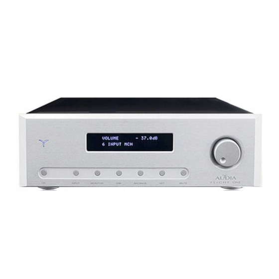
Pigiando tale pulsante, infatti, il LOGO blu si accenderà in modalità fissa ed il display indicherà, per circa quattro secondi “AUDIA FLIGHT ONE” (fig. 1, a pag. 45) e successivamente sulla prima riga il valore del volume (in decibel di attenuazione), mentre sulla seconda riga l’ingresso selezionato (fig. -
Page 16: Monitor
• Monitor Quando attivo, è possibile utilizzare questo ingresso per ascoltare (monitorizzare), attraverso i diffusori, ciò che si sta registrando dall’uscita “rec out”. Pigiando il pulsante “MONITOR” (part. 3, a pag. 47) apparirà l’indicazione dell’ingresso selezionato seguito dall’indicazione “monitor” (fig. 4 a pag. 45). NON è’... -
Page 17: Funzioni Speciali
Queste funzioni, tutte attivabili attraverso il pulsante “SET” (part. 6, a pag. 47), vi permetteranno di modificare le caratteristiche funzionali del vostro amplificatore integrato AUDIA Flight One. Per “entrare” nei vari menù, dopo aver pigiato il pulsante “SET”, occorre selezionare con la manopola quello occorrente e quindi pigiare di nuovo il pulsante “SET”. -
Page 18: Load Default
(fig. 13, a pag. 46). E’ possibile utilizzare il telecomando per questa funzione. • Software version Con questa indicazione potere leggere la versione del software utilizzato per la gestione del vostro amplificatore integrato AUDIA Flight One. -
Page 19: Protezioni
PROTEZIONI L’amplificatore integrato AUDIA Flight One dispone di un sofisticato sistema di protezioni elettroniche per la salvaguardia dei vostri diffusori e dell’amplificatore stesso. L’intervento delle protezioni può essere causato dai seguenti motivi: • Alta temperatura dispositivi di amplificazione Nel caso in cui la temperatura dei dissipatori interni dovesse superare la soglia di 75 °C. -
Page 20: Funzionamento
TELECOMANDO • Funzionamento Il funzionamento del telecomando è molto intuitivo. Infatti sulla tastiera sono riportati gli stessi comandi presenti sul frontale del amplificatore, ad eccezione del tasto “MONITOR” (funzione selezionabile solo dal pannello frontale) e della manopola multifunzionale, sostituita sul telecomando da due tasti, “+” e “-“. •... -
Page 21: Consigli Per L'ascolto
L’amplificatore AUDIA Flight ONE permette di riprodurre microdettagli e sfumature difficilmente evidenziabili; per migliorare le prestazioni del Vostro sistema di riproduzione, si consiglia di ottimizzare tutti i componenti e interconnessioni. -
Page 22: Filosofia Di Progetto
FILOSOFIA DI PROGETTO Da decenni il disegno circuitale della maggior parte dei progetti realizzati nell’amplificazione si basa, essenzialmente, su un circuito differenziale che, nel corso degli anni e con l’utilizzo di componentistica dalle prestazioni sempre più spinte, ha portato alla realizzazione di apparecchi davvero notevoli sul punto di vista sonoro. -
Page 23: Descrizione Tecnica
DESCRIZIONE TECNICA Il vostro amplificatore è composto da quattro sezioni ben distinte tra loro. Preamplificatore I circuiti di preamplificazione ed i relè per le commutazioni sono stati montati a ridosso del pannello posteriore, al fine di ridurre al massimo la distanza tra connettori di ingresso e gli stessi circuiti. -
Page 24: Caratteristiche Tecniche
Caratteristiche tecniche - Potenza di uscita rms 8 ohm 4 ohm 100 W 180 W - Guadagno stadio di amplificazione 26 Db - Risposta in frequenza ( - 3 dB ) 3 Hz ÷ 500 KHz - Slew-Rate > 180 V/μS - Distorsione armonica totale (THD) <... -
Page 25: Safety Instructions
SAFETY INSTRUCTIONS We encourage you to carefully read all operating and safety instructions listed below before attempting to use your AUDIA FLIGHT ONE. • Always disconnect the unit from the main power network before plugging or unplugging any connecting cable or when any component of the audio system is subject to maintenance. -
Page 26: Transport And Unpacking
Bring the box near the location place, then open it. CONTENT OF THE PACKAGE FLIGHT ONE is delivered with a detailed instruction manual, screened mains power cord, link cable and remote control, with batteries and tool for their replacement. Keep the package for possible shipping. -
Page 27: Generalities
AUDIA Flight ONE is made of two high-bias power sections, with output power of 100 W on 8 ohm, and six preamplifiers to secure the possible insertion in multi-channel amplification chains, getting the highest reproduction quality, in particular if in combination with the 3- channel dedicated amplifier AUDIA Flight 3.100 for the amplification of the remaining... -
Page 28: Input Connections For Stereo Operation
It is possible to plug in an optional Phono board, the “FL PH1”, inside the unit, which allows to exploit the “1” input as a phono input. To connect the turntable ground to the AUDIA Flight One amplifier chassis, use the dedicated “Ground” post (see also part 21 at page 47). -
Page 29: Input Connections For Multi-Channel Operation
In this way, you can adjust the volume level of the whole system by means of just the knob of your integrated amplifier that controls all six internal preamplifiers of the AUDIA Flight One. For each input it is possible to set a gain offset (+/- 12 dB). (For a detailed explanation, refer to the “ADVANCED FUNCTIONS”... -
Page 30: Output Connections - Out Pre Stereo Or Multi-Channel
Never connect the “out pre” terminals to each other. STEREO MODE In the case when the AUDIA Flight One amplifier is being used in a stereo (not multi-channel) system, it is possible to use the pre-amplified outputs, named “Front L” e “Front R” (see also part. -
Page 31: Output Connections - Rec Out
OUTPUT CONNECTIONS – REC OUT CAUTION NEVER SHORT-CIRCUIT the “rec out” output terminals. NEVER CONNECT to each other the “rec out” terminals of the two channels. On this output (see part 17, page 47) it is always present the signal of the selected input, at a level equal to that of the input signal, independently from the playback level. -
Page 32: Speaker Connections
POWER OUTPUT CONNECTIONS CAUTION NEVER SHORT-CIRCUIT the amplifier output terminals. NEVER CONNECT the amplifier output terminals to any device other than loudspeakers. NEVER CONNECT the left channel output terminals to the right channel output terminals. The unit is however provided with a safety device against short circuits in the output terminals. In case, the amplifier turns off (for additional information, refer to the section “PROTECTION”... -
Page 33: Communication Link
In order to do that you have to insert the provided digital connection cable in one of the two proper terminals located on the back of the unit (see part 19, page 47); analogously the other end of the cable must be inserted in the other unit. -
Page 34: Ac Mains Connection
The absence of an earthed outlet could be cause of malfunction (refer also to the section “SAFETY INSTRUCTIONS” at page 25). Flight ONE has a “SOFT START and SOFT OFF” main circuit. -
Page 35: Functions And Commands
The position “6”, named on the display “INPUT A/V”, select the six inputs corresponding to the “multi-channel” mode”. To select one input you only have to press the “INPUT” button (part. 2 at page 47) and use the multi-functional knob to select the required input. -
Page 36: Monitor
• Monitor When active, you can use this input to listen (“to monitor”), through the speakers, what you are recording at the “rec out” output. Pressing the “MONITOR” button, (part. 3, at page 47) the selected input will appear on the left-hand side of the second line of the display, followed by the “monitor”... -
Page 37: Advanced Functions
To “enter” the available menus, after pressing the “SET” button, you select the needed one with the multi-functional knob and then again press the “SET” button. All changes are stored and remain in the memory even in absence of power. -
Page 38: Load Default
(Master) or if it must receive them (Slave, fig. 13 at page 46). You can use the remote control for this function • Software version With this indication you may read the software version used to manage the operation of your AUDIA Flight One. -
Page 39: Protections
PROTECTIONS The AUDIA Flight One integrated amplifier is endowed with a sophisticated electronic protection system to safeguard your loudspeakers and itself. The operation of the protection system can be activated by the following reasons: • High temperature of the output stages In the case in which the temperature of internal heat sink should exceed the threshold of 75°C. -
Page 40: Remote Control
REMOTE CONTROL • Operating The operation of the remote control is very clear. In fact you can find on the remote control keyboard the same controls as those on the front panel of the amplifier, except for the “MONITOR” (this function can be selected only through the button on the panel) and the multi-functional knob, which is replaced by two buttons, “+”... -
Page 41: Listening Tips
The amplifier AUDIA Flight One is capable of revealing extremely subtle nuances and details of recorded music; to maximize the performance of your reproduction system, we recommend you to optimize all associated components and interconnections. -
Page 42: Design Concept
Obviously, beside developing a new technology in amplification design, we spent a lot of energy in looking for first class components, both for the quality and the performance, for clean signal paths, for unique transformers, all that is needed so that AUDIA products be, all in one, SUPERB! -
Page 43: Technical Notes
Each of the two independent amplification modules disposes of a 300VA audio dedicated toroidal transformer. There are two distinct supply stages for each module; a stabilized one feeding all circuits up to the drivers; the second one feeding the power output stage. -
Page 44: Specifications
Technical specifications - RMS output power 8 ohm 4 ohm 100 W 180 W - Gain of the amplification stage 26 Db - Frequency response ( - 3 dB ) 3 Hz ÷ 500 KHz - Slew-Rate > 180 V/μS - Total harmonic distortion (THD) <... -
Page 45: Indicazioni Display
Fig. 1 AUDIA FLIGHT ONE Fig. 2 VOLUME -90.0 dB 1 INPUT Fig. 3 VOLUME -90.0 dB 1 INPUT <INP Fig. 4 VOLUME -90.0 dB 1 INPUT MONITOR Fig. 5 DIMMING LEVEL 1 INPUT Fig. 6 100 % BALANCE 100 % 1 INPUT Fig. - Page 46 Fig. 10 SET PHASE INPUT 1 INPUT Fig. 11 SET GAIN A/V 1 FRONT L Fig. 12 SET EDIT 1 INPUT Fig. 13 SET LINK PRIORITY MASTER Fig. 14 LOAD DEFAULT CONFIRM?
Need help?
Do you have a question about the ONE and is the answer not in the manual?
Questions and answers