
Related Manuals for HealthCare International RehabMill

Summary of Contents for HealthCare International RehabMill
- Page 1 Owner’s Manual HealthCare International, Inc. PO Box 1509, Langley, WA 98260 www.HCIFitness.com – sales@hcifitness.com P: (360) 321-7090 or (800) 398-912...
-
Page 2: Table Of Contents
Table of Contents Important Safety Information Before You Start / Machine Maintenance Guide Machine Overview Accessory List 9-10 Assembly Instruction 11-21 Console Overview 22-28 Using Instruction Trouble Shooting 30-32 Exploded View Part List 34-36... - Page 3 Safety Precautions This exercise equipment was designed and built for optimum safety. However, certain precautions apply whenever you operate a piece of exercise equipment. Be sure to read the entire manual before assembly and operation of this machine. Also, please note the following safety precautions: 1.
- Page 4 Wishing you the best of luck in reaching your health and fitness goals! 。 HealthCare International is leading supplier and distributor of innovative products for Health, Wellness, www.HCIFitness.com Fitness Active Aging. Visit our website - for information on all of our &...
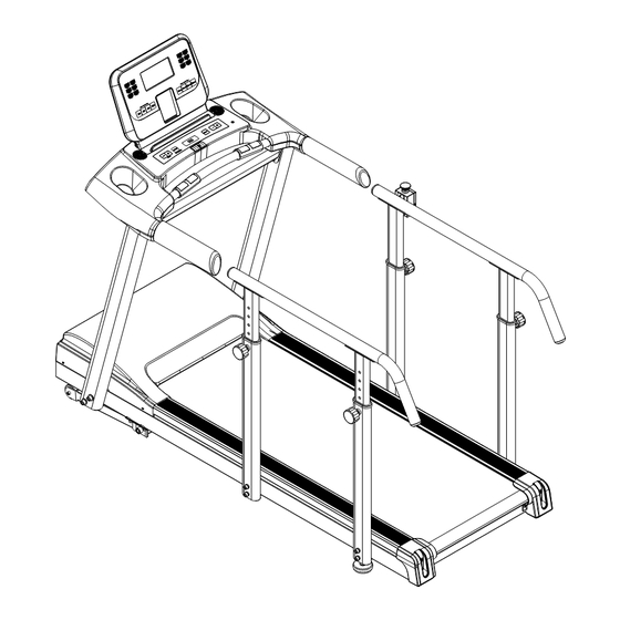
- Page 5 Treadmill Overview...
- Page 6 Components List PART NO. ITEM Main Frame 1 PC Console Connecting Tube 1 PC Left Upright Post 1 PC Right Upright Post 1 PC A02+F02 Display Shroud 1 SET Side Support Post (Long) Side Support Post (Short) Auxiliary Handrail 2 PCS Console/Monitor 1 PC Power Cord...
-
Page 7: Assembly Instruction
Assembly Instruction First Take out all parts from the carton and check if whole qty are coincident with Componenet List (Page 8 & 9), then place the treadmill onto flat, even floor. Step 1: Remove the fixed screws(B05X7) from the Motor Cover (F01),then open the Motor Cover(F01) - Page 8 Assembly Instruction Step 2: Connect Controller Wire(Middle Part) (H10) which is from the Right Upright Post (A05) to the Controller Wire(Lower Part) (H11) which is from Bottom Support Base. Step 3: Insert the Left & Right Upright Post (A04&A05) into the Bottom Support Base and make a loose connection with the following parts.
- Page 9 Assembly Instruction Step 4: Attach the Console Connecting Tube (A03) to Left & Right Upright Post (A04&A05) using the following parts to make a loose connection. DO NOT TIGHTEN ALL THE WAY UNTIL STEP 5 – Part 3. Qty4 – (B03) M5x15L Cross Head Screw (Sliver)
- Page 10 Assembly Instruction Step 5: Part 1: Connect the Controller Wire(Middle Part) (H10) which is from the Right Upright Post(A05) to the Controller Wire(Upper Part) (H09) wire which is out from the backside of the Display shroud (A02). Attach the Display Shroud (F02+A02) to the Left & Right Upright Post(A04&A05) respectively, per the following parts .
- Page 11 Assembly Instruction Step 6: Re-Install the Motor Cover (F01) to the Main Frame (A01) with Screws (B05 X 7 ) ( as shown as below Diagram )
- Page 12 Assembly Instruction Step 7: Part 1: Connect the Extension Wire (H13) 、Controller Wire(Upper Part)(H09)、Hand Pulse Wires(H12) to the wires respectively which are out from the backside of Console (H01) as the diagram. Part 2: Attach the the Monitor Support Bracket (A07) to the Cargo Holder Case Support Bracket (A02), per the following parts .
- Page 13 Assembly Instruction Step 8: Install the Left& Right Upright Post Bottom Collar (F03&F04) and Cargo Holder Case Assy(F02) onto the Cargo Holder Case Support Bracket (A02) ,then Secure together with 6PCS TP4x12L Screw (Sliver) (B01) and 2PCS Plastic Dowel Pin (G04).
- Page 14 Assembly Instruction Step 9: Part 1: Connect the connector which is from the Emergency Switch (H03) to the Emergency Switch Jack (H19) wire which is out from the Control Board ( High Speed) (H17) as the diagram. Part 2: Install the Side Support Posts (Long&Short)(A08&A09) to two sides of the Main Frame(A01) respectively as the diagram , per the following parts .
- Page 15 Assembly Instruction Step 10: Lock two side Auxiliary Handrails (A12) into the Side Support Adjustment Posts (Long & Short) (A10&A11) respectively as the diagram , per the following parts . M8 x20 L Hex Head Screw (Sliver) Qty 8 –(B08)
- Page 16 Assembly Instruction Step 11: This machine only can be powered by using the Power Cord(H02) , please make sure the Power Cable has already been plugged into the power jack on the front part of the frame. (as showed on the drawing) Congratulations! You have completed the assembly of your new Treadmill!
-
Page 17: Console Overview
Console Overview 1. Specifications: (1) Programs including: 1Manual, 7 preset programs, 2USER, 2HRC,and Body Fat. P0: Manual (field mode) P5: Mountain User1 P1: Plateau P6: Rolling User2 P2: Fat Burn P7: Plateau P3: Random Hrc1 P4: Interval Hrc2 (2) Hear Rate detection:handgrip(standard), and wireless receiver(optional). (3) P1 ~ P7, those preset program will change the speed. - Page 18 2. LCD display: Full lighting view 3. Keys function: Key tone: While user press any key, will beep once. Main keys: (1) INCLINE UP: Increase incline; While in standby, choose program or adjust data value. (2) INCLINE DOWN: Decrease incline; While in standby, choose program or adjust data value. (3) ENTER/Mode:...
- Page 19 (2)、SPEED 2: Directly setting Speed to8KPH /5MPH (3)、SPEED 3: Directly setting Speed to10KPH/6MPH (4)、SPEED 4 : Directly setting Speed to12KPH/7MPH 4. Operating & Control: (1)Be sure the Safety key on, open the power switch on the treadmill deck, screen will fully display 2 seconds, and enter the standby mode. (2)If release the Safety key, system will turn off immediately.
- Page 20 (13)Pace Steps: Calculate the number of steps. (For estimate, provide user reference only.)
- Page 21 Program List: P0: Manual: P1: Plateau P2: Fat Burn P3: Random P4: Interval P5: Mountain P6: Rolling P7: Plateau 2 User1 User2 HRC1 HRC2...
- Page 22 HRC (Heart Rate Control) : (1) While in Standby mode, use arrow keys to choose the program H1/H2. (HRC1 display in H1),And press enter key to enter the HRC program. (2) Target heart rate pending on the Age, setting range from 10 to 99 years old. (3) HRC1formula (216-Age) *65%,i.e.
- Page 23 USER (User define) : (1) Use arrow keys to choose U1/U2. And press enter key to enter the User program. (2) PressENTER(MODE) and use the arrow keys to adjust the speed value, from SPEED1 to SPEED10. (3) USER press START key to start the program. (4) Speed bar will change next in per 5min.
- Page 24 7.Error message and debug: E1: No speed detected.。 (1) Check speed sensor, loosen or broken. Speed sensor should closer with magnet in 2 to 3 mm. (2) Check sensor connector attached to controller property. E2: System Data lost (1) Check EEROM loosen, replace EEPROM IC. E6:Incline reverse (1) Incline motor wire reverse,switched red/black wire.
-
Page 25: Trouble Shooting
Trouble Shooting Here are some solutions for simple technical support , please identify your problem first ,then follow the indication for fixing the problem , if they still not work , please consult to local distributor or producer for further assistance. Problem Possible reason Method... - Page 26 c. After adding, build up the treadmill and start it with the speed 1Km/h.And with one foot tramples the running belt slightly for several minutes, to let the running belt absorb the lubrication well. 2. Adjustment for Running belt tension All treadmills’...
- Page 27 PS: Turn the Wrench clockwise mean tighten the left side of Rear Roller Axle (E03) to make the running belt to lean slowly to right side , but turn counterclockwise will loose the left side of Rear Roller Axle to make running belt to lean to left side.
- Page 28 EXPOLRE VIEW...
-
Page 29: Part List
PART LIST... - Page 30 ITEM Main Frame Cargo Holder Case Support Bracket Connecting Tube Left Upright Post Right Upright Post Front Elevation Frame Monitor Support Bracket Side Support Post (Long) Side Support Post (Short) Side Support Adjustment Post (Long) Side Support Adjustment Post (Short) Auxiliary Handrail Elevation Frame Mount Base TP4x12L Screw (Sliver)
- Page 31 M16 Nylon Nut(Sliver) M10 Flange Nut(Sliver) M6 Nylon Nut(Sliver) Ø8.2 x Ø19 x 1.5T Washer Ø10.2 x Ø20 x 2.0T Washer Ø12 x Ø25 x 2.0T Washer Ø16 x Ø32 x 3.0T Washer Ø4 External Tooth Washer Ø8.0 Spring Washer Ø12 x 3.0T Adjusted Washer Front Roller Rear Roller...
- Page 32 Running Belt PE Spacer End Plug Anti-Slip Strip Low Speed Transmission Belt (A) Low Speed Transmission Belt (B) Side Support Adjustment Post Bushing Console/Monitor Power Cord Emergency Switch Power Jack Electricity Protector Power Switch Incline Motor Ground Wire Controller Wire(Upper Part) Controller Wire(Middle Part) Controller Wire(Lower Part) Hand Pulse Grip w /Wire...
Need help?
Do you have a question about the RehabMill and is the answer not in the manual?
Questions and answers