
Summary of Contents for Bohn PRO3
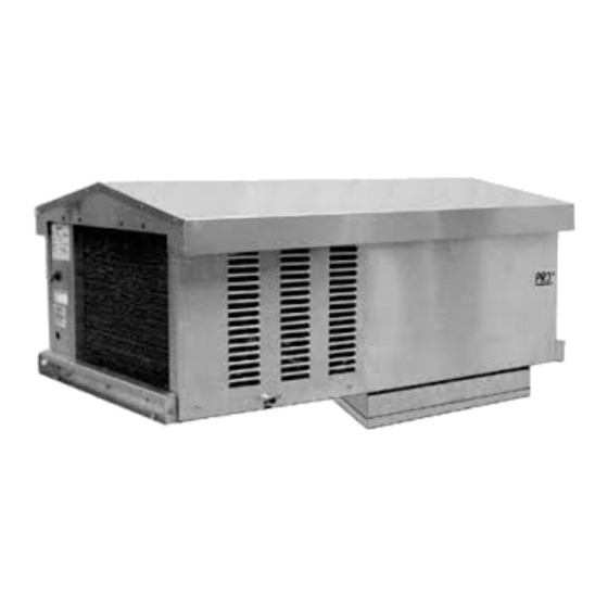
- Page 1 BN-H-IM-82D | FEBRUARY 2020 Part #25002401 TOP MOUNT PACKAGED REFRIGERATION SYSTEM Installation and Operations Manual For Outdoor Applications...
-
Page 2: Table Of Contents
P R O T O P M O U N T P A C K A G E D R E F R I G E R A T I O N S Y S T E M TABLE OF CONTENTS Owner’s Manual Installation Instructions Dimensional Diagrams Space and Locations Requirements... - Page 3 DIMENSIONAL DRAWINGS FIGURE A FIGURE 2 - B CABINET DESIGN FIGURE 2 - B CABINET DESIGN P2 Cabinet Dimensions Without Weather Hood 28.5" 72.4cm 28.5" 72.4cm WITH WEATHERHOOD: 33.8" (85.85 cm) WITH WEATHERHOOD: 33.8" (85.85 cm) 20" 20" 50.9cm 50.9cm 17.5"...
-
Page 4: Recommended Unit Placement
P R O T O P M O U N T P A C K A G E D R E F R I G E R A T I O N S Y S T E M RECOMMENDED UNIT PLACEMENT FOR OUTDOOR MODELS Some general rules for the evaporator section placement which must be followed are:... -
Page 5: Rigging
RIGGING MOUNTING Rigging holes are provided on all models. Caution should The system requires an opening in the ceiling to the be exercised when moving these units. To prevent damage dimensions stated on page 3. Mounting rails are located to the unit housing during rigging, cables or chains used at both ends of the chassis. -
Page 6: Standard Installation Procedure
P R O T O P M O U N T P A C K A G E D R E F R I G E R A T I O N S Y S T E M THE OUTDOOR PRO COMES STANDARD WITH THE FOLLOWING ADDITIONAL COMPONENTS: Crankcase Heater... - Page 7 OUTDOOR MODELS Example Outdoor Curb Installation (Curb supplied by others) This area of curb may be solid. Figure Curb placed on roof of walk-in cooler. Figure 2. Roof membrane placed over curb. Note: Do not caulk around the base of compressor compartment.
-
Page 8: Service Information
ELECTRIC DEFROST SEQUENCE OF OPERATION FOR FREEZERS PRO3 SYSTEM STANDARD MAINTENANCE GUIDELINES During normal operation, at the preset time intervals, After first year of operation and under normal usage, the temperature/defrost control will de-energize the... - Page 9 REFRIGERATION/DEFROST SEQUENCE OF OPERATION The sequence of operation varies depending on the model that has been installed. The three basic models are Low Temperature, Medium Temperature, and High Temperature models. The particular model can be determined by the seventh digit of the model number. See Tables 1-3 for details and settings. Control of the refrigeration and defrost system is provided by the Carel controller along with a space (box) temperature sensor and a coil (defrost) temperature sensor.
- Page 10 P R O T O P M O U N T P A C K A G E D R E F R I G E R A T I O N S Y S T E M TABLE 3: OUTDOOR MEDIUM TEMPERATURE MODELS-ELECTRIC DEFROST | EZY SETTING=2 SET POINT IS 35°...
- Page 11 PROGRAMMING THE PJEZC CAREL INSTALLATION AND REMOVAL ELECTRONIC CONTROLLER PANEL INSTALLATION FROM THE FRONT Reprinted with permission from Carel. USING SCREWS The thickness of the fastening panel must not ■ The Carel PJEZC control is a fully configurable electronic exceed 3 mm. refrigeration controller.
- Page 12 P R O T O P M O U N T P A C K A G E D R E F R I G E R A T I O N S Y S T E M ELECTRICAL CONNECTIONS DISPLAY WARNINGS: The electrical connections must only be completed by a...
- Page 13 KEYPADS PRELIMINARY CONFIGURATIONS Once the electrical connections have been completed, simply power-up the controller to make it operative. Heatcraft recommends that you check the parameters listed. Control Parameters set point set point differential Defrost Parameters type of defrost Normal Operation But.
- Page 14 P R O T O P M O U N T P A C K A G E D R E F R I G E R A T I O N S Y S T E M WARNING: /5: SELECT °C/°F Defines the unit of measure used for temperature control.
- Page 15 RAPID PARAMETER SET SELECTION (EZY) NOTE: The easy controller features the EZY parameter which To restore the selected rapid parameter set at any ■ is used to quickly choose a list of parameters, with time, turn the controller off and on again, while holding corresponding values, for the control of the refrigeration SET.
- Page 16 P R O T O P M O U N T P A C K A G E D R E F R I G E R A T I O N S Y S T E M DESCRIPTION OF THE MAIN SIGNALS AND ALARMS HI FLASHING LED FLASHING High temperature alarm.
- Page 17 MODIFYING THE PARAMETERS WARNINGS: PARAMETER NAVIGATION If no button is pressed for 60 s, all the changes made to The operating parameters, modifiable using the keypad, the parameters, temporarily saved in the RAM, will be are divided into two types: frequent (type F) and canceled and the previous settings restored.
- Page 18 P R O T O P M O U N T P A C K A G E D R E F R I G E R A T I O N S Y S T E M TROUBLESHOOTING The following table shows a number of situations that may occur on the various models. The most frequent causes and corresponding checks are described: Problem Cause...
- Page 19 DEVICE SETUP Set 1 - Low Temperature Models - Electric Defrost w/ -10° F Set Set o Set 1 Set 2 Set 3 Set 4 Parameter Description Default Set point Minimum set point value Maximum set point value Minimum compressor off time Type of Defrost Interval between defrost End defrost temperature set point...
-
Page 20: System Troubleshooting Chart
P R O T O P M O U N T P A C K A G E D R E F R I G E R A T I O N S Y S T E M Table 5: PRO System Troubleshooting Chart PROBLEM POSSIBLE CAUSES... -
Page 21: Replacement Parts
InterLink™ is your link to a complete line of dependable and certified commercial refrigeration parts, accessories and innovative electronic controls for all Bohn equipment. At InterLink, we provide our wholesalers with a www.interlinkparts.com comprehensive selection of product solutions and innovative technologies 800.686.7278... -
Page 22: Electrical Wiring Diagrams
P R O T O P M O U N T P A C K A G E D R E F R I G E R A T I O N S Y S T E M ELECTRICAL WIRING DIAGRAMS ELECTRIC DEFROST SYSTEMS - SINGLE PHASE - P2 CABINET PRIMARY SINGLE PHASE PROTECTION PROVIDED PRIMARY SINGLE PHASE PROTECTION PROVIDED... - Page 23 ELECTRICAL WIRING DIAGRAMS AIR DEFROST SYSTEMS - SINGLE PHASE - P2 CABINET PRIMARY SINGLE PHASE PROTECTION PROVIDED PRIMARY SINGLE PHASE PROTECTION PROVIDED USE COPPER CONDUCTORS ONLY FACTORY WIRING FIELD WIRING (WHEN PLUG BLUE PROVIDED) 208-230V/1ø/60HZ BLACK GRAY GRAY BLACK BLUE BLACK BLACK BLACK...
- Page 24 P R O T O P M O U N T P A C K A G E D R E F R I G E R A T I O N S Y S T E M ELECTRICAL WIRING DIAGRAMS ELECTRIC DEFROST SYSTEMS - SINGLE PHASE - P3 CABINET PRIMARY SINGLE PHASE PROTECTION PROVIDED PRIMARY SINGLE PHASE PROTECTION PROVIDED...
- Page 25 ELECTRICAL WIRING DIAGRAMS AIR DEFROST SYSTEMS - SINGLE PHASE - P3 CABINET PRIMARY SINGLE PHASE PROTECTION PROVIDED PRIMARY SINGLE PHASE PROTECTION PROVIDED USE COPPER CONDUCTORS ONLY FACTORY WIRING FIELD WIRING (WHEN PLUG BLUE PROVIDED) 208-230V/1ø/60HZ BLACK GRAY GRAY BLACK BLUE BLACK BLACK BLACK...
- Page 26 P R O T O P M O U N T P A C K A G E D R E F R I G E R A T I O N S Y S T E M ELECTRICAL WIRING DIAGRAMS ELECTRIC DEFROST SYSTEMS - THREE PHASE - P3 CABINET PRIMARY SINGLE PHASE PROTECTION PROVIDED PRIMARY SINGLE PHASE PROTECTION PROVIDED...
- Page 27 ELECTRICAL WIRING DIAGRAMS AIR DEFROST SYSTEMS - THREE PHASE - P3 CABINET PRIMARY SINGLE PHASE PROTECTION PROVIDED PRIMARY SINGLE PHASE PROTECTION PROVIDED USE COPPER CONDUCTORS ONLY FACTORY WIRING FIELD WIRING (WHEN PLUG PROVIDED) 208-230V/3ø/60HZ BLACK BLACK GRAY GRAY BLUE BLACK BLACK BLACK BLACK...
- Page 28 P R O T O P M O U N T P A C K A G E D R E F R I G E R A T I O N S Y S T E M WARRANTY STATEMENT consequential or penal damages, or for any expenses incurred Heatcraft Refrigeration Products LLC warrants to its direct purchasers that the PRO...
- Page 29 NOTES...
- Page 30 P R O T O P M O U N T P A C K A G E D R E F R I G E R A T I O N S Y S T E M NOTES...
- Page 31 NOTES...
- Page 32 2175 West Park Place Blvd. Stone Mountain, GA 30087 Phone: 800.537.7775 · Fax: 770.465.5900 heatcraftrpd.com Since product improvement is a continuing effort, we reserve the right to make changes in specifications without notice. BN-H-IM-82D-0220 | Version 001 ©2020 Heatcraft Refrigeration Products LLC...
Need help?
Do you have a question about the PRO3 and is the answer not in the manual?
Questions and answers