
Related Manuals for Vimar Eikon 20493


Summary of Contents for Vimar Eikon 20493
- Page 1 Eikon Arké Idea Plana 20493 19493 16943 14493 Manual to configure the radio-frequency devices when used with the burglar alarm via bus system. Instructions...
-
Page 3: Table Of Contents
Radio interface (Eikon 20493, Arké 19493, Idea 16943, Plana 14493) ....... -
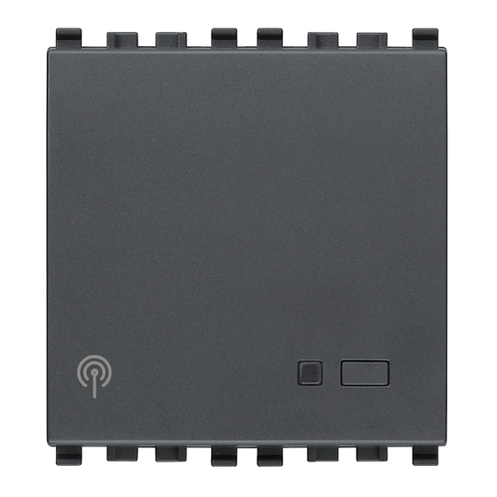
Page 4: Radio Interface (Eikon 20493, Arké 19493, Idea 16943, Plana 14493)
Radio interface Technical characteristics - Rated supply voltage (Vn): BUS 20-30 V d.c. The radio interface allows using the radio frequency devices to - Protection class: IP30 extend coverage in places or accesses where it is not possible to - Operating temperature: -5 -- +45 °C (for indoor use) add any cables and devices via BUS. - Page 5 List of Radio frequency devices that can be used VIMAR code DESCRIPTION / COMPOSITION 01819 Two-way remote control 01737 Passive infrared intrusion detector, battery power supply (supplied). 01738 Magnetic contact for doors and windows, battery power supply (supplied). 01744 Water detector for protection against flooding, battery power supply (supplied).
- Page 6 Operation Note: If the intrusion detection alarm system is turned on and a contact has accidentally been left open (a window for instance), The device receives the transmissions of the radio wave signals the system will not turn on and the control panel will display the emitted by the radiofrequency devices and by the remote control.
- Page 7 • red/green two-colour LED blinking: 6) Activation delay zones from 20 to 30: 0 s = instantaneous. It can - it blinks for a few seconds after the phase of resetting the device. be increased up to 60 s in steps of 1 s. Note: If a radio frequency detector for alarms of a technical type (water detector, for instance) is configured in the same zone as a Settings (programmable via the control panel)
-
Page 8: Remote Control (01819)
Remote control (01819) Technical characteristics - Power supply: 2 alkaline batteries 3 V CR2016 The remote control has 4 keys to transmit 4 different com- - Radio range: 100 m in an open field mands to the radio interface. The radio interface commu- nicates these commands to the control panel. - Page 9 LED indicators The various PANIC functions are mutually exclusive. • blinking orange: code transmission To silence the sirens turn the system on and off with the remote control • green: system off or interface in off zone by pressing the ON (1 and 2) and OFF buttons in sequence, or on the • red: system on or interface in active zone control panel with “Alarm Reset”...
- Page 10 Inserting/changing batteries. The power supply is provided by 2 alkaline batteries CR2016 3 V. CR 2016 CR 2016 CR 2016 • Change the batteries solely with ones of the same type. • Connect the batteries observing the correct polarity. • If scrapping the remote control, the batteries must be taken WARNING: Dispose of batteries in the specific differentiated out beforehand. collection bins. 8 - ENGLISH...
-
Page 11: Infrared Detector (01737)
Infrared detector (01737) Technical characteristics - Power supply: 9 V alkaline battery type 6LR61 The infrared presence detector 01737, installed in the rooms - Cover: angle 90°, distance 10 m to surveil, is able to generate an alarm message when it - Volumetric cover: 17 sectors on 3 floors (with a range of 10 m) detects motion of heat-emitting bodies in its areas of cove- and 11 sectors on 2 floors (with a range of 5 m) - Page 12 Connection example Connections N/C contact 1 2 3 4 1 2 3 4 10 - ENGLISH...
- Page 13 Inserting/changing battery. • Change the battery solely with one of the same type. • Connect the battery observing the correct polarity. • If scrapping the detector, the battery must be taken out beforehand. 6 L R o l t WARNING: Dispose of batteries in the specific differentiated collection bins. ENGLISH - 11...
- Page 14 The angle of coverage is 80°/90° horizontally for a reach Operation of 10 m. Installation must be at a height of between 2.10 • It detects motion of heat-emitting bodies in its areas of coverage. m and 2.50 m off floor level. • Opening the contact that may be connected will cause an alarm warning that can be made to differ from that of the IR sensor (to distinguish between different break-ins) by using the detector’s...
- Page 15 Configuring the infrared detector 01737 Dip-switches Warning: To configure the infrared sensor, all the dip switches must be OFF. - Prepare the control panel for configuring the radio-frequency devi- ces (see the control panel manual). - Open the enclosure. 1 2 3 4 1 ON = Maximum range equal to approximately 10 m 1 OFF = Maximum range equal to approximately 5 m 2 ON = Selector for configuring the N/C input.
- Page 16 - Put the dip-switches 1,3 and 4 onto the desired position and - If the N/C contact is used too, prepare the control panel leave 2 OFF (the dip-switches must be positioned before for configuration (the detector connected to the N/C contact inserting the battery).
- Page 17 Warning: - do not subject it to the direct action of sources of heat; - do not place any objects in front of the infrared sensor (plants, curtains, furniture, etc.); - do not place it in the direction of sources of heat. - do not expose it to direct light from lamps or sunlight;...
-
Page 18: Detector With Magnetic Contact For Doors And Windows (01738)
Technical characteristics Detector with magnetic contact for doors and windows (01738) - Power supply: alkaline battery 9 V 6LR61 - Operating temperature: from -5 °C to +45 °C The magnetic contact detector enables surveilling the ope- - Protection class: IP30 ning of a door and/or window in the room. - Page 19 Connections N/C contact 1 2 3 4 1 2 3 4 ENGLISH - 17...
- Page 20 Inserting/changing battery. • Change the battery solely with one of the same type. • Connect the battery observing the correct polarity. • If scrapping the detector, the battery must be taken out beforehand. 6 L R o l t WARNING: Dispose of batteries in the specific differentiated collection bins. 18 - ENGLISH...
- Page 21 Funktionsweise • Walktest: During this phase an alarm is generated so as • Moving the magnet away from the body of the sensor (and to check that the device works properly. In addition, the moving it nearer) causes radio transmissions for opening control panel identifies the type of detector and provides (and closing) the door or window, signalling an alarm (and, an indication on the level of radio reception.
- Page 22 Dip-switches Configuring the detector with magnetic contact 01738 Warning: To configure the magnetic sensor, all the dip switches must be OFF. - Prepare the control panel for configuring the radio-frequency devices (see the control panel manual). 1 2 3 4 - Open the enclosure.
- Page 23 - Put the dip-switches 1 and 3 onto the desired position and - If the N/C input is used too, in the event of an alarm on leave 2 OFF (the dip-switches must be positioned before the magnetic contact or on the N/C contact the detector inserting the battery).
- Page 24 Warning: - Secure the magnet of the contact on the striker of the door or window at a distance from the contact of max 5 mm. - The electronic part of the contact (including the battery) must be secured at the top on the fixture of the door or window. - Fixtures that are made of metal or contain a metal structure can attenuate or completely cancel the strength of the magnet regardless of whether it is used correctly.
- Page 25 If the N/C contact is used with a rope detector for roller shutters: - Secure the rope contact inside the roller shutter box. - Use a single rope detector per device. max 2 m max 2 m 2 x 0,15 mm 2 x 0,15 mm ENGLISH - 23...
-
Page 26: Water Detector For Protection Against Flooding (01744)
Technical characteristics Water detector for protection against flooding (01744) - Power supply: 9 V alkaline battery type 6LR61 - Operating temperature: from -5 °C to +45 °C - Protection class: IP30 The detector installed in the rooms to protect activates the - Anti-sabotage protection against opening;... - Page 27 Inserting/changing battery. • Change the battery solely with one of the same type. • Connect the battery observing the correct polarity. • If scrapping the detector, the battery must be taken out befo- rehand. WARNING: Dispose of batteries in the specific differentiated collection bins. ENGLISH - 25...
- Page 28 Operation Configuring the water detector 01744 • In the protected room, it detects a water level higher than Prepare the control panel for configuring the radio- the threshold and signals the technical alarm to the control frequency devices (see the control panel manual). panel. - Open the enclosure. • The detector LED lights up when an alarm is detected. • Approximately every 30 minutes, the detector sends a correctly operating signal to the control panel (via radio interface).
- Page 29 - Prepare the control panel for configuring the detector then Warning: insert the battery into the device; the control panel will - Secure the flooding sensor near electrical household confirm reception of the message. The display will show a appliances (washing machine, dishwasher, etc.) or poten- configuration message.
-
Page 30: Siren For Outdoor Use (01747)
Technical characteristics Siren for outdoor use (01747) - Power supply: alkaline battery pack 9 V 12 Ah (art. 00912) - Operating temperature: from -25 °C to +55 °C The siren for outdoor use enables audible (can be heard far - Sound pressure level at 1 m: 110 dB away) and visual warning of all alarm conditions. - Page 31 Connections Trimmer for adjusting the loudness of the beeps Battery pack connector ENGLISH - 29...
- Page 32 Inserting/changing battery. • Change the battery solely with one of the same type. • Connect the battery observing the correct polarity and repe- at the configuration procedure. • If scrapping the siren, the battery must be taken out beforehand. WARNING: Dispose of batteries in the specific differentiated collection bins. 30 - ENGLISH...
- Page 33 Operation • Audible alarm governed by the control panel lasting 3 min. • Anti-sabotage protection: Opening the siren enclosure for each alarm cycle. causes the tamper alarm; before changing the batte- ry pack it is necessary to set the control panel on • Alarm signalling delay equal to approx. 12 s with audible Walktest. pre-alarm warnings (beeps). • Walktest: In this phase, the control panel identifies the type • Audible warning to confirm the system is on (1 beep), off of detector and provides an indication on the level of radio (2 beeps) and partitioned (3 beeps).
- Page 34 Siren configuration 01747 - Open the siren and secure it to the wall; configuration then takes place in two phases: 32 - ENGLISH...
- Page 35 1st Phase 2nd Phase - Prepare the control panel for configuration (see the con- - Close the siren; correct closure of the enclosure is confir- trol panel manual) then connect the battery pack to the med by an audible warning (beep) emitted by the siren. siren.
- Page 38 Viale Vicenza, 14 - I 36063 Marostica VI Tel. +39 0424 488 600 - Fax (Export) 0424 488 709 49400093B0EN 01 1210 http://www.vimar.com VIMAR - Marostica -Italy...
Need help?
Do you have a question about the Eikon 20493 and is the answer not in the manual?
Questions and answers