Table of Contents
Advertisement
Quick Links
WARNING: If the information in this man-
ual is not followed exactly, a fire or explo-
sion may result causing property damage,
personal injury or loss of life.
- Do not store or use gasoline or other flam-
mable vapours and liquids in the vicinity of
this or any other appliance.
- WHAT TO DO IF YOU SMELL GAS
• Do not try to light any appliance.
• Do not touch any electrical switch; do not
use any phone in your building.
• Immediately call your gas supplier from a
neighbour's phone. Follow the gas supplier's
instructions.
• If you cannot reach your gas supplier, call
the fire department.
- Installation and service must be performed
by a qualified installer, service agency or the
gas supplier.
California Proposition 65 Warning: This product contains chemicals known to the State of
California to cause cancer, birth defects, or other reproductive harm.
Installation and service manual
High efficiency condensing water heaters.
This manual must be
left with owner and
must be hung on or
adjacent to the water
heater for reference.
AVERTISSEMENT. Assurez-vous de
bien suivre les instructions données dans
cette notice pour réduire au minimum le
risque d'incendie ou d'explosion ou pour
éviter tout dommage matériel, toute bles-
sure ou la mort.
- Ne pas entreposer ni utiliser d'essence
ou ni d'autres vapeurs ou liquides inflam-
mables à proximité de cet appareil ou de
tout autre appareil.
- QUE FAIRE SI VOUS SENTEZ UNE
ODEUR DE GAZ :
•Ne pas tenter d'allumer d'appareils.
•Ne touchez à aucun interrupteur. Ne pas
vous servir des téléphones dans le bâtiment
où vous vous trouvez.
•Appelez immédiatement votre fournisseur
de gaz depuis un voisin. Suivez les instruc-
tions du fournisseur.
•Si vous ne pouvez rejoindre le fournisseur
de gaz, appelez le service des incendies.
L'installation et l'entretien doivent être as-
surés par un installateur ou un service
d'entretien qualifié ou par le fournisseur
de gaz.
Advertisement
Table of Contents

Related Manuals for Eco-King HWB-299

Summary of Contents for Eco-King HWB-299
- Page 1 Installation and service manual High efficiency condensing water heaters. HWB-299 HWB-399 HWB-499 WARNING: If the information in this man- AVERTISSEMENT. Assurez-vous de ual is not followed exactly, a fire or explo- bien suivre les instructions données dans sion may result causing property damage, cette notice pour réduire au minimum le...
-
Page 3: Table Of Contents
Return and Supply piping Tank .................. 33 HEATEXCHANGER RESISTANCE GRAPHS ................... 34 ........................34 YDRAULIC GRAPHS 9.1.1 Water heater resistance graph HWB-299 ..............34 9.1.2 Water heater resistance graph HWB-399 ..............34 9.1.3 Water heater resistance graph HWB-499 ..............35 . - Page 4 PVC/ CPVC ..........................40 10.3.1 Instructions for working with cementing PVC/ CPVC pipe connections: ....41 ........................42 OLYPROPYLENE 10.4.1 Flexible polypropylene ....................43 10.4.2 Stainless steel vent..................... 43 ....................44 EALED OMBUSTION IR SUPPLY 10.5.1 Combustion air quality ....................44 10.5.2 Air supply through humid areas ..................
- Page 5 ..................77 EMAND FOR OMESTIC ATER 13.8.1 DHW Storage with bulb sensor; DHW mode 1 ............77 13.8.2 DHW mode 4 ......................78 13.8.3 Anti-legionella protection..................... 79 13.8.4 Display menu structure summary................80 14 TEMPERATURE PROTECTION ......................87 15 ERROR INFORMATION........................87 .
- Page 6 IMPORTANT READ ALL OF THE FOLLOWING WARNINGS AND STATEMENTS BEFORE READING THE INSTALLATION INSTRUCTIONS DANGER Danger Sign: indicates the presence of an imminently hazardous situation that will cause death, serious personal injury or substantial property damage. WARNING Warning Sign: indicates the presence of a hazardous situation which can cause death, serious personal injury or substantial property damage.
-
Page 7: Safety Guidelines
SAFETY GUIDELINES E93.1801EN171 HWB installation manual... - Page 8 CONSIGNES DE SÉCURITÉ. E93.1801EN171 HWB installation manual...
- Page 9 This water heater is equipped with a pressure switch in the event of a blocked vent the wa- ter heater will lockout. No attempt by the user/owner should be made to put the water heater back into operation. A qualified service technician should be notified of the issue. The water heater should only be reset by a qualified service technician after they have di- CAUTION agnosed and corrected the issued that caused the safety lockout of the water heater.
- Page 10 WARNING: Water temperatures over 125 °F (52 °C) can cause severe burns instantly or death from scalding. The water temperature is factory set at 140 °F (60 °C) to minimize legionella risk. Before bathing or showering always check the water temperature. WARNING To meet commercial hot water requirements, the water heater setpoint is adjustable up to 190°F.
-
Page 11: Introduction
INTRODUCTION Ce manuel est écrit pour l'installateur et le technicien This manual is written for the installer and service tech- d'entretien. nician. Eco King Heating Products Inc. n'est pas responsable Eco King Heating Products Inc. is not accountable for de tout dommage causé par ne pas suivre correctement any damage caused by failure to correctly follow these de ces instructions. -
Page 12: For Installations In The Commonwealth Of Massachusetts
For installations in the Commonwealth of Massachusetts. The following local requirements apply in addition to all other applicable NFPA requirements: For direct- vent water heaters, mechanical-vent heating appliances or domestic hot water equipment, where the bottom of the vent terminal and the intake is installed below four feet above grade the following requirements must comply: 1) If not present on each floor level where there are bedrooms, a carbon monoxide detector and alarm must be placed in a living area outside the bedrooms. -
Page 13: Important Technical Warnings And Guidelines
Important technical warnings and guidelines Visually inspect the venting system for proper size and horizontal pitch and determine there is no blockage or restriction, leakage, corrosion and other deficiencies which could cause an unsafe condition. Maintenance and inspection of the water heater should be carried out at the following occasions: •... -
Page 14: Pressure Relief Valve
Firing the water heater without water flow (but filled with water) will cause a boiling noise. The Outlet and Inlet temperature are checked continuously. The temperature difference may not exceed the programmed value belonging to the actual power mode. If it does, the water heater will go in a lock-out. The applied DHW pump must be controlled only by the HW water heater control. - Page 15 The water heater and tank should be installed by a skilled installer according to all applicable standards and reg- ulations for tap water installations. Use the next scheme as guideline. When multiple water heaters and tanks are applied, every combination has to be equipped with its own safety valve. A) Potable water inlet B) Hot water supply circulation C) Circulation return...
-
Page 16: Technical Data Water Heaters
TECHNICAL DATA WATER HEATERS Functional introduction The HWB water heaters are central heating water heaters with a maximum high efficiency. Such a performance can be reached by, amongst other things, using a special heat exchanger made of stainless steel. This allows the flue gases to cool down below the condensation point, and so release extra heat. -
Page 17: Technical Specifications Datasheet
Technical specifications datasheet GENERAL Water heater, category Water heater model HWB-299 HWB-399 HWB-499 Dimensions (h x w x d) inch (mm) 33.3 x 17.3 x 20.9 (845 x 440 x 530) Gallon (liter) Water content (estimated) 1.32 (5.0) 2.19 (8.3) 2.74 (10.4) -
Page 18: High Altitude Operation
Water heater model HWB-299 HWB-399 HWB-499 EMISSION Values Low fire - High fire: Natural gas 9.8 - 9.2 flue gas Propane 11.0 - 10.4 Natural gas 3.7 - 4.7 flue gas Propane 4.1 - 5.0 Flue gas temperature at combustion air °F (°C) -
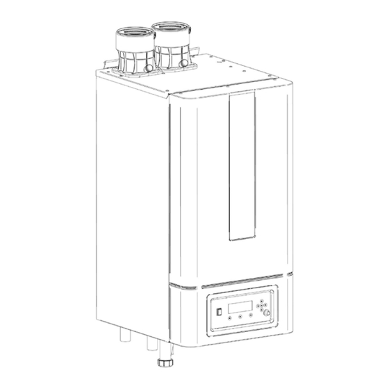
Page 19: Water Heater Dimensions
WATER HEATER DIMENSIONS HWB-299 Connections HWB-299 NPT 1½” Hot water outlet NPT 1½” Cold water inlet Condensate Flexible hose Ø 1.06 ” (26.9 mm) NPT 1” E93.1801EN171 HWB installation manual... -
Page 20: Hwb-399
HWB-399 Connections HWB-399 NPT 1½” Hot water outlet NPT 1½” Cold water inlet Condensate Flexible hose Ø 1.06” (26.9 mm) NPT 1” E93.1801EN171 HWB installation manual... -
Page 21: Hwb-499
HWB-499 Connections HWB-499 NPT 1½” Hot water outlet NPT 1½” Cold water inlet Condensate Flexible hose Ø 1.06” (26.9 mm) NPT 1” E93.1801EN171 HWB installation manual... -
Page 22: Accessories And Unpacking
WIFI module. / IP module S022.500.006 External Ignition transformer S022.500.005 Propane kit for VMS Venturi hole Ø 6.2 HWB-299 S022.500.001 Propane kit for VMS Venturi hole Ø 6.7 HWB-399 S022.500.003 Propane kit for VMS Venturi hole Ø 7.2 HWB-499 S022.500.004... -
Page 23: Installation Location Of The Hwb
INSTALLATION LOCATION OF THE HWB Installation Clearances On all sides of the water heater at least 2” of clearance should be applied to walls or wall units, 14” above the top side of the water heater and 10” from the bottom of the water heater. All Models Clearances to wall, ceiling and floor Distances –... -
Page 24: Water Heater Installation Location Requirements
Water heater Installation Location Requirements: • The installation of this water heater when installed using room air must comply to NFPA 54. • The flue gas pipes must be connected to the outside wall and/or the outside roof. (“Flue gas instructions” manual.) •... -
Page 25: Mounting The Water Heater
Mounting the water heater Before mounting and installing the water heater the following connections should be considered: • Flue gas system and the flue gas pipe connections • Air supply system and connections • Hot water inlet and outlet pipe connections •... -
Page 26: Connections
CONNECTIONS Water heater connections 1 – Water outlet / Flow 2 – Water inlet / Return 3 – Gas 4 – Condensate trap clean out. 5 – Condensate drain 6 – Automatic air drain. 3 4 5 6 Gas pipe connection The gas supply piping must conform to all local codes and regulations and/or National Fuel Gas Code, ANSI Z223.1/NFPA 54. -
Page 27: Condensate Drain Connection
DO NOT TIGHTEN FITTINGS WITHOUT SUPPORTING THE GAS VALVE, A BACKING WRENCH MUST BE USED Install a manual “Equipment Shut-Off Valve”. The valve Gas supply inlet must be listed by a nationally recognized testing lab. Should overheating occur or the gas supply fail to shut off, turn off the manual gas control valve. -
Page 28: Non-Return Valve
NON-Return valve. All water heaters HWB-299, HWB-399 and HWB499 have a non-return valve installed in the gas-air mixing pipe just before the burner. Flue gas recirculation is prevented by the non-return valve. The prevention of recirculation also reduces standby loses through the flue of the water heater. This creates a higher thermal efficiency. -
Page 29: Water Quality
Water quality In direct water heating appliances, the water flows directly through the heat exchanger of the water heater. Because all the time fresh water, containing dissolved minerals, is heated, scaling may occur. To prevent this, water quality must meet a number of standards. The values are the following: Water temperature max. -
Page 30: Water Pressure
Boiler Pump Relevant variables: Specific Parameters Level (Default) Value Range De_Air_Config 2: Installer 0…1 0 = DAir disabled; 1 = DAir enabled. De_Air_State 1: User Current state of the DAir function. DAir_Repetition_OnOff 2: Installer 0…255 Number of repeating ON/OFF. DAir_Number_Cycles 2: Installer 0…255 Number of DAir cycles. -
Page 31: The Hwb Sanitairy System: Installation Instructions
THE HWB SANITAIRY SYSTEM: INSTALLATION INSTRUCTIONS The HWB system The system is set up as shown in the next two examples, the first showing a combination of one water heater and one tank, the second showing a combination of two water heaters and two tanks. Other combinations are possible as well, contact your supplier. -
Page 32: Cascade Set-Up
8.1.2 ASCADE SET HWB water heaters and tanks can be installed cascaded in a number of possible combinations according to the instructions below. Apply parameter configuration DHW-mode 1 SENSOR SYSTEM SENSOR Example of a combination of three water heaters and two tanks Explanation: 1) Pressure relief valve (mandatory in case water pres- PUMP... -
Page 33: Pump Control
8.1.3 UMP CONTROL The applied pump must be a bronze or SS pump and controlled only by the HWB water heater control. If, for any reason, an external pump control is applied without written approval of Eco King then the complete warranty on the HWB water heater and all delivered parts will become invalid. -
Page 34: Heatexchanger Resistance Graphs
HEATEXCHANGER RESISTANCE GRAPHS Hydraulic graphs 9.1.1 HWB-299 ATER HEATER RESISTANCE GRAPH Resistance graph HWB-299 ΔT=20 °F ΔT=27 °F Flowrate [gallons (US)/minute] 9.1.2 HWB-399 ATER HEATER RESISTANCE GRAPH Resistance graph HWB-399 ΔT=27 °F ΔT=20 °F Flowrate [gallons (US)/minute] E93.1801EN171 HWB installation manual... -
Page 35: Water Heater Resistance Graph Hwb-499
ΔT = 27 °F (15 °C) for water heater + 6.6 feet.WC / +2 m.WC [gpm] [m3/h] [ft.WC] [m.WC] [ft.WC] [m.WC] HWB-299 19.70 4.47 19.5 5.94 26.1 7.94 HWB-399 26.44 6.01 16.9 5.15 23.5... -
Page 36: Pump: Maximum Electrical Power
Pump: maximum electrical power General The inrush current of a conventional pump is approximately 2½ x its nominal current. The maximum switch current of the PCB is 4 A. The total current of pcb and gas valve is approx. 0.5 A. all field supplied pumps and valves for the water heater loop, DHW, and the system that are connected to the water heater may not exceed 3.5 A. -
Page 37: Flue Gas And Air Supply System
These parts must be certified for use at temperatures of minimal 70°C / 158°F (See also warnings below). 10.1.1 V ENT SIZING Intake Air and Exhaust Water heater HWB-299, HWB-399 4" HWB-499 6" Increasing or decreasing combustion air or vent piping sizes is not permitted. NOTICE Vent connector: used to provide a passageway for conveying combustion gases to the outside. -
Page 38: Vent And Air Inlet Resistance Table
Minimum and maximum allowable combined vent and air inlet length: - Minimum venting length: two feet (2 ft) for all water heaters - Maximum venting length: see table below. Maximum Exhaust Length / Maximum Combustion Air Intake Length HWB-299 HWB-399 HWB-499 228' / 228'... -
Page 39: Approved Manufacturers
Never use aluminum containing vent pipes in these water heaters. Do not store or use gasoline or other flammable vapors and liquids in the vicinity of this or any other appliance. Failure to follow instructions may result in serious injury or death. In Canada, the first piece of vent piping must be readily accessible for inspection. -
Page 40: Pvc/ Cpvc
Approved PVC/ CPVC vent pipe and fittings: IPEX – System 636 WATER FITTING PART # HEATER HWB-299 4" Concentric Termination CPVC 197021 HWB-399 4" Low profile Termination 196986 4" FGV 45° Elbow CPVC 197172 4"... -
Page 41: Instructions For Working With Cementing Pvc/ Cpvc Pipe Connections
10.3.1 I PVC/ CPVC NSTRUCTIONS FOR WORKING WITH CEMENTING PIPE CONNECTIONS 1. Work from the water heater to vent or air termination. Do not exceed the lengths given in this manual for the air or vent piping. 2. Cut pipe to the required lengths and deburr the inside and outside of the pipe ends. 3. -
Page 42: Polypropylene
TERMINATION COLOR: ORDER #: STOCK #: HEATER 4” Twin Pipe Side Wall black 4PPS-HTPL 810009745 4” Single Pipe Side Wall Stainless 4PPS-HSTSL 810009744 HWB-299 4” Bird Screen Stainless 4PPS-BG 810004367 HWB-399 black 4PPS-VKL 810009752 4" concentric roof terra-cotta 4PPS-VK-TCL 810009753 4"... -
Page 43: Flexible Polypropylene
Secure Seal WATER TERMINATION TERMINATION TERMINATION HEATER FSBS4 (bird screen 5490CI (horizontal termination) SS4STAU (screen termination HWB-299 wall) 5400CI (rain cap) SS4RC (rain cap roof) HWB-399 FSRC4 (rain cap roof) FSBS6 (bird screen 5690CI (horizontal termination) SS6STAU (screen termination HWB-499... -
Page 44: Sealed Combustion Air Supply
Sealed Combustion Air supply When an air supply pipe is connected from the outside of the building to the water heater, the water heater will operate as a sealed combustion water heater. The air supply duct can be made of PVC, PP or Stainless steel 10.5.1 C OMBUSTION AIR QUALITY Combustion air must be free of contaminants. -
Page 45: Air Inlet Pipe Materials
10.5.4 A IR INLET PIPE MATERIALS The air inlet pipe(s) must be sealed. Choose acceptable combustion air inlet pipe materials from the following list: - PVC, CPVC or PP - Flexible propylene air intake - Galvanized steel vent pipe with joints and seams sealed as specified in this section. - Type “B”... -
Page 46: Room Air
Indoor air kit: Duravent Termination Color order stock Water heater 4” Twin Pipe Side Wall black 4PPS-HTPL 810009745 HWB-299 4PPS- 4” Single Pipe Side Wall Stainless 810009744 HWB-399 HSTSL 4” Bird Screen Stainless 4PPS-BG 810004367 5” Roof black... -
Page 47: Proper Vent Installation And Type Of Gas Vent Or Vent Connector
The water heater should never be located in a laundry room or pool facility, for example, these areas will always contain hazardous contaminants. To prevent the potential of severe personal injury or death, check for areas and products listed in the list below, with contaminants before installing the water heater or air inlet piping. WARNING If contaminants are found, you MUST: - remove contaminants permanently. -
Page 48: Install Vent And Combustion Air Piping
Install vent and combustion air piping The water heater must be vented and supplied with combustion and ventilation air as described in this section. Ensure the vent and air piping and the combustion air supply comply with these instructions regarding vent system, air system, and combustion air quality. See also sections "Determine vent location"... -
Page 49: Direct Venting Options
See page 53 for more details. Concentric wall - two pipe to water heater Concentric wall - concentric to water heater Water heaters HWB-299, HWB-399 only. Water heaters HWB-299, HWB-399 only. See page 51 for more details. See page 51 for more details. - Page 50 Concentric vertical - two pipe to water heater Concentric vertical - concentric to water heater Water heaters HWB-299, HWB-399 only. Water heaters HWB-299, HWB-399 only. See page 53 for more details See page 53 for more details. E93.1801EN171 HWB installation manual...
-
Page 51: Wall (Horizontal) Direct Venting
Wall (Horizontal) direct venting. 10.11.1 V AIR TERMINATION WALL Follow instructions below when determining vent location to avoid possibility of severe personal injury, death, or substantial property damage. A gas vent extending through an exterior wall shall not terminate adjacent to a wall or below building extensions such as eaves, parapets, balconies, or decks. - Page 52 Clearance above grade, veranda, porch, deck, or 12" (30 cm) 12" (30 cm) balcony see note 3 see note 3 Clearance to window or door that may be opened Direct vent only: 12" (30 cm) 36 inches (91 cm) Non-Direct vent: 4 ft (1.2 m) below or to side of opening;...
- Page 53 Two pipe sidewall termination of air intake and exhaust vent. Alternate two pipe sidewall termination of air intake and exhaust vent. 12" Min. 16" Max. Alternate two pipe sidewall termination of air intake and exhaust vent. E93.1801EN171 HWB installation manual...
- Page 54 Two pipe sidewall termination assembly. Multiple vent/air terminations 1. When terminating multiple water heaters, terminate each vent/air connection as described in this manual (figure below). All vent pipes and air inlets must terminate at the same height to avoid possibility of severe personal injury, death, or substantial property damage.
- Page 55 Wall termination – concentric vent: water heaters HWB-299, HWB-399 only Description and usage: concentric combustion air and exhaust vent pipe termination. Both combustion air and exhaust vent pipes must attach to the termination kit. The termination kit must terminate outside the structure and must be installed as shown below in figure below.
-
Page 56: Roof (Vertical) Direct Venting
Concentric sidewall multiple water heaters termination. NOTE: keep the terminals horizontally in the same line and at min. 12” above grade or snow line. Roof (Vertical) direct venting. 10.12.1 V – AIR TERMINATION VERTICAL Follow instructions below when determining vent location to avoid possibility of severe per- sonal injury, death or substantial property damage. - Page 57 Two pipes vertical termination of air and vent. 8. Locate terminations so they are not likely to be damaged by foreign objects, such as stones or balls, or subject to buildup of leaves or sediment. Multiple vent/air terminations 1. When terminating multiple water heaters, terminate each vent/air connection as described in this manual (figure below).
- Page 58 Alternate vertical terminations with multiple water heaters. Note: keep the terminals at min. 12" above grade or snow line. Provide vent and air intake with bird screen. Concentric Vertical Termination. Minimum clearance above snow level (18” for Canada) Maximum 24” above roof or snow level.
- Page 59 Do not operate the appliance with the rain cap removed on the concentric terminations or recirculation of combustion products may occur. Water may also collect inside the larger combustion air pipe and flow to the burner enclosure. Failure to follow this warning could result in product damage or improper operation, personal WARNING injury, or death.
-
Page 60: Cascading
100 ft (30 m) 36 ft (11 m) 100 ft (30 m) 100 ft (30 m) 100 ft (30 m) HWB-299 100 ft (30 m) 100 ft (30 m) 100 ft (30 m) 16 ft (5 m) 100 ft (30 m) -
Page 61: Existing Common Venting Guidelines
Existing Common Venting Guidelines. Do not common vent the HWB water heater with the vent pipe of any other water heater or appliance. However, when an existing water heater is removed from an existing common venting system, the common venting system is likely to be too large for proper venting of the appliances remaining connected to it. -
Page 62: Electrical Installation
ELECTRICAL INSTALLATION General • For operation, the water heater needs a power supply of 120 VAC/ 60Hz. • The water heater main supply connection is polarity sensitive. • The wiring for the connections can be entered at the bottom of the water heater through the wiring knock- outs. -
Page 63: Explanation Of The Low Voltage Connections
Explanation of the low voltage connections. DO NOT USE Do not connect wires to these terminals SYSTEM SENSOR If a low loss header is used, this sensor measures the Outlet temperature at the system side. The sensor must be mounted on the supply pipe or in a sensor well at the system side, close to the low loss header. NOTICE: This sensor (see §... -
Page 64: Explanation Of The High Voltage Connections
Explanation of the high voltage connections. 1-2-3-PE DO NOT USE Do not connect wires to these terminals 4-PE-5 DO NOT USE Do not connect wires to these terminals 6-PE-7 GENERAL or WATER HEATER PUMP Connections for the power supply of a water heater pump. (P1, see chapter 8.5 for detailed electrical specifi- cations). -
Page 65: Ladder/Logic Diagram
Ladder/Logic Diagram E93.1801EN171 HWB installation manual... -
Page 66: Electrical Schematics
Electrical schematics E93.1801EN171 HWB installation manual... - Page 67 E93.1801EN171 HWB installation manual...
-
Page 68: Sensor Availability
Sensor availability The following table shows the sensor availability for all DHW control modes. Sensors not mentioned in the table are optionally available for other functions DHW Mode 0 N.A. 1 N.A. 3 N.A. 5 N.A. 6 N.A. 7 N.A. 8 N.A. -
Page 69: Programmable In- And Outputs
Programmable in- and outputs It’s possible to re-program some in- and outputs to other functions. To do this use below list and go to: Menu\settings\water heater settings\"1122" (installer password) \water heater parameters water heater pa- name default setting description terminal rameter (117) Prog. -
Page 70: Water Heater Controller And Display
WATER HEATER CONTROLLER AND DISPLAY. Display and buttons 59 °F 70 °F ON/OFF. On/off switch. Switches electrical power to the boiler COMPUTER. Connector for computer cable RESET. Reset lockout error MENU. Enter the main menu ESCAPE. Escape / Return to the status overview RIGHT. -
Page 71: Screens And Settings
Screens and settings. This screen is active during power up and will remain active until communication with the Main Control (the AL- BUS) has been established. After communication has been established the following Status overview appears: 59 °F DHW Control Enabled 70 °F 13.2.1 S... -
Page 72: Protected Menu Items
13.2.3 P ROTECTED MENU ITEMS Some menu items are protected and only accessible via a password* The following password screen will then appear: Users are only allowed to change parameters not needing a password. Installers have to use the password 1122 to change parameters protected by a password. -
Page 73: Water Heater History
Water heater history The history found in the information menu displays several history counters that keep track of the water heater usage. The history cannot be erased and will continue for the burner controller life cycle. The following history data is available: (Sub) Menu item Description... -
Page 74: Service Reminder
Example see picture above. A014 = Error code. (14) = Error Number (tracking number, 1-15 errors are stored maximum). Lockout = Error type. Air Switch Not Closed = Error description. Wed 04-11-2018 14:50 = Time stamp when the error occurred. Service reminder The Service reminder will remind the owner/user of the appliance to service the appliance at a specified "Ser- vice_Interval", factory set on 2000 burn hours. -
Page 75: General
General The water heater controller is designed to function as a standalone control unit for intermittent operation on heating appliances with a premix (modulating) burner and a pneumatic air-gas system. Mains input 1 x 5AT, 120V Flame establishing period 2 seconds Safety time 5 seconds Ignition attempts... -
Page 76: Flue Temperature Protection
13.6.3 LUE TEMPERATURE PROTECTION The flue temperature protection function protects against the flue gas reaching a too high temperature. • When the T_Flue or T_Flue_2 sensor measures above the Max_Flue_Gas_Temp, the control generates a Flue_Gas_Error. • When the Flue Switch closes, the control generates a Flue_Gas_Error. When the control is in a Flue_Gas_Error the fan will run at the minimum fan speed. -
Page 77: Flame Detection
13.7.1 F LAME DETECTION When the water heater is firing, and the flame is not detected anymore, the gas valve will be closed, and the control will perform a post-purge, after which a restart will take place. The presence of a flame is measured through the flame rod that points into the flame. The flame current is measured by the control as ionization in micro amps (μA). -
Page 78: Dhw Mode 4
Store warm hold function Because of the presence of the indirect tank sensor (T_Store) the control can detect demand for holding the tank hot. If T_Store drops below (115) DHW_Store_Setpoint minus DHW_Store_Hold_Warm the boiler starts at mini- mum power. Factory set: 140⁰F – 5.4⁰F = 134.6⁰F (60⁰C - 3⁰C = 57⁰C) So if tank slowly cools down below 134.6⁰F (57⁰C) it will warm up to 147.2⁰F (64⁰C) if there is a consumption of hot water and the sensor drops below 131⁰F (55⁰C) the boiler will increase it’s power and the normal control will be active. -
Page 79: Anti-Legionella Protection
13.8.3 LEGIONELLA PROTECTION Anti-Legionella protection is enabled for DHW modes with an external tank with a sensor (DHW Mode 1). To prevent legionella a special function is implemented in the software. • When DHW Mode 1 is selected the Anti-Legionella protection will be checked on the T_DHW_Out sensor. At least once every 168 hours (7 days) the Anti_Legionella_Sensor must reach a temperature above Anti_Le- gionella_Setpoint for a time specified by Anti_Legionella_Burn_Time. -
Page 80: Display Menu Structure Summary
13.8.4 D ISPLAY MENU STRUCTURE SUMMARY Access Description: Menu structure Display: level 1. Central Heating (CH) User Enter the Central Heating (CH) menu 2. Domestic Hot Water (DHW) User Enter the Domestic Hot Water (DHW) menu 3. Information User Enter the Information menu 4. - Page 81 3.2 Boiler status min. max. unit Access Description: fault level Flow Temperature °F (°C) User Actual supply flow temperature Flow 2 Temperature °F (°C) User Actual supply 2 flow temperature Return Temperature DHW Temperature °F (°C) User Actual DHW temperature DCW Temperature °F (°C) User...
- Page 82 4.1 General settings min. max. unit Access Description: fault level 4.1.1 Language User Enter the Language menu 4.1.2 Unit Type User Enter the Unit Type menu 4.1.3 Date & Time User Enter the Date & Time menu 4.1.4 Cascade Mode User Enter the Cascade Mode menu 4.1.5 Other Settings...
- Page 83 4.2 Boiler settings min. max. Default unit Access Description: level 4.2.1 Boiler Parameters installer Enter the Boiler Parameters menu 4.2.2 Module Cascade installer Enter the Module Cascade Set- Settings tings menu 4.2.3 Boiler Cascade installer Enter the Boiler Cascade Set- Settings tings menu Dis-...
- Page 84 cont: min. max. Default unit Access Description: Dis- 4.2.1 Boiler parameters level play DHW Tank Hyst. Up °F Installer Set the DHW tank hysteresis (10) (°C) DHW Tank Supply Extra °F Installer Set the DHW tank supply (30) (°C) setpoint offset DHW Priority Installer Set the DHW priority mode...
- Page 85 4.2.2 Module Cascade min. max. Default unit Access Description: Dis- Settings level play Burner Address Stand Installer Set the cascade burner ad- alone dress Permit Emergency Mode Yes/ Installer Enable/disable the cascade emergency mode Emergency Setpoint °F Installer Set the emergency mode (20) (90) (50)
- Page 86 4.2.3 Boiler Cascade min. max. Default unit Access Description: Dis- Settings level play Boiler Address stand Installer Set the cascade boiler ad- alone dress Permit Emergency Mode Yes/ Installer Enable/disable the cascade emergency mode Emergency Setpoint °F Installer Set the emergency mode (20) (90) (70)
-
Page 87: Temperature Protection
TEMPERATURE PROTECTION The difference between Supply temperature and Inlet Temperature is continuously monitored. A too big difference can indicate a defective pump or a clogged heat exchanger. To protect the water heater, the burner controller reduces the input when the temperature difference ΔT becomes too high: At maximum water heater input ΔT is limited to 32.4 °F (18 °C) - (Hx_Diff_DeltaT_Min ) In between 32.4 °F (18 °C) and 46.8 °F(26 °C) water heater input modulates between minimum and maximum. -
Page 88: Lockout Codes
Lockout codes Lock- Error Description Cause Solving code E2PROM_READ Internal software error wrongly programmed reset BCU or replace BCU _ERROR BCU or PB and or display unit IGNIT_ERROR Five unsuccessful igni- no gas, wrongly ad- check gas supply and ad- tion attempts in a row justed gas valve just gas valve, reset BCU... - Page 89 Lock- Error Description Cause Solving code FLUE_GAS_ Flue temperature ex- There is no water in Check if flue sensor is work- ERROR ceeded the maximum the heat exchanger or ing correctly if not so replace flue temperature flue gas sensor is mal- flue sensor.
-
Page 90: Blocking Codes
Blocking codes Lock- Error Description Cause Solving code WD_ER- Internal software error wrongly pro- reset BCU or replace BCU ROR_RAM grammed BCU or and or display unit WD_ER- Internal software error wrongly pro- reset BCU or replace BCU ROR_ROM grammed BCU or and or display unit WD_ER- Internal software error... - Page 91 Lock- Error Description Cause Solving code LOW_WA- Low water pressure, gener- Not enough water Fill up the system and TER_PRES- ated when the pressure pressure check if there are any wa- SURE_SENSOR drops below Minimal_Pres- ter leakages sure, or when the pressure drops below 4.5 PSI.
-
Page 92: Warnings
Lock- Error Description Cause Solving code WD_CON- Watchdog fan configuration wrongly program- reset BCU or replace BCU FIG_ERROR setting error med BCU or PB and or display unit FILL_WARNING Error is generated immedi- The water pres- refill the system until the ately when the pressure sure is below the pressure is above 1 Bar or... -
Page 93: Cascading
CASCADING System setup NOTE: for proper functioning of the system, some settings have to be changed, see § 15.4.2 "Emergency mode". The water heater controller can control multiple water heaters in a cascade setup. A system sensor input is available on the main board to measure the cascade system supply temperature. A pump output is also available to run the system pump, as well as an output for the DHW pump. -
Page 94: Water Heater Cascade Setup
Water Heater Cascade Setup. In order for the system to work for cascade the communication busses must be parallel linked together. The man- aging water heater uses the AL-bus connection 20-21 for the cascade. The depending water heaters must be connected to the managing water heater on the 10-11 connection terminals. -
Page 95: Cascade - Heating Only Managing Water Heater
Boiler address Boiler Operation Function of sensor input terminal 3-4 0 (default) Standalone burner No function boiler (managing) System sensor boiler (depending) No function boiler (depending) No function boiler (depending) No function boiler (depending) No function 16.2.3 C – H ASCADE EATING ONLY ANAGING WATER HEATER... -
Page 96: Cascade - Start/Stop Sequence
16.2.5 – S ASCADE TART STOP SEQUENCE The managing water heater sends the calculated Cascade_Setpoint to the dependent water heaters. The power of the water heaters is PID controlled based on the Calculated_Setpoint and T_Supply. Depending on the temper- ature difference between T_System and Cascade_Setpoint (DHW) the dependent water heaters will start or stop using different algorithms. -
Page 97: Cascade Error Handling
Cascade Error handling 16.4.1 C ASCADE ROST PROTECTION Frost protection on a cascade is active on two levels 1. Frost protection for burner cascade The ‘frost protection’ function for a burner cascade is related to the water heater sensor temperatures. When the supply / Inlet temperatures of the managing water heater are below: Cascade_Frost_ Protection: The cascade CH/system pump and the general pump of the managing... -
Page 98: System Test
SYSTEM TEST. For testing the system at fixed power rates, a system test can be activated via the Installer menu. Via the system test the water heater can be started without CH or DHW being present. The system test has priority. The following modes are available: System test mode Description... -
Page 99: Commissioning The Water Heater
COMMISSIONING THE WATER HEATER First: flushing the water heater with water After installation of the water heater the first step, before commissioning, is to flush the water heater and the whole heating installation with fresh water to remove pollution, debris and other materials that might cause a blocking. This must also be done with heating installations, where only the water heater is replaced. -
Page 100: Checking Gas Pressure
Checking gas pressure Check the gas pressure available at the gas connection pipe of the water heater. Use the pressure nipple [3] of the gas safety valve for this measurement. Chapter 18.1.2 shows the position of the pressure nipple [3] Min. -
Page 101: Adjusting And Setting The Water Heater
OMBUSTION TABLE Table: CO values for maximum and minimum load. gas type water heater type High Fire Low Fire natural gas HWB-299, HWB-399, HWB-499 9.2 / 4.7 9.8 / 3.7 propane HWB-299, HWB-399, HWB-499 2)3) 10.4 / 5.0 11.0 / 4.1 1) All values measured without front door. -
Page 102: Setting Screws Venturi- And Gas Valves: Drawings
19.1.2 S ETTING SCREWS VENTURI AND GAS VALVES DRAWINGS Location of the setting screws: Gas pressure High Fire: nipple [3] screw [2] Low Fire: screw [1] High Fire: venturi adjustment screw: use hex key 4 mm (5/32 Allen wrench) High Fire: screw [2] Low Fire: gas valve adjustment screw: Torx T40. -
Page 103: Adjustment Procedures
Adjustment procedures Procedure 1: adjust at High Fire Carry out the next steps: . → "Central Heating/ Information/ Settings/ System Test" 1. From status screen, press MENU 2. Press UP/DOWN ↑↓ to select "System Test" → "Test State: Off" 3. Press CONFIRM to activate the system test. -
Page 104: Conversion From Natural Gas To Propane
Required parts: (see § 5.1 Accessories) Use only parts/conversion kits obtained from Eco King Propane kit for VMS Venturi hole Ø 6.2 HWB-299 and intended to be used with this particular boiler. Propane kit for VMS Venturi hole Ø 6.7 HWB-399 Every conversion kit is provided with instructions how to assemble the kit to the boiler. - Page 105 Parameter 138 has to be changed in the software of the boiler according to the following table: NB: fan speed is given to verify. fan speed Parameter 138 Controller version Boiler model high fire for propane (LP) INTERNAL 299MBH Version HWB-299 6450 IGNITER 399MBH Version HWB-399 6700 499MBH Version HWB-499 7600 EXTERNAL...
-
Page 106: Start Up Checklist
Start Up Checklist Installation/start-up checklist Site information Installer information Site name Company Site contact Engineer name (owner/end Address user) Postal code Address City Postal code State/province City Phone number State/province Phone number Water heater information After filling in form please Model send a copy by e-mail to: Serial number... - Page 107 Water circulation & temperature regulation (for DHW) Piping diameter Total length of straight pipe between water heater & tank Number of elbows Number of tees Temperature rise between inlet and outlet after 5 min. cold-start operating max. power °C / °F Water temperature setpoint Test of Water Flow Switch (DHW)? (Yes/NO)
-
Page 108: Inspection, Maintenance And Service
INSPECTION, MAINTENANCE AND SERVICE. General For a good, safe and long-time operation of the water heater and to maintain warranty it is mandatory to carry out inspection, maintenance and service on the water heater at least once a year. Inspection, maintenance and service of the water heater should also be carried out on the next occasion •... -
Page 109: Nspection Maintenance And Service
AVOID Breathing Fiber Particulates and Dust Precautionary Measures: Do not remove or replace RCF parts or attempt any service work involving RCF without following the guidelines and wearing the following personal protective equipment outlined in the table below: • Avoid the Following Avoid Contact with the skin and eyes •... - Page 110 During maintenance, the following items in bold listed below of the water heater must be checked and inspected. NOTICE: Before starting to work on the water heater: • Switch off the electrical power to the water heater (service switch and/or unplug water heater) •...
- Page 111 1 = Seat check valve small 2 = Lock nut M5 DIN985 3 = Gasket gas air mixing 4 = check valve small Always check gaskets on non-return valve for air/gas leakage!! WARNING Burner Check the burner surface to see if it has damages, signs of rust and/or cracks. When the burner surface is dam- aged the burner must be replaced.
- Page 112 Warning Crystalline Silica – Read instructions of § 19.2 carefully WARNING Burner door thermostat Needed tool: Wrench 16 mm. This thermostat is activated if the temperature of the burner door has been too high. In this case, it has to be replaced (spare part). Replacement: - Disconnect the wiring and remove the thermostat.
- Page 113 Fiber braid replacement If the high temp braided rope is damaged and needs to be changed, it has to be replaced by new braids using the method described below. The high temp braided rope is maintained by silicone glue. - Remove electrodes. - Remove the braids by sliding under the periphery a thin tool to loosen the braids and remove it.
- Page 114 Warning Crystalline Silica – Read instructions of § 19.2 carefully WARNING Rear wall insulation disk; changing procedure: If the insulation disk has been degraded or damaged, it has to be replaced. - be sure the heat exchanger is cooled down, wait a few hours after burning. In this way, the protective film is not sticking anymore on the rear side of this insulation disk.
- Page 115 When the fan blades are polluted and dirty, carefully clean the blades with a soft brush. Notice: do not use too much force on the blades or else the fan might be out of balance and run irregularly, causing noises and fan failures.
-
Page 116: Mounting The Burner Door
20.3.1 M OUNTING THE BURNER DOOR IMPORTANT: Tighten in given order. Before mounting the burner door, make sure that its gaskets and insulation are in excellent shape. If any signs of damage or ageing are present, these torque value = 8 Nm parts must be replaced. -
Page 117: Maintenance Checklist
Maintenance Checklist Allowing the water heater to operate with a dirty combustion chamber will hurt operation. Failure to clean the heat exchanger as required by the manual and dictated by the operating location WARNING could result in water heater failure, property damage, personal injury, or death. Such product failures ARE NOT covered under warranty Periodic maintenance should be performed once a year by a qualified service technician to assure that all the equipment is operating safely and efficiently. -
Page 118: User Instructions
USER INSTRUCTIONS After installing and commissioning of the water heater, demonstrate the operation of the entire central heating system to the end-user. The user should be made familiar with all safety precautions of the water heater and the installation. The user should be instructed that service and maintenance of the water heater is required every twelve months. -
Page 119: Spare Parts
SPARE PARTS. E93.1801EN171 HWB installation manual... - Page 120 E93.1801EN171 HWB installation manual...
- Page 121 E04.016.727 Temperature switch 90° C E04.016.732 NTC sensor 1/8" SS E04.016.287 Hose clamp Ø 20.62 (DW13) E04.010.143 Inlet pipe HWB-299 1½" (NPT) E02.000.388 Outlet pipe HWB-299 1½" (NPT) E02.000.389 Inlet pipe HWB-399 1½" (NPT) E02.000.383 Outlet pipe HWB-399 1½" (NPT) E02.000.382...
- Page 122 S011.500.003 Anchoring bar HWB-499 S01.000.361 Bracket heat exchanger E01.003.101 Front panel Commercial Boiler S010.500.002.171 Burner control HW (US) HWB-299 & S165021.171 HWB-399 & HWB-499 Seal EPDM 4" SST & PVC S016.500.010 Seal EPDM 6" SST & PVC S016.500.011 Gasket gas pipe 1"...
- Page 124 Your distributor: Supplier: Eco King Heating Products Inc. Unit 105, 2455-192 Street Surrey, BC Canada V3S 3X1 ecokingheating.com Manufacturer: Eco Heating Systems Groningen B.V. Rigaweg 10 9723 TH Groningen The Netherlands.
Need help?
Do you have a question about the HWB-299 and is the answer not in the manual?
Questions and answers