
Related Manuals for Youngman BOSS X Series


Summary of Contents for Youngman BOSS X Series
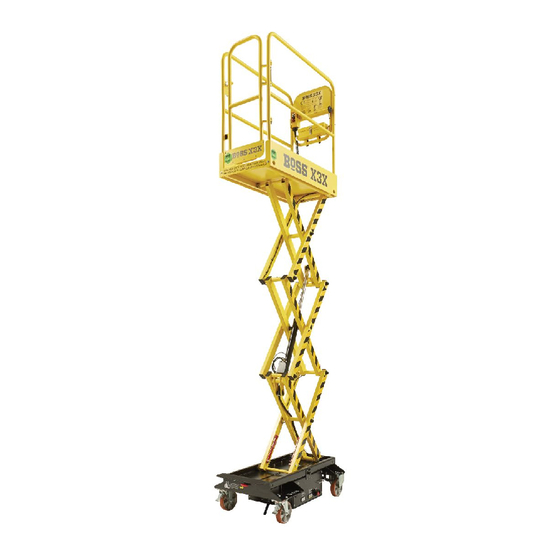
- Page 1 The ultimate range of push around micro powered access platforms MAINTENANCE MANUAL Edition December 2011 EN 280 IP24...
-
Page 2: Table Of Contents
CONTENTS SECTION 1 – DESCRIPTION, SPECIFICATION AND OPERATION PAGE Introduction Intended use Modifications Terminology Technical data Engaging the brakes Battery isolation switch Battery charging Handset control unit 1.10 Emergency lowering SECTION 2 – SAFETY DURING MAINTENANCE SECTION 3 – SERVICE ENGINEER ATTRIBUTES SECTION 4 –... -
Page 3: Section 1 - Description, Specification And Operation Page
WARNING The user must obtain the guidance and written approval of Youngman Group Ltd in the event of any special working methods or conditions which are outside those specified in this section. -
Page 4: Terminology
1.4 TERMINOLOGY Charging cables and guardrail tools tray Forklift access, hoisting and transit strap points Battery charging connection point Battery charging indicator Battery charge level indicator Base unit emergency stop Smooth roll castors with non marking tyres Step up to platform Fixed castors with auto braking applied as the platform is raised Swivel castors with click on brakes... -
Page 5: Technical Data
1.5 TECHNICAL DATA BoSS X3X BoSS X3 BoSS X2 Rated load, manual forces and weight: Safe working load 240kg equivalent to 1 person (80kg) plus 160kg tools & materials Maximum allowable manual force 200N (interior use only) Maximum allowable chassis inclination 1.25 Maximum allowable wind speed 0m/s... -
Page 6: Engaging The Brakes
1.6 ENGAGING THE BRAKES When the second segment from the left is illuminated, as shown in figure 2 below, it is time to put the BoSS X-Series machine on charge The BoSS X-Series machine is fitted with two braking systems: Fixed castors –... -
Page 7: Handset Control Unit
1.10 EMERGENCY LOWERING In the unlikely event of a power failure of the BoSS X-Series machine the platform can be lowered manually by use of the following procedure. 1.Turn the finger screw on the pressure loss valve anticlockwise until it will not turn any further as shown in figure 1. -
Page 8: Section 2 - Safety During Maintenance
SECTION 2 – SAFETY DURING SECTION 4 – COMPETENT PERSON FOR MAINTENANCE THOROUGH EXAMINATION ATTRIBUTES The competent person carrying out a thorough When carrying out maintenance on a BoSS X-Series inspection of a BoSS X-Series machine should: machine with the platform elevated, always ensure that the maintenance props are deployed as shown in the be physically fit;... -
Page 9: Section 5 - Periodical Maintenance And Checks
Replace hydraulic oil Prior to the first use of a BoSS X-Series machine all It is essential that only Youngman approved daily/pre-use checks should be undertaken. replacement parts are used when maintaining and servicing the BoSS X-Series machine. Failure to do If the BoSS X-Series machine has been out of so may result in an unsafe machine. - Page 10 Lubrication The recommended lubricant for use with the BoSS X-Series machines is standard machine grease and the lubrication points are shown in the pictures below. Scissors Figure 1 WARNING Ensure the platform is fully lowered when checking the oil level. Do not overfill the hydraulic oil reservoir and take care not to spill the oil on any of the surrounding machine components.
-
Page 11: Section 6 - Exploded Drawings And Parts List
SECTION 6 – EXPLODED DRAWINGS AND PARTS LIST BoSS X3X Assembly Item Ref Part No. Description Qty. 83901000 Guardrail assembly 81908000 Handset controller assembly 83902000 Aluminium platform and steel runner 81902014 Handle screw with locking nut 83904000 Cylinder assembly X3X youngmangroup.com... - Page 12 BoSS X3 Assembly Item Ref Part No. Description Qty. 81901001 Guardrail assembly 81908000 Handset controller assembly 81902001 Platform assembly 81902014 Handle screw with locking nut 81904000 Cylinder assembly X3 BoSS X-Series Maintenance Manual...
- Page 13 BoSS X2 Assembly Item Ref Part No. Description Qty. 82901001 Guardrail assembly 81908000 Handset controller assembly 82902001 Platform assembly 81902014 Handle screw with locking nut 82904000 Cylinder assembly X2 youngmangroup.com...
- Page 14 BoSS X3X/X3/X2 Guardrail Assembly BoSS X-Series Maintenance Manual...
- Page 15 BoSS X3X/X3/X2 Guardrail Assembly continued X3X Guardrail Assembly Item Ref Part No. Description Qty. 83801001 Right guardrail & gate assembly 83901003 Left guardrail assembly 83901007 Back guardrail assembly 81020071 Instruction tube cap 81801017 Gate hinge fixing kit 83901024 Gate toeboard with label 81020101 Gate latch 81122061...
- Page 16 BoSS X3X/X3/X2 Handset Controller Assembly Item Ref Part No. Description Qty. 81130041 Normally open switch 81130171 Normally closed switch 81130051 Main body 81130181 Front plate & back plate 81130081 Up button 81130091 Down button 81130101 Emergency stop 81801016 81130131 Waterproof cover 81020121 Curly cable assembly 81801002...
- Page 17 BoSS X3X/X3 Scissor Assembly X3X Scissor Assembly Item Ref Part No. Description Qty. 81070091 Scissor bush 81070111 Platform roller 81200151 Scissor black end cap 81903041 Maintenance prop assembly 81903039 Base roller 81070131 Caps for maintenance props 81903037 Scissor pads 83905013 X3X scissor cable X3 Scissor Assembly Item Ref...
- Page 18 BoSS X2 Scissor Assembly Item Ref Part No. Description Qty. 81070091 Scissor bush 81070111 Platform roller 81200151 Scissor black end cap 81903041 Maintenance prop assembly 81903039 Base roller 81070131 Caps for maintenance props 81903037 Scissor pads 82905003 X2 scissor cable BoSS X-Series Maintenance Manual...
- Page 19 BoSS X3X/X3 Hydraulic Cylinder Assembly BoSS X3X/X3 Hydraulic Cylinder Assembly X3X Hydraulic Cylinder Assembly Item Ref Part No. Description Qty. 81904026 Pressure loss valve cover 81904006 Pressure loss valve 81801003 Pressure loss valve o-rings 81070091 Bush 81801004 Seal kit 83904002 X3X hydraulic hose 81904031 Pressure loss valve seal kit...
- Page 20 BoSS X2 Hydraulic Cylinder Assembly BoSS X2 Hydraulic Cylinder Assembly Item Ref Part No. Description Qty. 81904026 Pressure loss valve cover 81904006 Pressure loss valve 81801003 Pressure loss valve o-rings 81070091 Bush 81801004 Seal kit 82904014 X2 hydraulic hose 81904031 Pressure loss valve seal kit BoSS X-Series Maintenance Manual...
- Page 21 BoSS X3X Base Unit Assembly Item Ref Part No. Description Qty. 81905027 Charging cables drawer knob 81905018 Charging cables drawer 81905030 Braked swivel castor 83905010 Descent cut-out limit switch 83905008 Descent cut-out switch protection plate 81905040 Charging cables drawer clip 81905039 Charging cables clip block 81905022...
- Page 22 BoSS X3/X2 Base Unit Assembly Item Ref Part No. Description Qty. 81905027 Charging cables drawer knob 81905018 Charging cables drawer 81801006 Charging cables drawer rail 81905030 Braked swivel castor 81905040 Charging cables drawer clip 81905039 Charging cables clip block 81905028 Anti static strip 81801007 Tilt sensor...
- Page 23 BoSS X3X/X3/X2 Base Unit Drawer Assembly BoSS X3X/X3 Base Unit Drawer Assembly BoSS X3X/X3 Base Unit Drawer Assembly Item Ref Part No. Description Qty. 81910043 Transparent connector cover 81801009 Relay assembly 16A 81801010 Relay assembly 5A 81801011 Timer relay assembly 81120581 Battery 100A 81907014...
- Page 24 BoSS X2 Base Unit Drawer Assembly Item Ref Part No. Description Qty. 81910043 Transparent connector cover 81801009 Relay assembly 16A 81801010 Relay assembly 5A 81801011 Timer relay assembly 82910003 Battery 80A 81907014 Battery fixing plate 82910002 Power pack 0.8kW 81801012 Pressure sensor assembly 81801013 Fuse 100A...
- Page 25 BoSS X3X/X3/X2 Power Pack Assembly Item Ref Part No. Description Qty. 81100021 Motor contactor 81100091 Solenoid & emergency release valve 81801018 O-ring 81801019 Pump youngmangroup.com...
- Page 26 BoSS X3X/X3/X2 Confined Space Guardrail Assembly (Accessory available to purchase separately) Item Ref Part No. Description Qty. 81250241 Left guardrail assembly 81250021 Back guardrail assembly 81250251 Right guardrail assembly 81250081 Top bar 81250211 Sliding bar gate fixings 81250221 Handle screws M8 81250091 Slider bar assembly 81250071...
-
Page 27: Section 7 - Electrical Schematic
SECTION 7 - ELECTRICAL SCHEMATIC youngmangroup.com... -
Page 28: Section 8 - Wiring Diagram
SECTION 8 - WIRING DIAGRAM BoSS X-Series Maintenance Manual... -
Page 29: Section 9 - Tilt Sensor
1.5°. This applies to the tilt sensor built into the machine and any replacement tilt sensor supplied by Youngman or our approved parts distributor. Should a replacement tilt sensor be fitted to the BoSS X-Series machine it must be zero calibrated (0 –... -
Page 30: Section 10 - Hydraulic Schematic
SECTION 10 - HYDRAULIC SCHEMATIC BoSS X-Series Maintenance Manual... -
Page 31: Section 11 - Machine Labelling
SECTION 11 - MACHINE LABELLING See below for the correct location of the BoSS X-Series labels and machine plate See below for the correct location of the BoSS X-Series machine labels and machine plate On all four forklift and transit strap points Located on end of the chassis CHARGING CABLES &... -
Page 32: Section 12 - Storage
SECTION 11 - MACHINE LABELLING CONTINUED Item Ref Part No. Description Qty. 83911031 X3X branding decal set 83911032 X3X safety decal set 81911031 X3 branding decal set 81911032 X3 safety decal set 82911031 X2 branding decal set 82911032 X2 safety decal set SECTION 12 - STORAGE The BoSS X-Series machine should be stored inside in a secure, clean and dry environment, the emergency stop on the handset depressed and the key removed. -
Page 33: Section 15 - Modifications To Later Boss X-Series Machines
SECTION 15 – MODIFICATIONS TO LATER BOSS X-SERIES MACHINES (REFER TO SERIAL NUMBERS AT START OF THIS SECTION) In accordance with the Youngman Group policy of This changes the EMERGENCY LOWERING procedure continuous product development we have introduced the for machines fitted with this new mechanism: following four changes to machines. - Page 34 New change BoSS X3X/X3/X2 Guardrail Assembly – showing new tool box and narrow gate BoSS X3X/X3/X2 Guardrail Assembly X3X Guardrail Assembly Item Ref Part No. Description Qty. 81200501 X-Series tool box 83801020 Right guardrail & narrow gate assembly X3 Guardrail Assembly Item Ref Part No.
- Page 35 BoSS X3X/X3 Hydraulic Cylinder Assembly – showing new pressure loss valve arrangement BoSS X3X/X3 Hydraulic Cylinder Assembly Item Ref Part No. Description Qty. 81911021 Pressure loss valve assembly – handle type 84040019 Pressure loss valve release linkage youngmangroup.com...
- Page 36 BoSS X2 Hydraulic Cylinder Assembly – showing new pressure loss valve and cover arrangement BoSS X2 Hydraulic Cylinder Assembly Item Ref Part No. Description Qty. 82904026 Pressure loss valve cover – handle type 81911021 Pressure loss valve assembly – handle type 82040019 Pressure loss valve release linkage BoSS X-Series...
- Page 37 BoSS X3X Base Unit Assembly – showing emergency pressure loss valve release handle and detachable step Item Ref Part No. Description Qty. 83911019 Detachable step 83911020 X3X emergency pressure loss valve release handle BoSS X3/X2 Base Unit Assembly – showing emergency pressure loss valve release handle BoSS X3 Item Ref Part No.
- Page 38 As a result of these machine changes four new labels have been added to the machines – see positioning in pictures below. Tool box Emergency descent procedure Charging point Emergency pressure loss valve release handle Part No. Description Qty. BoSS X3X Safety Decal Set (revised) 83911034 BoSS X3X safety decal set (revised) BoSS X3 Safety Decal Set (revised)
- Page 39 APPENDIX Report of a Thorough Examination Reference: “Lifting Operations and Lifting Equipment Regulations 1998” Regulation 10 Schedule 1 Company: Address: Site address (if different from above): Equipment Manufacturer: Serial number: Model: Year of manufacture: Date of last thorough examination: Safe working load: 6.
- Page 40 EN 280 IP24 For further information about these or any of our other products and services please contact: Youngman Group Ltd The Causeway, Maldon, Essex, CM9 4LJ, United Kingdom t +44 (0)1621 745900 f +44 (0)1621 859845 e sales@youngmangroup.com youngmangroup.com...
Need help?
Do you have a question about the BOSS X Series and is the answer not in the manual?
Questions and answers