Table of Contents
Advertisement
Advertisement
Table of Contents

Related Manuals for Nordmann Engineering Omega Series


Summary of Contents for Nordmann Engineering Omega Series
- Page 1 Nordmann Omega Steam generator OPERATION MANUAL 2590562-D EN 1901...
- Page 2 Nordmann Engineering AG, except to the extent required for installation or maintenance of recipient's equipment. Liability Notice Nordmann Engineering AG does not accept any liability due to incorrect installation or operation of the equipment or due to the use of parts/components/equipment that are not authorised by Nordmann Engineering AG. Copyright Notice ©...
-
Page 3: Table Of Contents
Contents Introduction To the very beginning Notes on the operation manual For your safety Product Overview Models overview 3.2 Identification of the unit 3.3 Construction of the Nordmann Omega steam generator 3.4 Functional description 3.5 System overview Nordmann Omega Operation 4.1 First-time commissioning Display and operating elements 4.3 Commissioning after an interruption of operation Notes on operation 4.5 Inspections during operation 4.6 Taking the unit out of operation Working with the SPA Display... - Page 4 Maintenance 7.1 Important notes on maintenance 7.2 Maintenance intervals 7.3 Maintenance list 7.4 Removing and installing components for maintenance 7.4.1 Preparing the Nordmann Omega for the removal of components 7.4.2 Removal and installation of the steam tank 7.4.3 Removal and installation of the filling cup, the level unit and the water hoses 7.4.4 Removal and installation of the drain pump 7.4.5 Removal and installation of the inlet valve 7.4.6 Removal and installation of the steam tank receptacle 7.5 Notes on cleaning the unit components 7.6 Notes on cleaning agents 7.7 Replacing the optional filter cartridge 7.8 Resetting the maintenance counter Fault elimination 8.1 Important notes on fault elimination 8.2 Fault indication 8.3 Malfunction list 8.4 Resetting the fault indication 8.5 Replacing the fuses and backup battery in the control unit Taking out of service/Disposal 9.1...
-
Page 5: Introduction
Introduction To the very beginning We thank you for having purchased the Nordmann Omega steam generator. The Nordmann Omega steam generator incorporates the latest technical ad van ces and meets all rec- ognized safety standards. Nevertheless, improper use of the Nordmann Omega steam generator may result in danger to the user or third parties and/or damage to property. - Page 6 Symbols used in this manual CAUTION! The catchword "CAUTION" used in conjunction with the caution symbol in the circle designates notes in this operation manual that, if neglected, may cause damage and/or malfunction of the unit or damage to property. WARNING! The catchword "WARNING"...
-
Page 7: For Your Safety
For your safety General Every person working with the Nordmann Omega must have read and understood the Nordmann Omega operation manual and installation manual before carrying out any work. Knowing and understanding the contents of the operation manual and installation manual is a basic requirement for protecting personnel against any kind of danger, to prevent faulty operation, and to operate the Nordmann Omega safely and correctly. - Page 8 Prohibited modifications to the unit No modifications must be undertaken on the Nordmann Omega without the express written consent of Nordmann Engineering AG. For the replacement of defective components use exclusively original accessories and spare parts available from your Nordmann representative.
-
Page 9: Product Overview
Product Overview Models overview Steam generators Nordmann Omega are available in two unit sizes with different heating voltages and steam capacities ranging from 4 kg/h up to a maximum of 20 kg/h. Model Unit size Max. steam capacity max. Heating voltage Nordmann Omega in kg/h in kW... -
Page 10: Identification Of The Unit
Identification of the unit The identification of the unit is found on the specification label: Type designation Serial number (7 digits) Month/Year Nordmann Engineering AG, Talstrasse 35-37, 8808 Pfäffikon SZ, Switzerland Heating voltage Type: Nordmann OMEGA 16 Serial No: XXXXXXX 10.18 Heating voltage: 400V/3~/50-60Hz Heating Power: 12.5 kW 26.6 A... -
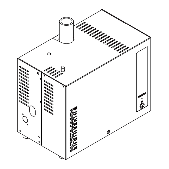
Page 11: Construction Of The Nordmann Omega Steam Generator
Construction of the Nordmann Omega steam generator 1 Water supply connector G 3/4" 16 Steam tank 2 Inlet valve 17 Coupling sleeve 3 Water supply hose 18 Level hose 4 Drain pump 19 Pump hose 5 Water drain connector ø30 mm 20 Manual drain hose 6 Water fill and drain hose 21 Unit switch... -
Page 12: Functional Description
Functional description The Nordmann Omega steam generator is an atmospheric steam generator. It operates on the resist- ance heating principle and is designed for steam generation for steam shower, steam bath, Caladarium and Rasul applications. Water supply The water is supplied via a filter valve (accessory "Z261") to the steam generator. It reaches the steam tank via the level controlled inlet valve and the open filling cup. -
Page 13: System Overview Nordmann Omega
System overview Nordmann Omega Inner diameter 30 mm (Small) / 45 mm (Medium) Z261 1 Steam generator 9 Filter valve (accessory "Z261") 2 Steam outlet connector 10 Filter cartridge (option "Size S" or "Size L") ø30 mm (Small) / ø45 mm (Medium) 11 Drain hose (by others) 3 Condensate connector ø10 mm (to drain) 12 Open funnel with water trap (by others) -
Page 14: Operation
Operation The Nordmann Omega steam generator may be commissioned and operated only by persons familiar with the Nordmann Omega steam generator and adequately qualified. It is the owner’s responsibility to verify proper qualification of the personnel. First-time commissioning The first-time commissioning must always be done by a service technician of your Nordmann repre- sentative or a well trained and authorised person of the customer. -
Page 15: Display And Operating Elements
Display and operating elements External electrical isolator(s) for voltage supply/supplies (not includ ed in the delivery, must be install ed in the mains supply lines) SPA Display (option) Reset button maintenance counter (only on units without optional SPA Display) Status LED –... -
Page 16: Commissioning After An Interruption Of Operation
Commissioning after an interruption of operation The following description outlines the start up procedure after an interruption of operation (e.g. after servicing the steam generator). It is assumed that first-time commissioning has been carried out prop- erly by the service technician of your Nordmann representative and the Nordmann Omega has been configured accordingly. -
Page 17: Notes On Operation
Notes on operation After 24 hours in standby operation (no humidity demand), the steam tank is emptied automatically. The steam tank remains empty and is not filled until a steam demand is present or the bathing operation is started manually. If, during operation, it is recognized that consistently foaming occurs in the steam tank, the carbonate hardness setting of the inlet water should be increased. -
Page 18: Taking The Unit Out Of Operation
Taking the unit out of operation In order to take the Nordmann Omega steam generator out of operation (e.g. for maintenance purpose), perform the following steps: 1. If maintenance work on the water system of the Nordmann Omega is to be carried out, the steam tank must be emptied. -
Page 19: Working With The Spa Display
Working with the SPA Display Home screens After switching on the Nordmann Omega and the automatic system test the steam generator is in normal operating mode and the Home screen is shown. The appearance of the Home screen depends on the configuration of the control software. -
Page 20: 5.1.1.2 Homescreens With Operation With "Constant Steam Production
Timer-controlled steam shower operation, the steam shower operation starts at the preset starting time or after pressing the <START> button. Warning triangle (function see chapter 5.2) Navigation elements (see chapter 5.3) Steam Shower Selected SPA application Note: With dual cabin application, you can toggle between the two applications by pressing on the SPA application field. -
Page 21: 5.1.1.3 Home Screen With Operation With "External Control
Timer-controlled steam shower operation, the steam shower operation starts at the preset starting time or after pressing the <START> button. Warning triangle (function see chapter 5.2) Navigation elements (see chapter 5.3) Steam Shower Selected SPA application Note: With dual cabin application, you can toggle between the two applications by pressing on the SPA application field. -
Page 22: Home Screens "Steam Bath Application
5.1.2 Home screens "Steam bath application" Timer functions disabled or Start option set to manual. Warning triangle (function see chapter 5.2) Navigation elements (see chapter 5.3) Selected SPA application Steam Bath Note: With dual cabin application, you can toggle between the two applications by pressing on the SPA application field. -
Page 23: Home Screens "Caldarium Application
5.1.3 Home screens "Caldarium application" Timer functions disabled or Start option set to manual. Warning triangle (function see chapter 5.2) Navigation elements (see chapter 5.3) Selected SPA application Caldarium Note: With dual cabin application, you can toggle between the two applications by pressing on the SPA application field. Current humidity in the Caldarium cabin in %. -
Page 24: Home Screens "Rasul Application
5.1.4 Home screens "Rasul application" Timer functions disabled or Start option set to manual. Warning triangle (function see chapter 5.2) Navigation elements (see chapter 5.3) Selected SPA application Rasul Note: With dual cabin application, you can toggle between the two applications by pressing on the SPA application field. Current humidity in the Rasul cabin in %. -
Page 25: Home Screens "Fin Sauna Application
5.1.5 Home screens "Fin sauna application" Timer functions disabled or Start option set to manual. Warning triangle (function see chapter 5.2) Navigation elements (see chapter 5.3) Selected SPA application Fin Sauna Note: With dual cabin application, you can toggle between the two applications by pressing on the SPA application field. -
Page 26: Function Of The Warning Triangle
Function of the warning triangle The warning triangle has the following functions: Warning triangle Description Warning triangle lights grey: The steam generator operates trouble free. Warning triangle lights yellow: A warning is present or a maintenance is due. The steam generator continues operation. However, depending on the type of warning, certain restrictions in the operation may occur. -
Page 27: Configuration Of The Control Software
Configuration of the control software 5.4.1 Accessing the main menu Press the <Menu> button on the top right corner of the display. Then, enter the password "0000" (if main menu is configured with password protection). The main menu appears. Note: The password for the user menu can be modified in the "Engineering > Admin > Password" submenu. The content of the user menu depends on the selected SPA application. - Page 28 Week Timer The programming of the week timer is equal as the day timer, however with the week timer the bathing operation is repeated. For each week day/week day range individual settings can be configured. A maximum of 10 week days/ week day ranges can be specified.
- Page 29 Rasul Times Note: This menu item only appears if the car type in the "Engineering" menu is set to "Rasul"! Setting the treatment time in minutes for the Rasul ap- Treatment Time plication User Bath Time Enter the bathing time in minutes for the Rasul application Shower Time Enter the shower time in minutes for the Rasul application Rasul Times...
- Page 30 Steam Quantity In this submenu you determine the steam production for Note: This menu item appears only steam shower operation with constant steam production. You when the steam shower mode in can select between three levels ("Low", "Mid" and "High"). the "Engineering"...
-
Page 31: Configuration Of Spa Control Software
Configuration of SPA control software The SPA control software is configured via the "Service" and the "Engineering" menu. chapter 6.1 scribes the configuration processes for the respective SPA applications. In chapter 6.2 chapter 6.3 you will find an overview of the setting parameters of the "Service" and the "Engineering" menu. Configuration processes based on the SPA application 6.1.1 Configuration procedure for steam shower application... - Page 32 Steam shower Nordmann Omega with Omega control SPA Display CAN BUS Fig. 6: Nordmann Omega with Omega control for steam shower application, operation with constant steam production...
- Page 33 Configuration procedure for steam shower application with temperature controlled or constant steam production: 1. Reset SPA Control to factory settings. (Path: Engineering > SPA Control Board > Factory Reset) 2. Important: This step must be carried out only with single cabin application: Reset SPA Display to factory settings.
- Page 34 Steam shower Nordmann Omega with Omega control SPA Display Fig. 7: Nordmann Omega with Omega control for steam shower application, operation with external demand signal...
- Page 35 Configuration procedure for steam shower application with, operation with external demand signal: 1. Reset SPA Control to factory settings. (Path: Engineering > SPA Control Board > Factory Reset) 2. Important: This step must be carried out only with single cabin application: Reset SPA Display to factory settings.
-
Page 36: Configuration Procedure For Steam Bath Application
6.1.2 Configuration procedure for steam bath application Steam bath cabin Nordmann Omega with SPA control SPA Display CAN BUS Fig. 8: Nordmann Omega with SPA Control and equippment for steam bath application... - Page 37 Configuration procedure for steam bath application: 1. Reset SPA Control to factory settings. (Path: Engineering > SPA Control Board > Factory Reset) 2. Important: This step must be carried out only with single cabin application: Reset SPA Display to factory settings. (Path: Engineering >...
-
Page 38: Configuration Procedure For Steam Bath Application With Optional Bench Heating
6.1.3 Configuration procedure for steam bath application with optional bench heating Steam bath cabin Nordmann Omega with SPA control SPA Display CAN BUS Fig. 9: Nordmann Omega with SPA Control and equippment for steam bath application with optional bench heating... - Page 39 Configuration procedure for steam bath application with optional bench heating: 1. Reset SPA Control to factory settings. (Path: Engineering > SPA Control Board > Factory Reset) 2. Important: This step must be carried out only with single cabin application: Reset SPA Display to factory settings. (Path: Engineering >...
-
Page 40: Configuration Procedure For Caldarium Application
6.1.4 Configuration procedure for Caldarium application Caldarium cabin Nordmann Omega with SPA control SPA Display CAN BUS Fig. 10: Nordmann Omega with SPA Control and equippment for Caldarium application... - Page 41 Configuration procedure for Caldarium application: 1. Reset SPA Control to factory settings. (Path: Engineering > SPA Control Board > Factory Reset) 2. Important: This step must be carried out only with single cabin application: Reset SPA Display to factory settings. (Path: Engineering >...
-
Page 42: Configuration Procedure For Rasul Application
6.1.5 Configuration procedure for Rasul application Rasul cabin Nordmann Omega wizh SPA control SPA Display Fig. 11: Nordmann Omega with SPA Control and equippment for Rasul application... - Page 43 Configuration procedure for Rasul application: 1. Reset SPA Control to factory settings. (Path: Engineering > SPA Control Board > Factory Reset) 2. Important: This step must be carried out only with single cabin application: Reset SPA Display to factory settings. (Path: Engineering >...
-
Page 44: Configuration Procedure For Dual Cabin Applications For Small Cabins
6.1.6 Configuration procedure for dual cabin applications for small cabins Fin Sauna Steam bath without bench heating Nordmann Omega 8kg/h with SPA control SPA Display CAN BUS Fig. 12: Nordmann Omega 8kg/h with SPA control for dual cabin applications for small cabins (Fin sauna and steam bath without bench heating) - Page 45 Configuration procedure for dual cabin applications for small cabins: 1. Reset SPA Control to factory settings. (Path: Engineering > SPA Control Board > Factory Reset) 2. Reset SPA Display to factory settings. (Path: Engineering > Admin > Display > Factory Reset) 3.
- Page 46 13. Determine the power consumption of the sauna heater (observe the instructions of the heater ma- nufacturer). (Path: Engineering > Sauna Heater > Heater > Heat Output) 14. Determine the temperature control settings for the Fin Sauna: (Path: Engineering > Control Settings > Temperature Control) •...
-
Page 47: Configuration Procedure For Dual Cabin Applications For Medium Size Cabins
6.1.7 Configuration procedure for dual cabin applications for medium size cabins Condair Delta SPA Control Box Fin Sauna or Bio Sauna cabin SPA Display Nordmann Omega with SPA control Steam bath, Caldarium or Rasul cabin Fig. 13: Condair Delta SPA Control Box with Nordmann Omega with SPA Control Board for dual cabin applications for medium size cabins... -
Page 48: Configuration Of Several Spa Displays
Configuration procedure for dual cabin applications for medium size cabins: 1. Reset SPA Display to factory settings. (Path: Engineering > Admin > Display > Factory Reset) 2. The menu control for the Condair Delta SPA Control Box and the Nordmann Omega must be set as follows: •... -
Page 49: Settings In The "Service" Menu
Settings in the "Service" menu Accessing the "Service" menu • Press the <Menu> button on the top right corner of the display. Then, enter the password "0000" (if main menu is configured with password protection). The main menu appears. Note: The password for the user menu can be modified in the "Engineering > Administration > Password"... - Page 50 Device Service View and reset the service values of the Nordmann Omega. – Service Done: Resetting the maintenance counter after maintenance has been carried out. – Heat Count: Shows the operating hours extrapolated to 100% steam output – Next Service: Remaining time in hours until the next maintenance is due. Filter Cartridge Display, set and reset of the filter cartridge service values.
-
Page 51: Settings In The "Engineering" Menu
Settings in the "Engineering" menu Accessing the menu "Engineering" • Press the <Menu> button on the top right corner of the display. Then, enter the password "0000" (if main menu is configured with password protection). The main menu appears. Note: The password for the user menu can be modified in the "Engineering > Administration > Password"... - Page 52 Modbus Settings Setting the Modbus parameters. – Protocessor: – Slave Address: Determining the slave address of the Protocessor. – Baudrate: Determining of the baud rate (4800, 9600, 19200, 38400, 57600, 115200) – Parity: Determining of the parity (none, 1 stop bit; none, 2 stop bit; odd, 1 stop bit; even, 1 stop bit) –...
- Page 53 Bench Temp. Control Determining of the temperature control parameters for the bench heating. Note: This menu only appears if the mode of relay 8 or relay 9 in the menu "Engineering> Accessories> Outputs" is set to "Bench Heating". – Temperature Sensor: Determining of the used temperature sensor for monitoring the bench heating (PT100, PT1000 (0.1 mA), PT1000 (1.0 mA), KTY (1.0 mA), KTY (0.1 mA)) –...
- Page 54 Keep Warm Determining of the keep warm functions. The keep-warm functions serve to keep the cabin temperature, seat temperature, etc. in standby mode at a certain value, so that the operating temperatures are reached faster in the bathing operation. Note: For steam shower application, not the cabin temperature but the water in the steam tank is kept warm.
- Page 55 Light 2 Determining of the settings for controlling Light 2. – Light Working Mode: Determining whether Light 2 is switched on and off manually ("Manual") or automatically by the SPA Control ("Auto") or whether the control of Light 2 is deactivated ("Off").
- Page 56 Determining of the settings for controlling the fans. – Fan Mode: Determining whether a single three-stage fan ("1 fan 3 Stages"), two single- stage fans ("2 fans 1-stage"), one single stage fan ("1 fan 1-stage") or no fan ("Off") is/are used.
- Page 57 Outputs Determining of the settings for controlling the additional relays 8 and 9. – Relay 8 Mode: Determining whether the additional relay 8 is activated automatically de- pendent on the corresponding states of relay 8 ("Auto Status") or whether the additional relay 8 should be used for the control of the bench heating ("bench heater") or the wall heating ("wall heater") or whether the additional relay 8 is deactivated ("Off").
- Page 58 Modbus Settings Setting the Modbus parameters. – Protocessor: – Slave Address: Determining the slave address of the Protocessor. – Baudrate: Determining of the baud rate (4800, 9600, 19200, 38400, 57600, 115200) – Parity: Determining of the parity (none, 1 stop bit; none, 2 stop bit; odd, 1 stop bit; even, 1 stop bit) –...
- Page 59 Menu Tree Cabin 1 Determining whether the settings of Cabin 1 should be displayed on the SPA display. – Enable: Display enabled ("On") or disabled ("Off"). – Server ID: Determining of the CAN BUS ID of the SPA control board or the Omega control board.
- Page 60 Output Heat Diagnostic of the heating circuits. – Heat 1: Switching the heating circuit 1 on and off. – Heat 2: Switching the heating circuit 2 on and off. – Heat 3: Switching the heating circuit 3 on and off. –...
-
Page 61: Maintenance
Maintenance Important notes on maintenance Qualification of personnel All maintenance work must be carried out only by well qualified and trained specialists authorised by the owner. It is the owner’s responsibility to verify proper qualification of the personnel. General note The instructions and details for maintenance work must be followed and upheld. -
Page 62: Maintenance Intervals
Maintenance intervals To maintain operational safety the Nordmann Omega steam generator must be maintained at regu- lar intervals. The control software of the Nordmann Omega features a maintenance counter for the unit maintenance of the steam generator and one for the Replacement of the filter cartridge (only active if system is configured for the operation with the optional filter cartridge). - Page 63 Filter cartridge replacement intervals in litres The following table gives you an overview of the approximate replacement intervals of the filter cartridge based on the specific output, the carbonate hardness of the supply water (tap water) and the size of the filter cartridge.
-
Page 64: Maintenance List
If the corresponding maintenance counter has elapsed, the yellow LED above the unit switch and on units with optional SPA Display additional the yellow warning triangle in the upper left corner of the display indicate that a maintenance must be carried out. In the fault list "Warning 29" is shown if the unit maintenance must be carried out or "Warning 165"... -
Page 65: Removing And Installing Components For Maintenance
Removing and installing components for maintenance 7.4.1 Preparing the Nordmann Omega for the removal of components Before starting any removal work set the Nordmann Omega out of operation and drain the steam tank. Please refer to the notes in chapter 4.6. 7.4.2 Removal and installation of the steam tank WARNING! - Page 66 3. Carefully lift the steam tank out of steam tank receptacle and remove it towards the front of the steam generator. CAUTION! Set down the steam tank carefully to ensure the connector on the bottom side of the steam tank is not damaged! 4.
- Page 67 5. Carefully lift off the steam tank cover with the heating elements, and remove cover sealing. CAUTION! Take care with the cover while it is removed, so as not to damage the heating elements. 6. Loosen the strainer insert and lift it out of the steam tank. o b e u n t...
- Page 68 7. If during maintenance one or more heating elements must be replaced: • First note position of the connecting cables inside the heating cable sockets. • Cut cables on the heating cable connectors. • Undo the nuts on the fixing flange of the appropriate heating element and remove heating ele- ment.
- Page 69 Assembly and installation of the steam tank Assembly of the steam tank takes place in reverse sequence of the removal. Please note the following instructions: • Installation of any heating elements which have been removed should follow the figure of step 7 the removal.
-
Page 70: Removal And Installation Of The Filling Cup, The Level Unit And The Water Hoses
7.4.3 Removal and installation of the filling cup, the level unit and the water hoses For removing the filling cup, the level unit and the water hoses the steam tank must be removed first (see chapter 7.4.2). 1. Release hose clamps, then disconnect all hoses from the corresponding connectors and remove the hoses. Note: The hoses connected to the filling cup and the level unit may also be removed together with the filling cup and the level unit (see illustration) and then disconnected from the connectors outside the unit. - Page 71 The installation of the filling cup, the level unit with control boards and the water hoses follows the re- verse sequence of the removal. Before fixing the hoses to the connectors with the hose clamps, align the hoses in a way that they are not twisted. Important: when installing the level unit make sure the two burls of the level unit engage into the holes of the third row of holes from the top.
-
Page 72: Removal And Installation Of The Drain Pump
7.4.4 Removal and installation of the drain pump For removing the drain pump the steam tank must be removed first (see chapter 7.4.2). 1. Detach electric cables (polarity of the cables must not be observed). 2. Release hose clamps and remove the hoses from the connectors. 3. -
Page 73: Removal And Installation Of The Inlet Valve
7.4.5 Removal and installation of the inlet valve For removing the inlet valve the steam tank must not be removed. 1. Detach electric cables (polarity of the cables must not be observed). 2. Release hose clamp and remove the hose from the connector. 3. -
Page 74: Removal And Installation Of The Steam Tank Receptacle
7.4.6 Removal and installation of the steam tank receptacle For removing the steam tank receptacle the steam tank must be removed first (see chapter 7.4.2). 1. Release hose clamps and remove hoses from the connectors. 2. Undo the screw fixing steam tank receptacle to the bottom of the housing with Phillips screwdriver. 3. -
Page 75: Notes On Cleaning The Unit Components
Notes on cleaning the unit components Unit component What to clean and how to clean Steam tank / steam tank strainer • Carefully knock off any limescale from the components. If the components are heavily calcified, place them in an 8% formic acid solution (observe safety notes in chapter 7.6), until the limescale comes off. - Page 76 Unit component What to clean and how to clean Inlet valve • Use a soft bristled brush (do not use a wire brush) to remove any limescale inside the inlet valve and on the strainer. • Wash inlet valve and strainer insert with a lukewarm soap solution, then rinse well with tap water.
-
Page 77: Notes On Cleaning Agents
Unit component What to clean and how to clean Level unit • Disassemble level unit. • Remove any limescale inside the housing of the level unit and its connectors using a soft bristled brush (do not use a wire brush). If the housing of the level unit is heavily calcified, place it in an 8% formic acid solution (observe safety notes in chapter 7.6), until the limescale comes off. -
Page 78: Replacing The Optional Filter Cartridge
Replacing the optional filter cartridge Note: For the replacement of the filter cartridge the water supply must not be closed since the filter head is equipped with a check valve. To replace the filter cartridge, proceed as follows 1. Switch off the Nordmann Omega via the unit switch. 2. - Page 79 8. Pace an empty container with at least 10 l capacity beside the filter cartridge and lead the open end of the bypass hose into that container. Fig. 17: Lead bypass hose into an empty container 9. Turn valve in the filter head in such a way, that "open" points to "Bypass" (flushing position, see Fig.
-
Page 80: Resetting The Maintenance Counter
Resetting the maintenance counter If the maintenance work (unit maintenance or replacement of the optional filter cartridge) has been car- ried out, the maintenance indication or maintenance counter must be reset. Proceed as follows: Resetting the maintenance counter on the Nordmann Omega without SPA Display: 1. -
Page 81: Fault Elimination
Fault elimination Important notes on fault elimination Qualification of personnel Repair work must be carried out only by qualified and well trained professionals authorised by the owner. Repair work relating to the electrical installation must be carried out by an electrician or professionals authorised by the owner. -
Page 82: Fault Indication
Fault indication Fault indication on the Nordmann Omega without SPA Display: Malfunctions during operation detected by the control software are indicated by the yellow illuminated LED (warning present or maintenance due) or the red illuminated LED (fault present) above the unit switch. -
Page 83: Malfunction List
Malfunction list Most operational malfunctions are not caused by faulty equipment but rather by improper installation or disregarding of planning guidelines. Therefore, a complete fault diagnosis always involves a thorough examination of the entire system (e.g. hose connections, control system, etc.). Warning Fault Message... - Page 84 Warning Fault Message Possible causes Remedy ––– Max. filling time Maximum filling time exceeded. Note: The operation of the Nordmann Omega is stopped. After the fault has been eliminated, the Nordmann Omega must be switched off and on again. If the Nordmann Omega is controlled by a Condair Delta SPA Control Box, the Condair Delta SPA Control Box must also be switched off and on again after the Nordmann Omega has been restarted.
- Page 85 Warning Fault Message Possible causes Remedy ––– Max. drain time Maximum drain time of the Nordmann Omega exceeded. Note: The operation of the Nordmann Omega is stopped. After the fault has been eliminated, the Nordmann Omega must be swit- ched off and on again. If the Nordmann Omega is controlled by a Condair Delta SPA Control Box, the Condair Delta SPA Control Box must also be switched off and on again after the Nordmann Omega has been restarted.
- Page 86 Warning Fault Message Possible causes Remedy ––– Local 24 V supply Local 24 V voltage on control board of the Condair Delta SPA Con- trol Box or the Nordmann Omega out of valid range. Note: The Condair Delta SPA Control Box or the Nordmann Omega goes into standby mode.
- Page 87 Warning Fault Message Possible causes Remedy ––– E155 Ext. 5 V supply External 5 V supply of the Nordmann Omega faulty. Voltage too high or too low. Note: The Condair Delta SPA Control Box or the Nordmann Ome- ga, respectively continue to work normally. Short circuit on LED.
- Page 88 Warning Fault Message Possible causes Remedy ––– E162 Heat Element 5 control relay Heating element control relay 5 does not work correctly. Note: The operation of the Condair Delta SPA Control Box or Nordmann Omega is stopped. After the fault has been eliminated, the Nordmann Omega must be switched off and on again.
- Page 89 Warning Fault Message Possible causes Remedy ––– E170 Hum. Sensor out of Range The measured humidity in the cabin is outside the permissible range. Note: The operation of the Condair Delta SPA Control Box or Nordmann Omega is stopped. After eliminating the fault, the Condair Delta SPA Control Box or the Nordmann Omega must be switched off and on again (depending on which device the fault has occurred).
- Page 90 Warning Fault Message Possible causes Remedy W175 ––– Critical Cabin Temp. The measured cabin temperature has exceeded the critical tempe- rature limit. Note: The Condair Delta SPA Control Box or the Nordmann Omega automatically disconnect all heating systems (steam, bench hea- ting, sauna heater, etc.) until the cabin temperature is within the permissible range again.
- Page 91 Warning Fault Message Possible causes Remedy ––– E181 Cntr/Demand Input The control or demand signal at the signal input is outside the valid range. Note: The operation of the Condair Delta SPA Control Box or Nordmann Omega is stopped. After eliminating the fault, the Condair Delta SPA Control Box or the Nordmann Omega must be switched off and on again (depending on which device the fault has occurred.
- Page 92 Warning Fault Message Possible causes Remedy W206 ––– Update in Progress A firmware update is running. Note: It is possible that the Condair Delta SPA Control Box or the Nordmann Omega may not work properly during the update. In addition, it is possible that the SPA display truns white during update.
-
Page 93: Resetting The Fault Indication
Warning Fault Message Possible causes Remedy W253 ––– Import Incompatible The configuration file to be downloaded is incompatible. Note: The Condair Delta SPA Control Box or the Nordmann Ome- ga, respectively continue to work normally. Some parameters in the con- Make sure that all components figuration file ("SpaExportSet- of the CAN BUS are updated... -
Page 94: Replacing The Fuses And Backup Battery In The Control Unit
Replacing the fuses and backup battery in the control unit The fuses and the backup battery on the control board must be replaced by authorized personnel only (e.g. electrician). Replace the fuses on the control board only with fuses matching the specifications below with the ap- propriate nominal current capacity. - Page 95 5. Push the swivel plate with the SPA Display upwards until in comes to a stop and remove it from the openings in the housing. Turn swivel plate 90° inwards and hang it into the corresponding openings in the housing, then push swivel plate downwards until the locking lug engages. 6.
-
Page 96: Taking Out Of Service/Disposal
Taking out of service/Disposal Taking out of service If the Nordmann Omega must be replaced or if the Nordmann Omega is not needed any more, proceed as follows: 1. Take the Nordmann Omega out of operation as described in chapter 4.6. 2. -
Page 97: Product Specification
Product specification 10.1 Performance data / Fuses "F5" voltage supply 230V/1~/50...60 Hz 400V/3~/50...60 Hz Nordmann Omega 15.3 –– –– –– –– –– 15.3 15.3 28.3 –– –– –– –– –– –– –– –– –– –– 12.0 15.3 –– –– –– –– ––... -
Page 98: Connections/Dimensions/Weights
10.3 Connections/Dimensions/Weights Nordmann Omega Water supply connector G 3/4" external thread Water drain connector ø30 mm Steam outlet connector ø29 mm ø45 mm Unit dimensions (HxBxT) 470 x 350 x 150 470 x 350 x 270 Net weight 10.6 kg 14.4 Kg Operating weight 12.9 kg... -
Page 99: Appendix
Appendix 11.1 Program descriptions SPA applications 11.1.1 Steam shower application The steam shower application is the simplest SPA application and consists only of a bathing phase. No accessories can be controlled with the steam shower application. The climate in the cabin can either be regulated to a certain temperature (up to 50 °C) or the steam is constantly fed into the cabin. -
Page 100: Caldarium Application
11.1.3 Caldarium application In the Caldarium application, the relative humidity in the cabin is around 80%, which is generated by the steam of a steam generator. The heat is mainly generated by the seat and wall heating. The operation of the Caldarium application can be divided into several phases: –... -
Page 101: Rasul Application
11.1.4 Rasul application The Rasul application is a bathing ritual originating from the ancient Arab world. In a first step, clay is applied to the skin and waited until the mass on the skin has dried out (treatment phase). Then, bathing phase follows in which the clay mass is softened by water vapor. -
Page 102: Fin Sauna Application
11.1.5 Fin sauna application In the Fin sauna application, the cabin is equipped with a sauna heater only. The cabin temperature can be regulated up to 110 °C, whereby the relative humidity is around 10%. The operation of the Fin sauna application can be divided into several phases: –... - Page 104 CH94/0002.01 Nordmann Engineering AG Lindenhofstrasse 28, 4052 Basel, Switzerland Tel. +41 61 404 46 50, Fax +41 61 404 46 79 www.nordmann-engineering.com, info@nordmann-engineering.com...
Need help?
Do you have a question about the Omega Series and is the answer not in the manual?
Questions and answers