Table of Contents
Advertisement
This document contains technology controlled for export by the U.S. Department of
Commerce in accordance with Export Administration Regulations. Diversion contrary to
Installation Guide 84464 Rev. 2
COPYRIGHT © 2017
THALES DEFENSE & SECURITY, INC.
ALL RIGHTS RESERVED
VesseLINK
Installation Guide
U.S. law prohibited.
DECEMBER 2017
JUNE 2017
JUNE 2017
JUNE 2017
i
Advertisement
Table of Contents

Related Manuals for Thales VesseLINK VF350BM


Summary of Contents for Thales VesseLINK VF350BM
- Page 1 This document contains technology controlled for export by the U.S. Department of Commerce in accordance with Export Administration Regulations. Diversion contrary to U.S. law prohibited. Installation Guide 84464 Rev. 2 COPYRIGHT © 2017 THALES DEFENSE & SECURITY, INC. ALL RIGHTS RESERVED...
-
Page 2: Installation Guide 84464 Rev
Revision History Revision History Date Revision Description Author Nov 2017 Initial release DCrossen Update – incorporation Dec 2017 of comments; added SJacques Quick Start Guide WARNING – INFORMATION SUBJECT TO EXPORT CONTROL RESTRICTIONS WARNING – INFORMATION SUBJECT TO EXPORT CONTROL RESTRICTIONS This document contains technology controlled for export by the U.S. - Page 3 The information in this document is subject to change without notice. Thales® and any other Thales trademark or Thales service mark referred to or displayed in this document are trademarks or registered trademarks of Thales.
- Page 4 Thales, or on Thales’s behalf, in the defense of any such claims or actions. SOFTWARE LICENSE The following terms govern User’s a ccess and use of the Thales - supplied software (“Software”) contained on the Product or Accessories.
- Page 5 Software and made available by Thales with the Software in any manner. USER shall use the Software solely as embedded for operation of this product. No other licenses are granted by implication, estoppel or otherwise.
-
Page 6: Table Of Contents
Table of Contents ....................1-1 INTRODUCTION & SAFETY ............................. 1-1 SAFETY .................................. 1-2 KIT CONTENTS ..............................1-4 OPTIONAL ACCESSORIES ............................. 1-4 TOOLS NEEDED FOR INSTALLATION ........................1-4 BELOW DECK UNIT (BDU) ............................ 1-6 (ADU)............................1-7 BOVE ....................2-1 MOUNTING THE ABOVE DECK UNIT (ANTENNA) ....................2-1 POLE MOUNTING (OPTIONAL) .......................... - Page 7 List of Figures 1-1: MINIMUM S ..................1-3 IGURE ISTANCE NTENNA 1-2: V LINK S ....................1-5 IGURE ESSE YSTEM WITH CCESSORIES 1-3: B (BDU) ........................1-6 IGURE ELOW 1-4: BDU F ........................1-6 IGURE RONT ANEL ETAIL 1-5: BDU B ........................
-
Page 8: Introduction & Safety
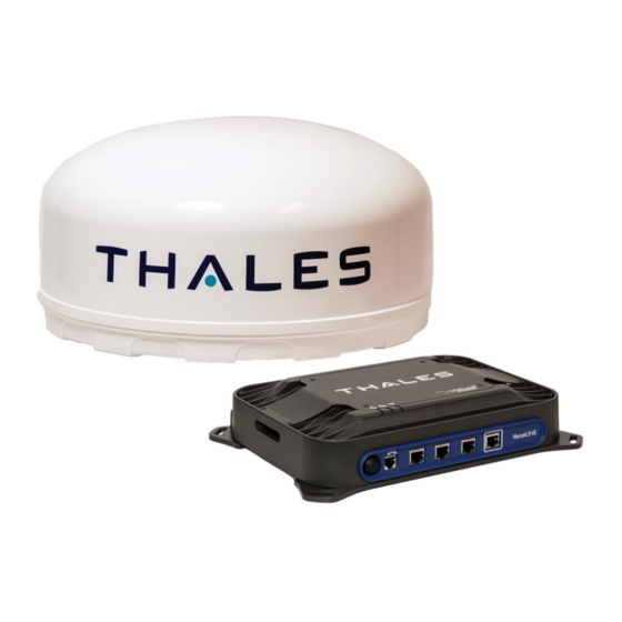
This VesseLINK system contains the Below Deck Unit (BDU), the Above Deck Unit (ADU) or antenna, an AC/DC power supply, a Wi-Fi antenna, mounting hardware and connection cables. The Thales VesseLINK product has been designed with simplicity in mind but more details may be found in the in-depth User Manual. -
Page 9: Safety
SAFETY The VesseLINK system should only be installed by a qualified professional installer of Maritime electronic systems. Improper installation could lead to system failure or could result in injury to personnel on board the vessel. The following are general safety precautions and warnings that all personnel must read and understand prior to installation, operation and maintenance of the VesseLINK system. -
Page 10: Figure 1-1: Minimum Safe Distance From Antenna
ANTENNA RADIATION HAZARDS During operation, the antenna radiates high power at microwave frequencies that can be harmful to individuals. While the unit is operating, personnel should maintain a minimum safe distance of 1.0 WARNING meters (3.3 ft.) from the antenna. The antenna should be mounted in an area that prevent the possibility of close exposure to the antenna’s radiation. -
Page 11: Kit Contents
KIT CONTENTS While unpacking the system, please verify that the following contents are included. If anything is missing, please contact Thales Customer Service at 1.800.324.6089. VesseLINK Kit VF350BM includes: Below Deck Unit (BDU) (PN 4102947-501) BAA (PN 1600901-1) ... -
Page 12: Figure 1-2: Vesselink System With Accessories
Figure 1-2: VesseLINK System with Accessories Installation Guide 84464 Rev. 2... -
Page 13: Below Deck Unit (Bdu)
BELOW DECK UNIT (BDU) Length < 12 inches (30cm) Width < 9 inches (23cm) Height < 3 Inches ( 7.6cm) Weight < 7.5 lbs (3.4kg) Figure 1-3: Below Deck Unit (BDU) The BDU front has a main power switch, one RJ-14 jack for POTS (Plain Old Telephone Service) Phone, three POE (Power over Ethernet) RJ-45 connections for VoIP phones or Ethernet, and one WAN (Wide Area Network) connection. -
Page 14: Above Deck Unit (Adu)
The BDU back panel (left to right) has a Wi-Fi antenna connector, SIM Card slot, GPIO connector, 10-32Volt DC input connector, 12Volt DC power input, antenna connector, and chassis grounding lug. Figure 1-5: BDU Back Panel Detail ABOVE DECK UNIT (ADU) The ADU (also referred to as antenna) is a standalone unit that connects to the BDU through a single coaxial cable. -
Page 15: Mounting The Above Deck Unit (Antenna)
MOUNTING THE ABOVE DECK UNIT (ANTENNA) The VesseLINK antenna is designed to fit the Thales stainless steel antenna mounting plate and many existing mounts on similar sized antennas. If replacing an existing L-band system, it may be possible to use the same mounting plate and hardware that is already in place. The VesseLINK has two sets of industry standard mounting configurations, each with four mounting points. -
Page 16: Figure 2-1: Placing Antenna For Optimum Performance
Figure 2-1: Placing Antenna for optimum performance Distance d = 2.0m for S-Band up to 50kW d = 4.0m for X & C-Bands up to 50kW Figure 2-2: Placing Antenna With Existing Radar Installation Guide 84464 Rev. 2... -
Page 17: Figure 2-3: Maritime 25 Mrf Cable Connector Detail
IMPORTANT: Antenna cable connection should be secured tightly and covered with protective rubber boot or supplied self-vulcanizing tape to prevent corrosion. It is also important to connect the antenna GND lug to Vessel Chassis GND for safety. Figure 2-3: Maritime 25m RF Cable Connector detail The antenna is mounted with either four M6 torque to 6 N*m (4.4 ft-lbs.) or four M10 torque to 28 N*m (20.6 ft-lbs.) stainless steel bolts (included with KIT #1100791-501) as appropriate for the chosen mounting pattern on the base of the antenna. -
Page 18: Pole Mounting (Optional)
001). The bracket is designed to work on standard 1.9-inch (with included bushing), 52mm and 3-inch poles (poles not included). This bracket has mounting holes that match the M6 mounting points on the bottom of the antenna. The mounting bracket can be ordered by calling Thales at 1- 800-914-0303, Option 3.”... -
Page 19: Installing The Below Deck Unit
VesseLINK can be mounted in any orientation but for best performance, it is recommended to be mounted horizontally with the Thales logo facing up. This will give the best protection against any spills or dripping water and allows for the best heat transfer. -
Page 20: Figure 2-7: Installing Sim Card And Engaging The Lock
Connect the provided Wi-Fi antenna, install the SIM Card (from service provider) into slot as shown in Figure 2-7, connect the provided AC/DC 12V power supply cable and connect the provided 25m RF cable that goes to the antenna. All connections are shown in Figure 2-8. Figure 2-7: Installing SIM Card and Engaging The Lock Figure 2-8: Wi-Fi Antenna, SIM Card, AC/DC Power Adapter and Antenna Cable Installed The BDU should be grounded. -
Page 21: Connecting Power To The Bdu
CONNECTING POWER TO THE BDU The BDU has 2 connections for direct power depending on the vessel power available: AC Operation: Supplied external AC/DC supply with power cord DC Operation for vessels operating from battery power: 10-32 Volts DC (optional DC power cable available (Part # 855024-020): o RED + ( 10-32VDC) o BLACK –... -
Page 22: Figure 2-10: 24V Dc Power Connection
Installations using the DC power cable (PN 855024-020) are recommended to connect the yellow ignition line as the primary ON/OFF source. The BDU will only turn OFF with this line, so it is important to connect to an ignition line in the fuse panel or external switch that is dedicated to the BDU for operating when the vessel’s main ignition is off. -
Page 23: Figure 2-11: 24V Dc Power Connection
Extra care and consideration must be taken when powering any device from 24V DC systems. It is important that 24V systems use the correct GND scheme that ensures unit is connected to the NOTE system’s lowest potential (usually chassis GND). Otherwise damage to the BDU and antenna are likely and could void the warranty. -
Page 24: System Status Indicators
SYSTEM STATUS INDICATORS After starting the BDU three status indicators will show on top of the unit. In Figure 2-12, from Left to Right these are: System (Overall System Status), Satellite (Satellite Connection Status) and Wi-Fi (Wireless Network Status). Figure 2-12: System Status Indicators (Top View of BDU) Table 2-1 BDU LED Status Indicator Description... -
Page 25: General Guidelines & Troubleshooting
GENERAL GUIDELINES & TROUBLESHOOTING General Guidelines for Installation It is recommended to turn on the BDU only after the antenna and all system cables have been installed and connected. Do not attempt to service items such as BDU and Antenna ... -
Page 26: Connector Details
CONNECTOR DETAILS: General Purpose Inputs / Outputs (GPIO) D-SUB 15 Pin Standard Figure 3-1 GPIO Connector Pin Detail Table 3-2: GPIO Connector Pin Definition Pin No Name Description GND1 Ground Audio_In + Radio Gateway functionality, differential (+) Hi-Z Audio Input from external Radio Audio_Out + Radio Gateway functionality, Differential (+) Low-Z Audio Output... -
Page 27: Figure 3-2 12V Input And Mating Connector Detail
BDU 12V Connection Detail Type: KPPX-4x connector (or similar) Pin 1 Figure 3-2 12V Input and Mating Connector Detail BDU 10-32VDC Connection Detail Type: 680M7W2103L201 connector (or similar) A1 = V+ /10-32VDC A2 =V- /GND Pin 5 = Ignition Pin 1 Figure 3-3 10-32 VDC and Mating Connector Detail Installation Guide 84464 Rev. -
Page 28: Declaration Of Conformity
DECLARATION OF CONFORMITY Contact your Thales representative for a copy of the FCC Compliance statement Installation Guide 84464 Rev. 2... -
Page 29: Vesselink Quick Start Guide (Pn 3402131-1)
VESSELINK QUICK START GUIDE (PN 3402131-1) Installation Guide 84464 Rev. 2... - Page 30 The BDU can accept up to 2 POTS phones (with RJ-14 Splitter). VoIP or Thales IP Phone connection By default the BDU has (3) lines preconfigured for use with the Thales IP handsets. If using a VoIP phone, Thales recommends CISCO SPA504G and Grand Stream GXP2140 models for ease of use with VesseLINK.
- Page 31 At this time it is advised that all users change your username and password. To Change Password: Go to Settings-->General and change the password for the Admin User When you first log into the Thales Management Portal, you will notice on the left hand side of Option B: Via (PC, Mac or Linux) Ethernet connection the screen.
- Page 32 Thales Defense & Security, Inc. 22605 Gateway Center Drive | Clarksburg MD 20871 Toll-Free 1.800.324.6089 | Phone: 240.864.7000 | Fax: 240.864.7920 Email: Customer.Service@thalesdsi.com | Website: www.thalesdsi.com...
Need help?
Do you have a question about the VesseLINK VF350BM and is the answer not in the manual?
Questions and answers