
Summary of Contents for Horstmann ComPass B
- Page 1 Dipl.-Ing. H. Horstmann GmbH Humboldtstraße 2 42579 Heiligenhaus www.horstmanngmbh.com Instructions for Use ComPass B 4023841-001 June 2011...
-
Page 2: Table Of Contents
Electrical connection 4.4.1. Terminal strips 4.4.2. Assignment of terminal strips Device configuration and commissioning 5.1. Device configuration 5.2. Voltage calibration 5.3. Commissioning Technical Data Appendix A: Parametrization ComPass B 19-23 Appendix B: Menu Configuration ComPass B 24-29 ComPass B 4023841-001... - Page 3 Dipl.-Ing. H. Horstmann GmbH Instructions for Use General Information! Before installing and operating this instrument carefully read and understand the contents of this manual. The content of this operating manual reflects the current state of the art at the date of printing. We reserve the right to make technical changes at any time and without prior notice as necessary in the framework of ongoing developments.
-
Page 4: Intended Use
Dipl.-Ing. H. Horstmann GmbH Instructions for Use Intended Use The ComPass B is used in medium-voltage distribution networks and combines the functions of a directional short-circuit and directional earth fault indicator. It has been developed and designed • to detect short-circuits and earth faults •... -
Page 5: Hr-Interface Cable Set
VDE 0682 Part 415 standard (IEC 61243-5) for capacitive voltage detecting systems. Besides their main function, WEGA 1.2 C and WEGA 2.2 C, respectively, can provide the tapped capacitive voltage to the ComPass B in order to measure and detect the fault direction and load flow. -
Page 6: Device Functions
The instrument measures permanently the phase voltages and currents taking these values as a basis for real time calculations of the neutral point displacement voltage V and earth fault current Based on these values the ComPass B is able to detect faults in medium-voltage networks and also to determine their characteristics. Figure 9:... -
Page 7: Fault Direction
In some cases it is not possible to determine the direction of a fault, especially when the fault is located close to the switchgear unit the ComPass B is installed into. In such cases the ComPass B signals an error without directional indication. -
Page 8: Voltage Ring Buffer
If there is a small distance between the location of the fault and the place of installation of the ComPass B unit, the phase voltages of the affected phases may become too small to be usefull for the decision of fault direction. For this reason, the Compass B is provided with a ring buffer. The measured values of all phase voltages are permanently written into this buffer. -
Page 9: Reset Modes
If a relay is configured for momentary contact it will engage for 1s for every fault assigned to it, whereas, if it is configured for permanent contact, it will remain engaged as long as ComPass B is indicating the fault. If a second fault occurs, it will disengage for 1s and then re-engage. -
Page 10: Operator Control
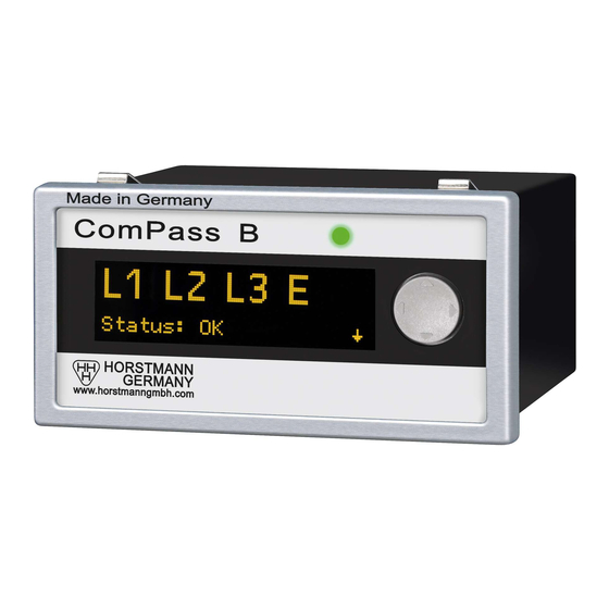
Multicolour LED The multicolour LEDs signal different operating conditions of the ComPass B (see Table 1). In par- ticular when the OLED display is not illuminated, the LED gives advanced information that can be investigated in more detail by the user via the OLED display. -
Page 11: Power Supply
The ComPass B is a MODBUS Remote Terminal Unit (RTU) Slave. 3.3.3. Digital inputs/outputs The ComPass B is provided with 4 digital (relay) outputs and one digital input. Each relay output can be assigned with individual functionality either via the front panel control or the RS485/MOD- BUS interface. -
Page 12: Test Mode
• external input contact During test mode, the ComPass B controls both its electronics and its software. The yellow light of the multicolour LED starts flashing to indicate the test mode. If an error is detected on the device, the multicolour LED flashes yellow, either in a double or triple flash mode which depends on the type of error. - Page 13 Dipl.-Ing. H. Horstmann GmbH Instructions for Use Figure 18: Installation of current transformers 4.3.2. Installation of single-phase current transformers Install each CT as to ensure that the arrow and the "↓B" show towards the bottom of the switchgear. Figure 19: Direction indication "↓B"...
-
Page 14: Terminal Strips 1
Dipl.-Ing. H. Horstmann GmbH Instructions for Use 4.4. Electrical connection 4.4.1. Terminal strips The terminal strips are located in the rear wall of the instrument. If provided on the side of the switchgear, perform electrical connection according to the following terminal reference list (See also circuit diagram on the top side of the instrument, numerical arrangement from right to left). -
Page 15: Device Configuration And Commissioning
5.1. Device configuration ComPass B is delivered with a standard factory setting (see Appendix A) which, in most cases, meets all requirements. Some parameters (see Table 5) however need to be set and checked indi- vidually which can be carried out either via the front panel control or the RS485/MODBUS interface. -
Page 16: Voltage Calibration
5.2. Voltage calibration Step 1: Voltage calibration is required after ComPass B has been installed in the switch-gear and the switch-gear has been energised. Below voltage calibration is carried out using the example of a 11 kV network. Step 2: Voltage calibration is possible only, if medium voltage is applied to the switch-gear. - Page 17 Dipl.-Ing. H. Horstmann GmbH Instructions for Use Step 4: ComPass B menu settings for voltage calibration Select menu: Settings →↓ Expert Mode →↓ Grid parameter - Set frequency to 50 Hz - Set VNom to 11.0 kV (Voltage used in this example !) Select menu: Settings →↓...
-
Page 18: Commissioning
Instructions for Use 5.3. Commissioning The ComPass B is ready for operation after the following works have been completed: “Installation” according to section 4, “Device configuration” according to section 5.1 and “Voltage calibration” ac- cording to section 5.2. Technical Data... - Page 19 Dipl.-Ing. H. Horstmann GmbH Instructions for Use External input for connection of a potential-free contact, configurable function Digital outputs 4 relays NC/NO Permanent contact/momentary contact (1 s) Contact capacity: 230 V AC/1 A/62.5 VA max. 220 V DC/1 A/60 W max.
-
Page 20: Appendix A: Parametrization Compass B
Dipl.-Ing. H. Horstmann GmbH Instructions for Use Appendix A: Parameterization ComPass B For unambiguous assignment of the device transfer your serial number (see sticker top panel): S.No......Settings Assignment Asjustment Default Customer setting Basic setting I>> Short-circuit trip current... - Page 21 Dipl.-Ing. H. Horstmann GmbH Instructions for Use Settings Assignment Asjustment Default Customer setting Relay responds to earth Adjustable for IE> faults (non-directional) each relay Relay responds to earth fault Adjustable for IE> A direction A each relay Relay responds to earth fault Adjustable for IE>...
- Page 22 Dipl.-Ing. H. Horstmann GmbH Instructions for Use Settings Assignment Asjustment Default Customer setting Relay 3 Relay operates at: Type Mode Momentary • fault (all) B direction „forward“ I>> I>> A • Common message for I>> B all phases L1, L2, L3 IE>...
- Page 23 Blinde angle in wattmetric 2°-20° 10° earth fault detection DatFormat Size of the timestamp Abs (Absolut) Rel (Relativ) ComPass Device funtionality: A (ComPass A) B (ComPass B) ComPass B works as B (ComPass B) ComPass A Sicherheit Pin activation 0-9999 ComPass B 4023841-001...
-
Page 24: Appendix B: Menu Configuration Compass B
Dipl.-Ing. H. Horstmann GmbH Instructions for Use Appendix B: Menu configuration ComPass B ComPass B 4023841-001... - Page 25 Dipl.-Ing. H. Horstmann GmbH Instructions for Use ComPass B 4023841-001...
- Page 26 Dipl.-Ing. H. Horstmann GmbH Instructions for Use ComPass B 4023841-001...
- Page 27 Dipl.-Ing. H. Horstmann GmbH Instructions for Use ComPass B 4023841-001...
- Page 28 Dipl.-Ing. H. Horstmann GmbH Instructions for Use ComPass B 4023841-001...
- Page 29 Dipl.-Ing. H. Horstmann GmbH Instructions for Use ComPass B 4023841-001...
Need help?
Do you have a question about the ComPass B and is the answer not in the manual?
Questions and answers