
Related Manuals for AnaPico APSIN Series


Summary of Contents for AnaPico APSIN Series
- Page 1 User’s Manual V3.01 Signal Source Models APSIN, APSYN, APGEN, APMS, APULN User’s Manual – Signal Source Models – v3.01 September 2019 AnaPico Ltd. - www.anapico.com – sales@anapico.com...
- Page 2 All AnaPico instruments are warranted against defects in material and workmanship for a period of two years from the date of shipment. AnaPico will, at its option, repair or replace products that prove to be defective during the warranty period, provided they are returned to AnaPico and provided the preventative maintenance procedures are followed.
-
Page 3: Table Of Contents
) ..................22 ENERAL EATURES AND UNCTIONS ODEL OVERVIEW ................................23 PTIONS GETTING STARTED ..............................24 ............................24 YSTEM EQUIREMENTS ..........................24 NPACKING THE NSTRUMENT Page 2 – Signal Source Models – v3.01 September 2019 AnaPico Ltd. - www.anapico.com – sales@anapico.com... - Page 4 ....................F ONTROL EHLER EXTMARKE NICHT DEFINIERT GUI C ..........................30 ULTI UTPUT ONTROL ............................30 OMBINED ODULATION LOCAL OPERATION VIA FRONT PANEL ......................... 32 Page 3 – Signal Source Models – v3.01 September 2019 AnaPico Ltd. - www.anapico.com – sales@anapico.com...
- Page 5 MAINTENANCE AND WARRANTY INFORMATION....................43 ........................... 43 DJUSTMENTS AND ALIBRATION ................................43 EPAIR ............................ 43 ARRANTY NFORMATION ............................43 QUIPMENT ETURNS APPENDIX A ................................44 Page 4 – Signal Source Models – v3.01 September 2019 AnaPico Ltd. - www.anapico.com – sales@anapico.com...
-
Page 6: General Remarks
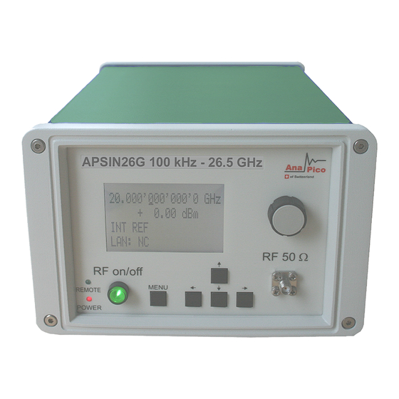
Figure 1: APSIN26G & APULN40 in a Compact Portable Case (with LCD and touch display, respectively) 1U Rackmount (1URM) Figure 2: APSIN26G in a 1URM Case Page 5 – Signal Source Models – v3.01 September 2019 AnaPico Ltd. - www.anapico.com – sales@anapico.com... -
Page 7: Case (1Urm)
1U Case (1URM) Figure 3: APSMXXG-4 (and APSYN140-4) in a 1URM case Desktop Case (LH) Figure 4: APSIN/APULN in a Desktop Case Page 6 – Signal Source Models – v3.01 September 2019 AnaPico Ltd. - www.anapico.com – sales@anapico.com... -
Page 8: Data Connections
The devices must only be transported with the packaging supplied by the manufacturer. The device can be lifted up or transported in any orientation. Page 7 – Signal Source Models – v3.01 September 2019 AnaPico Ltd. - www.anapico.com – sales@anapico.com... -
Page 9: Safety Information
Earth (Ground) EU label for separate collection of electrical and electronic waste. Caution, general danger zone. Attend the manual and/or a notice on the device. Page 8 – Signal Source Models – v3.01 September 2019 AnaPico Ltd. - www.anapico.com – sales@anapico.com... -
Page 10: General Safety Considerations
For this reason, the product may only be disassembled or opened by specially trained personnel. Improper disassembly may be hazardous to your health. National waste disposal regulations must be observed. Page 9 – Signal Source Models – v3.01 September 2019 AnaPico Ltd. - www.anapico.com – sales@anapico.com... -
Page 11: Technical Specifications
The front panel contains a status display (only in CPC), RF output female N-type connector (APSINX010), a female SMA connector (APSINXXG, APULN06,12,20,26, APMSXXG, APSYN), or a K connector (APULN40) and an Page 10 – Signal Source Models – v3.01 September 2019 AnaPico Ltd. - www.anapico.com – sales@anapico.com... - Page 12 The power LED is indicating whether the device is on or off. Remote LED The remote LED is indicating whether the device connected to a Computer or not. Page 11 – Signal Source Models – v3.01 September 2019 AnaPico Ltd. - www.anapico.com – sales@anapico.com...
- Page 13 Fan Holes The holes by which the air is intake. Power Supply apply the AnaPico power adaptor to this connector to supply the device with energy. ON/OFF Switch Turns the device on or off. Ground Screw FUNC OUT This BNC female Connector is the output for the function signal.
-
Page 14: 1Urm
This BNC female Connector is the input for the reference signal. REF OUT This BNC female Connector is the output for the reference signal. Page 13 – Signal Source Models – v3.01 September 2019 AnaPico Ltd. - www.anapico.com – sales@anapico.com... - Page 15 The maximum allowed DC level is +/- 10 V. Please check the data sheets for more details. Channel 2 Channel 3 Channel 4 Rear Panel Page 14 – Signal Source Models – v3.01 September 2019 AnaPico Ltd. - www.anapico.com – sales@anapico.com...
-
Page 16: Cpc With Touchdisplay
APMSXXG, APSYN), or a K connector (APULN40). The touch display shows information on the current function. Information includes status indicators, frequency and amplitude settings, current connectivity status, and error messages. Front panel Page 15 – Signal Source Models – v3.01 September 2019 AnaPico Ltd. - www.anapico.com – sales@anapico.com... - Page 17 The LAN connector is used to connect the device to a network. Fan Holes The holes by which the air is intake. Power Supply apply the AnaPico power adaptor to this connector to supply the device with energy. ON/OFF Switch Turns the device on or off. Ground Screw TRIG OUT This BNC female Connector is a multi-function output.
-
Page 18: Desktop
The impedance is 50 ohm. The reverse power damage level is +30 dBm maximum allowed DC level please check the data sheet. Please check the data sheets for more details. Page 17 – Signal Source Models – v3.01 September 2019 AnaPico Ltd. - www.anapico.com – sales@anapico.com... -
Page 19: Minimum Distances
The USB B connector is used to connect the device to a computer. The LAN connector is used to connect the device to a network. Power Supply apply the AnaPico power adaptor to this connector to supply the device with energy. ON/OFF Switch Turns the device on or off. -
Page 20: Energizing And De- Energizing
B: 1mm C: 50 mm D: 50 mm Energizing and de- Energizing To energize the device, apply the following voltage to the following connector. Page 19 – Signal Source Models – v3.01 September 2019 AnaPico Ltd. - www.anapico.com – sales@anapico.com... - Page 21 Type of fuse: Size: 5 x 20 mm Voltage: 250V ~ Current rating: 3.15A Characteristic: Time-Lag T Breaking capacity: 35A – 200A Page 20 – Signal Source Models – v3.01 September 2019 AnaPico Ltd. - www.anapico.com – sales@anapico.com...
-
Page 22: Proper Operation Conditions
Environmental Information 1. Waste electrical and electronic equipment must not be disposed of with unsorted municipal waste, but must be collected separately. Contact the Anapico customer service center for environmentally responsible disposal of the product. 2. Specially marked equipment has a battery or accumulator that must not be disposed of with unsorted municipal waste, but must be collected separately. -
Page 23: Introduction
Introduction This instruction manual is valid for AnaPico model series APSIN, APULN, APMS and APSYN. Chapter gives guidance for a quick and easy setup of your new instrument. Chapter describes the remote operation via AnaPico graphical user interface (GUI). Chapter describes control via front panel and applies only to APSIN models. -
Page 24: Options
LH: Desktop housing with color touch-screen front panel NM: Remove modulation function EB: External power bank PHS: Phase coherent switching VREF: Variable external reference Page 23 – Signal Source Models – v3.01 September 2019 AnaPico Ltd. - www.anapico.com – sales@anapico.com... -
Page 25: Getting Started
Getting Started System Requirements The AnaPico graphical user interface requires at least the minimum system requirements to run one of the supported operating systems. Operating system Windows™ 2000 SP4, XP SP2, Vista, 7, 8, 10 Remote 10/100/1000M Ethernet or USB 2.0 Port Unpacking the Instrument Remove the instrument materials from the shipping containers. -
Page 26: Direct Connectivity To Host Via Ethernet Cable (No Router)
USBTMC device. Note if you want to work with the AnaPico GUI, it must be installed with USB support selected. Then the GUI will detect all attached devices automatically. Open the GUI and follow the instructions given in Chapter Alternatively, a VISA runtime environment (NI, Keysight or comparable) must be installed. -
Page 27: Shutting Down The Signal Generator
When Microsoft .NET Framework is not installed make sure that your computer is connected to the • internet during installation of the AnaPico Software. If no internet connection is available, install the .NET™ Framework that is available on the installation CD. -
Page 28: Using The Graphical User Interface (Gui)
Using the Graphical User Interface (GUI) AnaPico’s graphical user interface provides an intuitive control of the signal generator. It runs under any Windows™ operating system. Make sure the software is installed correctly and the computer’s firewall is configured properly. The GUI’s dynamic link library (DLL) uses the Microsoft .NET framework. -
Page 29: Simultaneously Controlling Multiple Signal Generators From One Pc
Simultaneously controlling Multiple Signal Generators from one PC You can easily control multiple AnaPico instruments from a single computer but you need to start a separate GUI for every instrument as only one instrument is controlled by the GUI at once. -
Page 30: Setting Network Configuration
(.tar) ready. Then apply Controller Update Firmware and select the appropriate binary file that you have received from AnaPico or downloaded from the AnaPico website. The update will take a few seconds and after completion your instrument will reboot. -
Page 31: Multi -Output Gui Control
Multi-Output GUI Control Individual outputs of the AnaPico multi-channel signal sources (such as APMSXXG-X or APSYN140-X) can be controlled by the GUI by selecting the corresponding channel above the control tab menu. Each channel can be configured fully independently as if they were individual signal generators. Note that the "Select Channel"... - Page 32 EXTERNAL YES / YES YES / YES INTERNAL NO/ NO EXTERNAL NO/ NO PULSE INTERNAL EXTERNAL LF Generator CHIRP NO/NO YES/YES YES/YES Table 6-e Page 31 – Signal Source Models – v3.01 September 2019 AnaPico Ltd. - www.anapico.com – sales@anapico.com...
-
Page 33: Local Operation Via Front Panel
This is a multifunction key. The key is used to enter and exit menus. Press once to return to CW menu, press multiple times to toggle between the currently selected submenu and the CW menu. Page 32 – Signal Source Models – v3.01 September 2019 AnaPico Ltd. - www.anapico.com – sales@anapico.com... -
Page 34: Displayed Parameter Formats
The Main or CW Display is shown after the instrument has successfully booted and is ready. The four line display has the following format: Output Frequency Output Power Ref. Frequency Remote Control Page 33 – Signal Source Models – v3.01 September 2019 AnaPico Ltd. - www.anapico.com – sales@anapico.com... -
Page 35: Main Menu Display
INFinite and 1 (single repetition). RF On/Off button. Start the sweep by pressing the Number of Points per Sweep On (dwell) time Off time Page 34 – Signal Source Models – v3.01 September 2019 AnaPico Ltd. - www.anapico.com – sales@anapico.com... -
Page 36: Power Sweep Submenu
Start the sweep by pressing the RF On/Off button. List Sweep Submenu When entering the List Sweep submenu, a list of stored list sweeps is displayed. Page 35 – Signal Source Models – v3.01 September 2019 AnaPico Ltd. - www.anapico.com – sales@anapico.com... -
Page 37: Modulation Submenu
In the phase modulation submenu the internal and external phase modulation can be accessed. It is possible to change between internal and external modulation source and change modulation parameters Page 36 – Signal Source Models – v3.01 September 2019 AnaPico Ltd. - www.anapico.com – sales@anapico.com... -
Page 38: Reference Submenu
TRIG to enable the instrument trigger output and PULM to enable the pulse video output. If LFG is selected, select the waveform between sine, triangle, or square. Then enter the desired output frequency and voltage amplitude. Page 37 – Signal Source Models – v3.01 September 2019 AnaPico Ltd. - www.anapico.com – sales@anapico.com... -
Page 39: Lan Configuration Submenu
RF ON/OFF key button to load. Figure 7-s Restore Startup Settings Help Submenu This submenu provides basic information about the front panel menu control. Page 38 – Signal Source Models – v3.01 September 2019 AnaPico Ltd. - www.anapico.com – sales@anapico.com... -
Page 40: Remote Programming The Signal Generator
Remote Programming the Signal Generator The signal generator can be remotely programmed. Please refer to the Programmer’s Manual for details. Page 39 – Signal Source Models – v3.01 September 2019 AnaPico Ltd. - www.anapico.com – sales@anapico.com... -
Page 41: Battery Operation (B3 Option)
During operation the approximate remaining battery capacity is indicated by the battery symbol visible in the upper right corner of the display (see Figure 9-a) Page 40 – Signal Source Models – v3.01 September 2019 AnaPico Ltd. - www.anapico.com – sales@anapico.com... - Page 42 OFF position. After storage, first charge the unit for 4-6 hours. To replace the battery at the end of its lifetime, please contact AnaPico or one of its distributors. NOTE: ♦...
-
Page 43: Extended Power Range (Pe3 Options)
With these options PE3 installed, a mechanical step attenuator module is added. For the guaranteed minimum power level, please consult the respective datasheet. In sweeps where the mechanical attenuator is switched, the minimum dwell time increases to 20 ms. Page 42 – Signal Source Models – v3.01 September 2019 AnaPico Ltd. - www.anapico.com – sales@anapico.com... -
Page 44: Maintenance And Warranty Information
All AnaPico instruments are warranted against defects in material and workmanship for a period of two years from the date of shipment. AnaPico will, at its option, repair or replace products that prove to be defective during the warranty period, provided they are returned to AnaPico and provided the preventative maintenance procedures are followed. - Page 45 Appendix A Page 44 – Signal Source Models – v3.01 September 2019 AnaPico Ltd. - www.anapico.com – sales@anapico.com...
- Page 46 Page 45 – Signal Source Models – v3.01 September 2019 AnaPico Ltd. - www.anapico.com – sales@anapico.com...
- Page 47 AnaPico Ltd. of Switzerland Phone +41 44 515 55 01 www.anapico.com Europastrasse 9 +41 44 440 00 50 www.anapico.com/downloads/ 8152 Glattbrugg Email sales@anapico.com Switzerland Page 46 – Signal Source Models – v3.01 September 2019 AnaPico Ltd. - www.anapico.com – sales@anapico.com...
- Page 48 NOTES Page 47 – Signal Source Models – v3.01 September 2019 AnaPico Ltd. - www.anapico.com – sales@anapico.com...
Need help?
Do you have a question about the APSIN Series and is the answer not in the manual?
Questions and answers