
Related Manuals for AnaPico APSIN Series


Summary of Contents for AnaPico APSIN Series
- Page 1 User’s Manual V1.41 Signal Generator Models APSIN, APGEN, APSYN Anapico AG Europastr. 9 CH-8152 Glattbrugg Switzerland Tel: +41 44 515 5501 www..anapico.com...
- Page 2 All Anapico instruments are warranted against defects in material and workmanship for a period of two years from the date of shipment. AnaPico will, at its option, repair or replace products that prove to be defective during the warranty period, provided they are returned to Anapico and provided the preventative maintenance procedures are followed.
-
Page 3: Table Of Contents
LF OUT C ..........................30 ONTROL 3.11 ........................32 OMBINED ODULATION LOCAL OPERATION VIA FRONT PANEL ....................33 ........................34 ISPLAYED ARAMETER ORMATS CW D ............................... 34 ISPLAY Anapico AG Europastr. 9 CH-8152 Glattbrugg Switzerland Tel: +41 44 515 5501 www..anapico.com... - Page 4 EXTENDED POWER RANGE (PE3 OPTIONS) .................... 52 MAINTENANCE AND WARRANTY INFORMATION .................. 53 ........................53 DJUSTMENTS AND ALIBRATION ..............................53 EPAIR ..............................53 AFETY ..........................53 ARRANTY NFORMATION ..........................54 QUIPMENT ETURNS Anapico AG Europastr. 9 CH-8152 Glattbrugg Switzerland Tel: +41 44 515 5501 www..anapico.com...
-
Page 5: Introduction
1 Introduction This instruction manual is valid for Anapico model series APSIN, APGEN, and APSYN. Chapter 2 gives you guidance for a quick and easy setup of your new instrument. Chapter 3 describes the remote operation via Anapico graphical user interface (GUI). Chapter 4 describes control via front panel and applies only to APSIN models. -
Page 6: Options
• Long-term support: Software upgrades (firmware, API, GUI) are available to download from www.anapico.com . You can also call our technical specialists for support. You can continue to use both of these services free of charge for the lifetime of the product. -
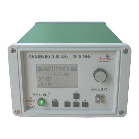
Page 7: Front Panel Overview (Apsin Models Only)
The main display shows the following information: line: RF frequency in Hz line: RF amplitude in dBm line: Frequency reference status (internal, external, lock status) line: Remote control status Anapico AG Europastr. 9 CH-8152 Glattbrugg Switzerland Tel: +41 44 515 5501... -
Page 8: Rear Panel Connections
9 FUNCT OUT connector Female BNC connector is used as a multiple purpose output. It can be programmed as trigger output, as video output during pulse modulation and as output for the low frequency function generator. Anapico AG Europastr. 9 CH-8152 Glattbrugg Switzerland Tel: +41 44 515 5501 www..anapico.com... - Page 9 OCXO warming up and RF out switched off. The red power LED on the front panel is turned on. 11 DC IN power receptacle The power receptacle accepts two-pin plug from the external 6 V DC power adapter. Anapico AG Europastr. 9 CH-8152 Glattbrugg Switzerland Tel: +41 44 515 5501...
-
Page 10: Getting Started
2 Getting Started 2.1 System Requirements The Anapico graphical user interface requires at least the minimum system requirements to run one of the supported operating systems. Operating system Windows™ 2000 SP4, XP SP2, Vista, 7, 8 Remote 10/100/1000M Ethernet or USB 2.0 Port 2.2 Unpacking the Instrument... -
Page 11: Connecting To Lan
USBTMC device. Note if you want to work with the Anapico GUI, it must be installed with USB support selected. Then the GUI will detect all attached devices automatically. Open the GUI and follow the instructions given in Chapter 4. -
Page 12: Troubleshooting The Lan Interconnection
When Microsoft .NET Framework is not installed make sure that your computer is connected to the internet during installation of the Anapico Software. If no internet connection is available, install the .NET™ Framework that is available on the installation CD. -
Page 13: Using The Graphical User Interface (Gui)
3 Using the Graphical User Interface (GUI) Anapico’s graphical user interface provides an intuitive control of the signal generator. It runs under any Windows™ operating system. Make sure the software is installed correctly and the computer’s firewall is configured properly. The GUI’s dynamic link library (DLL) uses the Microsoft .NET framework. -
Page 14: Simultaneously Controlling Multiple Signal Generators From One Pc
3.2.1 Simultaneously controlling Multiple Signal Generators from one PC You can easily control multiple Anapico instruments from a single computer but you need to start a separate GUI for every instrument as only one instrument is controlled by the GUI at once. -
Page 15: Store And Load Instrument States
Using a DHCP (dynamic host configuration protocol) server can be enabled or a static IP can be entered by user. The device name can be modified as desired. The unit serial number and firmware revision are displayed on the bottom. Anapico AG Europastr. 9 CH-8152 Glattbrugg... -
Page 16: Setting The Gpib Address
Update Firmware and select the appropriate binary file that you have received from Anapico or downloaded from the Anapico website. The update will take a few seconds and after completion your instrument will reboot. Reconnect to the instruments after booting is completed and continue with the updated firmware. -
Page 17: Basic Cw Operation (Cw Tab)
Reset System Restart Controller 3.5 Basic CW Operation (CW tab) Anapico signal generators are laboratory instruments designed to generate a synthesized CW signal with good spectral purity and fixed or variable amplitude. To set a desired frequency, relative phase Figure 3-d and amplitude, click to the CW tab ( ). -
Page 18: Frequency Sweep
This mode sweeps logarithmically from start to stop frequency in a given number of points per decade. 3.6.1.3 Frequency Random Sweep The output frequency is selected randomly between start and stop frequency. The number of different output frequencies is determined by the number of points selected by the user. Anapico AG Europastr. 9 CH-8152 Glattbrugg Switzerland Tel: +41 44 515 5501 www..anapico.com... -
Page 19: Power Sweep
ALC mode: on, hold or off. Generally ALC on is used. If very short dwell times (< 2 ms) are needed, the ALC can be set to “hold”. This way the ALC loop is disabled during the Anapico AG Europastr. 9... - Page 20 Microsoft Excel. Each line describes one list point. The first line must contain all for entries, in any other line entries may be omitted. Lists may contain up to 10’000 lines. Anapico AG Europastr. 9 CH-8152 Glattbrugg...
- Page 21 List sweeps can be directly loaded, edited and saved from the GUI. Press the List Memory button in the List Sweep Tab to open the list sweep editor as shown in Figure 3-i. Figure 3-g LIST SWEEP Tab Anapico AG Europastr. 9 CH-8152 Glattbrugg...
- Page 22 The list sweep that shall be executed must be loaded into the Device list RAM by using the Send or ↑Load buttons. Confirm your selection with “OK” to return to the List Sweep Tab and start the sweep with ON/OFF button. Anapico AG Europastr. 9 CH-8152 Glattbrugg Switzerland Tel: +41 44 515 5501...
- Page 23 Figure 3-i List Editor Anapico AG Europastr. 9 CH-8152 Glattbrugg Switzerland Tel: +41 44 515 5501 www..anapico.com...
-
Page 24: Modulation Control
For external modulation change the “Source” to “External Pulse”. For both, internal and external, the “Inverse Polarity” button allows the instant inversion of the modulation polarity. Figure 3-j PULSE Tab Anapico AG Europastr. 9 CH-8152 Glattbrugg Switzerland Tel: +41 44 515 5501... -
Page 25: Pulse Train Modulation
The pulse width and pulse period can be set in ranges of milliseconds or microseconds and selected Figure 3-j by the button next to the digits ( Figure 3-k Editor for Pulse Trains Anapico AG Europastr. 9 CH-8152 Glattbrugg Switzerland Tel: +41 44 515 5501 www..anapico.com... -
Page 26: Amplitude Modulation
For external angle modulation, enter the desired sensitivity per Volt for either frequency or phase modulation and press the ON/OFF button to enable (disable) the modulation. Connect the modulation source to the rear BNC input. Anapico AG Europastr. 9 CH-8152 Glattbrugg... -
Page 27: Chirps
The chirp sweep direction is either up, down or bidirectional (up first or down first). The repetitions can be set from 1 to infinity. Note: Enable the sweep with the ON/OFF button. To effectively start the chirp the trigger system must be appropriately set on the trigger tab. Anapico AG Europastr. 9 CH-8152 Glattbrugg... -
Page 28: Reference In And Out
3.8.1 Bypass internal 100 MHz reference Some instruments provide the option to bypass (disable) the internal reference and feed an external 100 MHz reference. To enable that operation mode select “External 100 MHz”. Anapico AG Europastr. 9 CH-8152 Glattbrugg Switzerland Tel: +41 44 515 5501 www..anapico.com... -
Page 29: Output Internal Reference
The trigger delay uncertainty is about ±2 µs. b) trigger modulo: N=1 to 255: defines every Nth trigger event to be used c) trigger active edge: positive, negative and both (positive first or negative first) Anapico AG Europastr. 9 CH-8152 Glattbrugg... -
Page 30: Lf Out Control
3.10 LF OUT Control Figure The APSIN rear panel output FUNCT OUT can be programmed using the LF OUT tab (see ). The FUNCT OUT output can be used as Anapico AG Europastr. 9 CH-8152 Glattbrugg Switzerland Tel: +41 44 515 5501... - Page 31 The output impedance for sine and triangle wave output is 50 ohms, for square wave, trigger and pulse modulation video it is high impedance (CMOS and TTL logic compatible). Figure 3-q LF OUT Tab Anapico AG Europastr. 9 CH-8152 Glattbrugg...
-
Page 32: Combined Modulation
YES / YES YES / YES EXTERNAL YES / YES YES / YES INTERNAL NO/ NO EXTERNAL NO/ NO PULSE INTERNAL EXTERNAL LF Generator CHIRP NO/NO YES/YES YES/YES Notes: Anapico AG Europastr. 9 CH-8152 Glattbrugg Switzerland Tel: +41 44 515 5501 www..anapico.com... -
Page 33: Local Operation Via Front Panel
These keys are used to move cursor within the screen menus. Within menus, the keys are also used to enter (→) and exit (←) in next menu hierarchy. LAN LED illuminates as soon a remote connection is active. Anapico AG Europastr. 9 CH-8152 Glattbrugg Switzerland Tel: +41 44 515 5501 www..anapico.com... -
Page 34: Displayed Parameter Formats
4.2.1 Main Menu Display The Main Menu Display is invoked my pressing the menu key. The main menu contains eleven submenus as shown below. Anapico AG Europastr. 9 CH-8152 Glattbrugg Switzerland Tel: +41 44 515 5501 www..anapico.com... -
Page 35: Frequency Sweep Submenu
Also select the repetition mode between INFinite and 1 (single repetition). Start the sweep by pressing the RF On/Off button. The submenus can always been exited (without starting the sweep) by pressing the menu key. Anapico AG Europastr. 9 CH-8152 Glattbrugg Switzerland Tel: +41 44 515 5501 www..anapico.com... -
Page 36: Power Sweep Submenu
INFinite, and 1 (single repetition). Start the sweep by pressing the RF On/Off button. The submenu can always been exited (without starting the sweep) by pressing the menu key. Anapico AG Europastr. 9 CH-8152 Glattbrugg Switzerland Tel: +41 44 515 5501 www..anapico.com... - Page 37 Number of Points per Sweep On (dwell) time Off time Repetition Figure 4-c Displays shown for the power sweep configuration Anapico AG Europastr. 9 CH-8152 Glattbrugg Switzerland Tel: +41 44 515 5501 www..anapico.com...
-
Page 38: List Sweep Submenu
(without starting the sweep) by pressing the menu key. Sweep Freq Sweep Power Repetition ALC on/off/hold Figure 4-d Displays shown for the list sweep configuration Anapico AG Europastr. 9 CH-8152 Glattbrugg Switzerland Tel: +41 44 515 5501 www..anapico.com... -
Page 39: Modulation Submenu
3 to change pulse modulation frequency. Enable modulation by pressing the RF On/Off button. Exit the submenu by pressing the menu key. Figure 4-f Pulse Modulation Submenu Anapico AG Europastr. 9 CH-8152 Glattbrugg Switzerland Tel: +41 44 515 5501 www..anapico.com... -
Page 40: Amplitude Modulation Submenu
Use cursor keys to change between internal and external modulation source and change modulation parameters such as modulation rate, depth or sensitivity. Enable modulation by pressing RF On/Off button. Exit the submenu by pressing the menu key. Anapico AG Europastr. 9 CH-8152 Glattbrugg Switzerland Tel: +41 44 515 5501 www..anapico.com... -
Page 41: Phase Modulation Submenu
Enable modulation by pressing the RF On/Off button. Exit the submenu by pressing the menu key. Figure 4-i Phase Modulation Submenu Chirp Anapico AG Europastr. 9 CH-8152 Glattbrugg Switzerland Tel: +41 44 515 5501 www..anapico.com... -
Page 42: Reference Submenu
Select RETRigger: OFF, ON, IMMediate (OFF means that any trigger event during execution of list is ignored) Enter DELAY: trigger delay in microseconds. Press the RF On/Off button to arm the trigger. Exit the menu by pressing the menu key. Anapico AG Europastr. 9 CH-8152 Glattbrugg Switzerland Tel: +41 44 515 5501 www..anapico.com... -
Page 43: Lf Output Submenu
After accessing the LAN Configuration menu, use the arrow keys to move cursor between IP address and sub mask address. Use the rotary knob to change selected digit. The display shows up as following. Anapico AG Europastr. 9 CH-8152 Glattbrugg Switzerland Tel: +41 44 515 5501 www..anapico.com... -
Page 44: Display Settings Submenu
After accessing the Display Configuration menu, use the rotary knob to change the display contrast as required. Press the menu key to save and exit the Display Settings submenu. Figure 4-o Display settings Submenu Anapico AG Europastr. 9 CH-8152 Glattbrugg Switzerland Tel: +41 44 515 5501 www..anapico.com... -
Page 45: Settings Submenu
After accessing the Load Settings menu, use the rotary knob to get to the memory state you want to ← load. Press RF ON/OFF key to load. Use to return to previous menu or press menu key to return to www.instruments4engineers.com Anapico AG Europastr. 9 CH-8152 Glattbrugg Switzerland Tel: +41 44 515 5501 www..anapico.com... -
Page 46: Load Defaults Submenu
← This submenu provides basic information about the front panel menu control. Exit this menu with return to previous menu or press menu key to return to CW. Anapico AG Europastr. 9 CH-8152 Glattbrugg Switzerland Tel: +41 44 515 5501... - Page 47 Figure 4-t Help Submenu Anapico AG Europastr. 9 CH-8152 Glattbrugg Switzerland Tel: +41 44 515 5501 www..anapico.com...
-
Page 48: Remote Programming The Apsin
5 Remote Programming the APSIN The signal generator can be remotely programmed. Please refer to the Programmer’s Manual for details. Anapico AG Europastr. 9 CH-8152 Glattbrugg Switzerland Tel: +41 44 515 5501 www..anapico.com... -
Page 49: Battery Operation (B3 Option)
During operation the approximate remaining battery capacity is indicated by the battery symbol visible Figure 6-a in the upper right corner of the display (see Anapico AG Europastr. 9 CH-8152 Glattbrugg Switzerland Tel: +41 44 515 5501 www..anapico.com... - Page 50 OFF position. After storage, first charge the unit for 4-6 hours. To replace the battery at the end of its lifetime, please contact Anapico or one of its distributors. our distributor Instruments 4 Engineers.
- Page 51 NOTE: ♦ Before using the instrument in battery mode for the first time, the battery must be fully charged. ♦ Batteries must be disposed off according to the local environmental regulations. Anapico AG Europastr. 9 CH-8152 Glattbrugg Switzerland Tel: +41 44 515 5501...
-
Page 52: Extended Power Range (Pe3 Options)
With these options PE3 installed, a mechanical step attenuator module is added. For the guaranteed minimum power level, please consult the respective datasheet. In sweeps where the mechanical attenuator is switched, the minimum dwell time increases to 20 ms. Anapico AG Europastr. 9 CH-8152 Glattbrugg... -
Page 53: Maintenance And Warranty Information
8.4 Warranty Information All Anapico instruments are warranted against defects in material and workmanship for a period of two years from the date of shipment. AnaPico will, at its option, repair or replace products that prove to be Anapico AG Europastr. -
Page 54: Equipment Returns
Battery replacement is available through AnaPico and its distributors. 8.5 Equipment Returns For instruments requiring service, either in or out of warranty, contact your local distributor or Anapico Customer Service Department at the address given below for pricing and instructions before returning your instrument.
Need help?
Do you have a question about the APSIN Series and is the answer not in the manual?
Questions and answers