Table of Contents
Advertisement
Quick Links
Advertisement
Table of Contents

Related Manuals for Palmgren TU 2506


Summary of Contents for Palmgren TU 2506
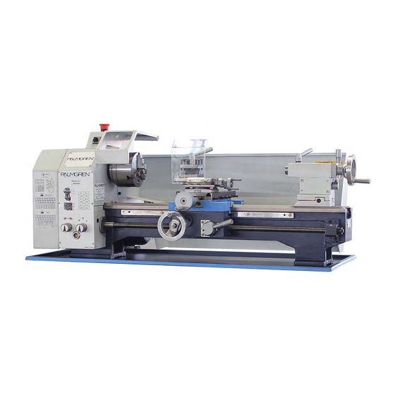
- Page 1 Operating manual Version 2.2.2 Lathe Item No. 9684509...
-
Page 2: Table Of Contents
Table of contents Safety Type plates ...............................6 Safety warnings (warning notes) ......................7 1.2.1 Classification of hazards...........................7 1.2.2 Other pictograms ............................8 Proper use ..............................8 Possible dangers caused by the machine ....................9 Qualification of personnel .........................9 1.5.1 Target group .............................9 1.5.2 Authorized personnel..........................10 1.5.3 Obligations of the operator ........................10 1.5.4 Obligations of the user..........................10 1.5.5 Additional qualification requirements ......................10... - Page 3 Optional machine accessories ....................... 27 Mounting instructions ..........................27 3.7.1 Mounting instruction chuck flange ......................27 3.7.2 Chuck flange TU2506 / TU2807V ......................28 3.7.3 Mounting instruction of collet chuck holder .................... 29 3.7.4 Mounting of movable rest - TU2506 ....................... 30 3.7.5 Mounting of movable rest - TU2807V.....................
- Page 4 Spare parts - TU2506 Top slide ..............................57 Cross slide ..............................58 Bed slide ..............................59 Tailstock..............................60 Machine bed ............................61 Feed gear 1 of 2 .............................62 Feed gear 2 of 2 .............................63 Headstock 1 of 2.............................64 Headstock 2 of 2.............................65 6.10 Change gear ............................66 6.11 Operating panel ............................67 6.12...
- Page 5 Preface Dear customer, Thank you very much for purchasing a product made by company. Company metal working machines offer a maximum of quality, technically company solutions and convince by an outstanding price performance ratio. Continuous enhancements and product innovations guarantee state-of-the-art products and safety at any time.
-
Page 6: Safety
Safety Glossary of symbols gives additional indications calls on you to act Enumerations This part of the operating manual explains the meaning and use of the warning references contained in the operating manual, explains how to use the lathe properly, ... -
Page 7: Safety Warnings (Warning Notes)
Safety warnings (warning notes) 1.2.1 Classification of hazards We classify the safety warnings into various levels. The table below gives an overview of the classification of symbols (pictograms) and warnings for the specific danger and its possible con- sequences. Alarm Pictogram Definition/Consequences expression... -
Page 8: Other Pictograms
1.2.2 Other pictograms Be aware of Activation forbidden! Pull the mains plug! Use protective gog- Use ear protection! slipping! gles! Use protective Use protective boots! Wear a safety suit! Protect the environ- Contact address gloves! ment! Proper use WARNING! Improper use of the lathe ... -
Page 9: Possible Dangers Caused By The Machine
Possible dangers caused by the machine The lathe has undergone a safety inspection (analysis of danger with assessment of risks). It has been designed and built on the basis of this analysis using the latest technological advances. Nonetheless, there remains a residual risk, since the machine operates with ... -
Page 10: Authorized Personnel
1.5.2 Authorized personnel WARNING! Incorrect use and maintenance of the machine constitutes a danger for personnel, objects and the environment. Only authorized personnel may operate the machine! The only personnel authorized to use this machine and perform maintenance on it are trained and instructed technical staff working for the operator and manufacturer. -
Page 11: Safety Devices
CAUTION! Risk of fire and explosion by using flammable materials or cooling lubricants. Take additional preventive measures in order to safely avoid health hazards before processing flammable materials (e.g. aluminum, magnesium) or before using flammable additives (e.g. alcohol). CAUTION! Risk of winding-up or cutting damages when using hand tools. The machine is not designed for the use of hand tools (e.g. -
Page 12: Lockable Main Switch
1.9.1 Lockable main switch It is possible to secure the lockable main switch with a padlock at the position "0" against switching on by mistake or unau- lockable thorized switching on. main switch When the main switch is switched off, the power supply to the machine is com- pletely interrupted. -
Page 13: Lathe Chuck Key
1.9.4 Lathe chuck key The lathe is equipped with self-ejecting key for chucks. Once the chuck key has been released, it will be ejected from the Lathe chuck key lathe chuck by its spring. CAUTION! Exclusively use the supplied chuck key to adjust the lathe chuck. -
Page 14: Individual Protection Gear
1.11 Individual protection gear For certain work individual protection gear is required. Protect your face and eyes: During all work, and specifically work during which your face and eyes are exposed to hazards, a safety helmet with a face guard should be worn. Use protective gloves when lifting or handling pieces with sharp edges. -
Page 15: Disconnecting The Lathe And Making It Safe
1.13 Disconnecting the lathe and making it safe Disconnect the lathe from power before beginning any maintenance or repair work. All machine components and hazardous voltages and movements must have been discon- nected. Secure the machine using a padlock on the lockable main switch. ... -
Page 16: Technical Data
Technical data The following information gives the dimensions and weight and is the manufacturer's authorized machine data. Power connection connection TU2506 TU2807V 115V,~ 60Hz, 1Ph, 0.75 kW 230V,~ 60Hz, 1Ph, 1.5 kW Motor (1Hp) (2Hp) Machine specifications TU2506 TU2807V Diameter three-jaw chuck 125mm (4.92") Distance between centers 550mm (21.63") -
Page 17: Emissions
Machine specifications TU2506 TU2807V Tailstock - sleeve diameter 30mm (1.181") Tailstock sleeve travel 65mm (2.56") 85mm (3.35") Tailstock cross adjustment + - 10 mm (0.39") Tailstock feed Lead Screw size 9/16" Dia - 10 TPI Tailstock feed Dial graduation 0.001" (1rev = 0.1") Work area TU2506 TU2807V... - Page 18 The following factors influence the actual degree of the noise disturbance of the operator: Characteristics of the working chamber, e.g. size or damping behavior, Other noise sources, e.g. the number of machines, Other processes proceeding nearby and the period during which the operator is exposed to the noise.
-
Page 19: Dimensions, Installation Plan Tu2506
Dimensions, installation plan TU2506 100 ( 4" ) 300 ( 11.8" ) 520 ( 20.5" ) 585 ( 23" ) 15 ( 0.6" ) 350 ( 13.8" ) 1115 ( 43.9" ) 1250 ( 49.2" ) 764 ( 30" ) 117 ( 4.6"... -
Page 20: Dimensions, Installation Plan Tu2807V
Dimensions, installation plan TU2807V 120 ( 4.7" ) 320 ( 12.6" ) 540 ( 21.5" ) 660 ( 26" ) 15 ( 0.6" ) 430 ( 17" ) 1290 ( 50.8" ) 1370 ( 54" ) 210 ( 8.3" ) 838 ( 33"... -
Page 21: Distance Between Centres, Height Of Centres Tu2506
Distance between centres, height of centres TU2506 Fig.2-3: Distance between centres, height of centres TU2506 ǀ TU2807V Page 21... -
Page 22: Distance Between Centres, Height Of Centres Tu2807V
2.10 Distance between centres, height of centres TU2807V Fig.2-4: Distance between centres, height of centres TU2506 ǀ TU2807V Page 22... -
Page 23: Assembly 3.1 Extent Of Supply
Assembly INFORMATION The lathe comes pre-assembled. Extent of supply When the machine is delivered, check immediately that the lathe has not been damaged dur- ing shipping and that all components are included. Also check that no fastening screws have come loose. Compare the parts supplied with the information on the packaging list. -
Page 24: Storage
Storage ATTENTION! Improper storage may cause important parts to be damaged or destroyed. Store packed or unpacked parts only under the following ambient conditions. Please follow the instructions and indications on the transportation box: Fragile goods (goods require careful handling) ... -
Page 25: Load Suspension Point
Provide sufficient space for assembly and operating staff as well as for material transport. Also allow for accessibility for setting and maintenance works. Make sure that the main power supply for the machine is freely accessible. Provide for sufficient illumination (minimum value: 300 lux, measured at the turning tool tip). -
Page 26: Cleaning And Greasing
3.5.1 Cleaning and greasing Remove the anticorrosive agent applied to the machine for transport and storage pur- poses. We recommend the use of WD-40 oil. Do not use any solvents, thinners or other cleaning agents which could corrode the varnish on the machine. -
Page 27: Optional Machine Accessories
Optional machine accessories WARNING! Risk by using improper workpiece clamping fixtures or by operating the machine with inadmissible speed. Only use the clamping fixtures (e.g. lathe chuck) which had been delivered together with the machine or as optional equipment offered by company. Use the working clamping fixtures only in the provided admissible speed range. -
Page 28: Chuck Flange Tu2506 / Tu2807V
3.7.2 Chuck flange TU2506 / TU2807V Unit [mm] Fig.3-1: Chuck flange TU2506 / TU2807V TU2506 ǀ TU2807V Page 28... -
Page 29: Mounting Instruction Of Collet Chuck Holder
3.7.3 Mounting instruction of collet chuck holder Mounting of collet chuck holder 344 1305 on your lathe TU2506 and TU2807V. Proceed as follows. Mark out the position of the lathe chuck at the spindle flange before dis- mantling with an e.g. felt-tipped pen. Spindle flange (short-taper seat) ... -
Page 30: Mounting Of Movable Rest - Tu2506
3.7.4 Mounting of movable rest - TU2506 Fig.3-3: Movable rest - TU2506 3.7.5 Mounting of movable rest - TU2807V Fig.3-4: Movable rest - TU2807V TU2506 ǀ TU2807V Page 30... -
Page 31: Mounting Of Steady Rest - Tu2506
3.7.6 Mounting of steady rest - TU2506 Fig.3-5: Steady rest - TU2506 3.7.7 Mounting of steady rest - TU2807V Fig.3-6: Steady rest - TU2807V TU2506 ǀ TU2807V Page 31... -
Page 32: Operation
Operation Safety Use the lathe only under the following conditions: The lathe is in proper working order. The lathe is used as prescribed. The operating manual is followed. All safety devices are installed and activated. All Troubleshooting should be eliminated immediately. Stop the machine immediately in the event of any abnormality in operation and make sure it cannot be started up accidentally or without authorisation. -
Page 33: Operation Tu2506
Operation TU2506 4.3.1 Control and indicating elements Description Description Protective cover of headstock Change-over switch with OFF position Emergency stop button Switch ON/ OFF Lathe chuck guard Jaw chuck Change gears and pitch/ feed table Selector switch for feed direction Selector switch for speed of feed of lathe saddle Handwheel lathe saddle Handwheel cross slide... -
Page 34: Switching Elements
4.3.2 Switching elements Fig.4-1: panel Hand actuated auxiliary switch ON The “hand actuated auxiliary switch ON” switches the rotation of the lathe on. Hand actuated auxiliary switch OFF The “hand actuated auxiliary switch OFF” switches the rotation of the lathe off. Main switch Disconnects or connects the power supply. -
Page 35: Operation Tu2807V
Operation TU2807V 4.4.1 Control and indicating elements Description Description Protective cover of headstock Change-over switch with OFF position Emergency stop button Push button ON Lathe chuck guard Jaw chuck Change gears and pitch/ feed table Selector switch for feed direction Selector switch for speed of feed of lathe saddle Handwheel lathe saddle Handwheel cross slide... -
Page 36: Switching Elements
4.4.2 Switching elements Hand actuated auxiliary switch ON The “hand actuated auxiliary switch ON” switches the rotation of the lathe on. Hand actuated auxiliary switch OFF The “hand actuated auxiliary switch OFF” switches the rotation of the lathe off. Speed adjustment It is possible to set the required speed using the speed adjustment. -
Page 37: Operating Elements For Infeed
Operating elements for infeed Feed speed Thread - Metric Threads Per Inch T.P.I. Leadscrew nut disengaged (Feed deactivated) Leadscrew nut engaged (Feed activated) Feed direction Toolholder Clamp the turning tool into the toolholder. The tool must be clamped firmly and with the least possible overhang in order to absorb well and reliably the cutting force generated during the chip formation. -
Page 38: Adjusting The Speed
If necessary, loosen the chuck by hitting it gently with a plastic-tipped hammer or a rubber mallet. Adjusting the speed WARNING! Disconnect the lathe from electrical power before opening the protective cover. Adjust the speed by changing the position of the V-belt on the pulleys. With the "Vario"... -
Page 39: Changing The Speed Range
4.8.1 Changing the speed range Loosen the nut on the tension pulley holder and Tension pulley holder release the tension of the V- belt. V-belt Install the V-belt into the Tension pulley corresponding position. Pulleys of primary transmission Motor pulley Fig.4-5: Tension pulley TU2506V... -
Page 40: Adjusting The Feed
Adjusting the feed 4.9.1 Selector switches Use the selector switches to select the feed direction and feed speed. ATTENTION! Selector switch for feed Wait until the machine has direction come complete halt before making any change to the selector switches. Selector switch for feed speed and thread pitch Fig.4-6:... -
Page 41: Assembly Of The Change Gears
Loosen the clamping nuts on the change gears. Clamping nuts Fig.4-9: Attachment of change gears Remove the slotted Slotted washer washers. Remove the screw from the shaft of the feed gear. Screw Fig.4-10: Attachment of change gears ... - Page 42 INFORMATION The assembly of the change wheels may be performed in the sequence that the standard gear (1st drive unit) first cams into gear B, then gear B to gear D and gear C to gear E. General According to DIN 868, the gear transmission ratio is the ratio of the driving gears to the driven gears.
-
Page 43: Gear Threading Tables
4.10.1 Gear threading tables INFORMATION The leads of thread, and/or longitudinal feeds represented in the following tables are possible with the gear wheels in the scope of supply. The tables are built up in a way that you may assemble the required combination of the gears to cut a thread without having to look up the details. -
Page 44: Example - Assembly Of Gear Wheels For Thread 14 Tpi, 28 Tpi And 56 Tpi On Tu2506
4.10.2 Example - assembly of gear wheels for thread 14 TPI, 28 TPI and 56 TPI on TU2506 Ligatures from one figure to the following one represent the cam- ing of one gear to the following one. The identifier "H" stands for bushing or a small gear as an auxiliary distance, see position 523 of spare parts drawing. -
Page 45: Immobilising The Lathe Saddle
4.12 Immobilising the lathe saddle The cutting force produced dur- ing facing, recessing or slicing process may displace the lathe saddle. Secure the lathe saddle using the tightening screw. tightening screw Fig.4-15: Lathe saddle TU2506 tightening screw Fig.4-16: Lathe saddle TU2807V 4.12.1 Turning tapers with the top slide ... -
Page 46: Tailstock Sleeve
4.13 Tailstock sleeve The tailstock quill is used to hold the tools (bits, lathe centres, etc.) Install the required tool in the tailstock quill. Use the scale on the quill to re-adjust and / or adjust the tool. ... -
Page 47: Replacing The Clamping Jaws On The Lathe Chuck
4.15 Replacing the clamping jaws on the lathe chuck The clamping jaws and the three-jaw chuck are provided with numbers. Check before the change, if the numbers are readable and, if necessary, mark the jaws and their primary position. Insert the clamping jaws at the correct position and in the right order into the three-jaw chuck. -
Page 48: Turning Speeds & Feeds
4.16 Turning Speeds & Feeds There are rules and principles of cutting speeds and RPM (revolutions per minute) calculations that apply to all metal cutting operations. The operating speed for all metal cutting operations is based on the cutting tool material and the hardness of the material to be cut. The hardness of the work material has a great deal to do with the recommended cutting speed. - Page 49 Cutting Speed, fpm Hardness Material Condition High-Speed Carbide Steel HR, N, A, CD 125 to 175 HR, N, A, CD 175 to 225 AISI 1027, 1029, 1030, 1032, N, CD, Q & T, 225 to 275 1035, 1037, 1040, 1043, 1045, 1047, N, Q &...
-
Page 50: Calculating Rpm
4.18 Calculating RPM The RPM setting depends on the cutting speed and the diameter of the part. The RPM setting will change with the diameter of the part. As the diameter of the part gets smaller, the RPM must increase to maintain the recommended surface feed. Conversely, as the diameter of the part gets larger, the RPM must decrease. -
Page 51: Selecting Feed Per Revolution
Note that the diameter of the drill and not the workpiece was used for RPM calculation. This was done because the cutting takes place at the diameter of the drill, not on the outside diame- ter of the workpiece. A turning operation is to be done on a 3.00-inch piece of 4140-alloy steel with a hardness of 200 HB. -
Page 52: Recommended Feed Rate Selection In Inches Per Revolution For Turning
4.18.2 Recommended Feed Rate Selection in Inches Per Revolution for Turning High-Speed Steel Carbide Material Roughing Finishing Roughing Finishing Low Carbon Steel 0.010 to 0.020 0.002 to 0.008 0.008 to 0.035 0.006 to 0.010 Med. Carbon Steel 0.008 to 0.018 0.002 to 0.008 0.008 to 0.030 0.006 to 0.010... -
Page 53: Maintenance
Maintenance In this chapter you will find important information about Inspection Maintenance Repair of the lathe. The diagram below shows which of these headings each task falls under. MAINTENANCE Inspection Maintenance Repairs Measuring Rough cleaning Mending Testing Fine cleaning Replacing Conserving... -
Page 54: Safety
Safety WARNING! The consequences of incorrect maintenance and repair work may include: Very serious injury to personnel working on the lathe Damage to the lathe Only qualified personnel should carry out maintenance and repair work on the lathe. 5.1.1 Preparation WARNING! Only carry out work on the lathe if it has been unplugged from the main power supply. - Page 55 Interval Where? What? How? Check the oil level in the gear's inspection glass. It must reach at least the centre of the inspection glass. If necessary, fill up to the reference mark with Mobilgear 627 or equivalent oil. Start of work after every Visual inspection...
-
Page 56: Repair
Interval Where? What? How? Lubricate all oilers with machine oil , do not use a grease gun or similar greasing equipment. Use the oil bottle in the delivery volume. "Operating material“ on page 17 every month Lubricate Oiler Illustr.5-4: Example, oiler on TU2807V Approximately every 100 operation hours a cleaning of the jaw guidance is to be performed, depending on the operating... -
Page 57: Top Slide
Spare parts - TU2506 Top slide Fig.6-1: Top slide TU2506 TU2506 Page 57... -
Page 58: Cross Slide
Cross slide Fig.6-2: Cross slide TU2506... -
Page 59: Bed Slide
Bed slide 75-2 75-1 Fig.6-3: Bed slide TU2506... -
Page 60: Tailstock
Tailstock Fig.6-4: Tailstock TU2506 TU2506 Page 60... -
Page 61: Machine Bed
Machine bed 441-1 441-2 441-3 Fig.6-5: Machine bed TU2506 TU2506 Page 61... -
Page 62: Feed Gear 1 Of 2
Feed gear 1 of 2 Fig.6-6: Feed gear TU2506 1 of 2... - Page 63 Feed gear 2 of 2 Fig.6-7: Feed gear TU2506 2 of 2...
-
Page 64: Headstock 1 Of 2
Headstock 1 of 2 424-1 424-2 436 434 430-1 430-2 Fig.6-8: Headstock TU2506 1 of 2... - Page 65 Headstock 2 of 2 236-2 236-1 Fig.6-9: Headstock TU2506 2 of 2...
-
Page 66: Change Gear
6.10 Change gear 505 - 516 505 - 516 505 - 516 Fig.6-10: Change gear... -
Page 67: Operating Panel
6.11 Operating panel Fig.6-11: switching elements USA TU2506 Page 67... -
Page 68: Spare Parts List Tu2506
6.12 Spare parts list TU2506 TU2506 Description Qty. Size Item no. Handle locking lever 034250011 Clamping nut tool holder 034250013 Washer clamping nut 034250014 Clamping screw 034250015 Quadruple tool holder 034250016 Pressure border top slide 034250017 Top slide with included inch thread 034250018-inch Threaded rod quadruple tool holder 034250019... - Page 69 TU2506 Description Qty. Size Item no. 75-2 Toothed shaft 03425001752 Threaded pin with tap ISO 7435 - M4 x 12 Toothed shaft 0342500180 DIN 6885 - A 4 x 4 x 12 Socket head screw GB 70-85 - M4 x 8 Washer ISO 7090 - 8 - 140 HV Hexagon nut...
- Page 70 TU2506 Description Qty. Size Item no. 236-2 Rack right section 034250012362 Countersunk screw ISO 7046-1 - M5 x 12 - 4.8 Lead screw inch 03425001238-inch Connecting piece 03425001239 Socket head screw GB 70-85 - M6 x 14 Saddle 03425001242 Cylindrical pin GB 120-86 - 6 x 16 Washer DIN 125 - A 10.5...
- Page 71 TU2506 Description Qty. Size Item no. O-ring DIN 3771 - 7.1 x 1.8 - N - NBR 70 Shaft rotary switch 03425001339 Adjusting lever 03425001340 Transmission fork 03425001341 Marking rotary switch 03425001342 Cylindrical pin ISO 2338 - 3 h8 x 14 Case 03425001344 Washer...
- Page 72 TU2506 Description Qty. Size Item no. Change gear 80 T Module 1.5 03425001-80 T Module 1.5 Change gear 72 T Module 1.5 03425001-72 T Module 1.5 Change gear 71 T Module 1.5 03425001-71 T Module 1.5 Change gear 70 T Module 1.5 03425001-70 T Module 1.5 Change gear 60 T Module 1.5...
- Page 73 TU2506 Description Qty. Size Item no. Washer 03425001938 Rivet 03425001939 Scale 03425001940 Eccentric cam 03425001941 Threaded pin ISO 4028 - M6 x 12 Washer 03425001944 Clamping lever 03425001945 Scale 03425001946 Saddle 03425001947 Base plate tailstock 03425001948 Tailstock upper section 03425001949 Clamping part collar 03425001950 Socket head screw...
- Page 74 TU2506 Page 74...
-
Page 75: Top Slide
Spare parts - TU2807V Top slide 38-2 38-1 Fig.7-1: Top slide TU2807V TU2807V Page 75... -
Page 76: Cross Slide
Cross slide Fig.7-2: Cross slide TU2807V Page 76... -
Page 77: Bed Slide
Bed slide Fig.7-3: lathe saddle TU2807V TU2807V Page 77... -
Page 78: Tailstock
Tailstock Fig.7-4: Tailstock TU2807V Page 78... -
Page 79: Machine Bed
Machine bed 441-1 441-2 404 402 441-3 Fig.7-5: Machine bed TU2807V Page 79... -
Page 80: Feed Gear 1 Of 2
Feed gear 1 of 2 Fig.7-6: Feed gear TU2807V 1 of 2... - Page 81 Feed gear 2 of 2 Fig.7-7: Feed gear TU2807V 2 of 2...
-
Page 82: Headstock 1 Of 2
Headstock 1 of 2 Fig.7-8: Headstock 1-2... - Page 83 Headstock 2 of 2 710A Fig.7-9: Headstock 2-2...
-
Page 84: Change Gear
7.10 Change gear 505 - 516 505 - 516 505 - 516 Fig.7-10: Change gear... -
Page 85: Spare Parts List Tu2807V
7.11 Spare parts list TU2807V TU2807V Description Qty. Size Item no. Clamping lever tool holder 034270011 Handle locking lever 034270012 Clamping nut tool holder 034270013 Washer clamping nut 034270014 Quadruple tool holder 034270015 Pressure border top slide 034270017 Top slide 034270018 Threaded rod quadruple tool holder 034270019... - Page 86 TU2807V Description Qty. Size Item no. Axially grooved ball bearing 51101 0342700169 Appron 0342700171 Handwheel bed slide 0342700172 Handle handwheel bed slide 0342700173 Fixing bolt handle handwheel 0342700174 Circlip DIN 471 - 15 x 1 Saddle 0342700177 Socket head screw GB 70-85 - M5 x 25 Back support 0342700179...
- Page 87 TU2807V Description Qty. Size Item no. Lathe bed 03427001235 Rack 03427001236 Socket head screw GB 70-85 - M6 x 16 Lead screw inch 03427001238-inch Connecting piece 03427001239 Socket head screw GB 70-85 - M8 x 25 Saddle 03427001242 Groove nut DIN 1804 - M12 Washer DIN 125 - A 13...
- Page 88 TU2807V Description Qty. Size Item no. DIN 3771 - 15 x 1.8 - N - NBR O-ring Socket right 03427001349 Sliding bearing intermediate shaft 03427001350 Socket head screw GB 70-85 - M6 x 50 Oil sight glass 25 mm 03427001360 O-ring DIN 3771 20x2,65 Washer...
- Page 89 TU2807V Description Qty. Size Item no. Shim 3 mm 03425001519 Connecting case of change gears 03425001520 Clamping screw change gear 03425001521 Attachment ring 03425001522 Case change gear 03425001523 Washer 03425001524 Socket head screw DIN 912 M6 x 10 Splash wall 03427001601 Splash wall TU2807V 03427006601...
- Page 90 TU2807V Description Qty. Size Item no. Innensechskantschraube 03427001929 Spring pin ISO 8752 - 4 x 28 A Guide bush 03427001931 Spring pin ISO 8752 - 4 x 24 A Threaded rod 03427001933 Tightening screw 03427001934 Spring 03427001935 Clamping plate 03427001936 Hexagon nut ISO 4035 - M12 Washer...
- Page 91 Viskosity Designation ISO VG Lubricant according DIN 51519 DIN 51502 mm²/s (cSt) Aral Degol BP Energol SPARTAN Klüberoil Mobilgear Shell Omala VG 680 CLP 680 Meropa 680 BG 680 GR-XP 680 EP 680 GEM 1-680 Aral Degol BP Energol SPARTAN Klüberoil Mobilgear Shell Omala...
-
Page 92: Wiring Diagrams
Wiring diagrams TU2506 Fig.8-1: Wiring diagram-TU2506 TU2506 ǀ TU2807V Page 92... -
Page 93: Tu2807V (230V)
TU2807V (230V) Fig.8-2: Wiring diagram-TU2807V TU2506 ǀ TU2807V Page 93... -
Page 94: Troubleshooting
Troubleshooting Troubleshooting in the lathe Problem Cause / possible effects Solution Machine does not switch-on • Precedence of switch-on not con- • "Power supply“ on page 26 sidered. • The position switch of the lathe- • Check and adjust the position chuck guard switches the lathe off. -
Page 95: Appendix 10.1 Copyright
Appendix 10.1 Copyright This documentation is copyright. All derived rights are also reserved, especially those of transi- tion, re-printing, use of figures, broadcast, reproduction by photo-mechanical or similar means and recording in data processing systems, neither partial nor total. The company reserves the right to make technical alternations without prior notice. 10.2 Terminology/glossary Term... -
Page 96: Limited Warranty
10.3 LIMITED WARRANTY COMPANY ONE-YEAR LIMITED WARRANTY. COMPANY, MODELS COVERED IN THIS MANUAL, ARE WARRANTED BY COMPANY TO THE ORIGINAL USER AGAINST DEFECTS IN WORKMANSHIP OR MATERIALS UNDER NORMAL USE FOR ONE YEAR AFTER DATE OF PURCHASE. ANY PART WHICH IS DETERMINED TO BE DEFECTIVE IN MATERIAL OR WORKMANSHIP AND RETURNED TO AN AUTHORIZED SERVICE COMPANY DESIGNATES, SHIPPING COSTS PREPAID, WILL BE, LOCATION,... -
Page 97: Ec - Declaration Of Conformity
Index Adjusting the feed ..........40 Change gears ............40 Changing the change gears ........40 Cleaning and greasing ..........26 Cross-adjustment of the tailstock ......45 First use ..............25 Functional test ............26 Installation .............25 LIMITED WARRANTY ..........96 Maintenance ............53 Mechanical maintenance work ......15 Mounting instruction chuck flange .............27 collet chuck holder ...........29 Operation... -
Page 98: Ec - Declaration Of Conformity
TU2506 ǀ TU2807V Page 98...
Need help?
Do you have a question about the TU 2506 and is the answer not in the manual?
Questions and answers