Table of Contents
Advertisement
Quick Links
Advertisement
Table of Contents

Related Manuals for Palmgren TU 1503V


Summary of Contents for Palmgren TU 1503V
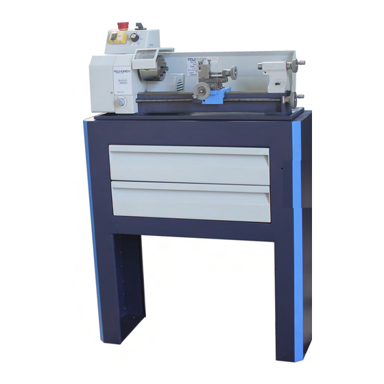
- Page 1 Operating manual Version 1.0.3 Lathe Item no:9684495 Shown with Optional Stand...
-
Page 2: Table Of Contents
Table of contents Safety Safety instructions (warning notes)......................7 1.1.1 Classification of hazards...........................7 1.1.2 Other pictograms ............................8 Intended use .............................8 Reasonably foreseeable misuses......................9 1.3.1 Avoiding misuses............................9 Possible dangers caused by the machine ....................9 Qualification of personnel ........................10 1.5.1 Target group ............................10 1.5.2 Authorized personnel..........................11 1.5.3 Obligations of the operating company ....................11 1.5.4 Obligations of the operator ........................11... - Page 3 5.2.1 Switching elements ..........................26 5.2.2 Switching on the machine ........................26 5.2.3 Switching off the machine ........................27 Clamping a tool ............................27 5.3.1 Tool height.............................. 27 Speed adjustment ..........................28 5.4.1 Changing the speed range ........................28 Straight turning ............................29 5.5.1 Manually ..............................
- Page 4 Ersatzteilzeichnung Reitstock - Drawing spare parts tailstock ..............69 8.6.1 Ersatzteile Reitstock - Spare parts tailstock ..................70 Ersatzteilzeichnung Wechselradgetriebe - Drawing spare parts change gear ........71 8.7.1 Ersatzteile Wechselradgetriebe - Spare parts change gear ..............72 Maschinenschilder - Machine labels.......................73 8.8.1 Maschinenschilder - Machine labels.......................73 Schaltplan - Wiring diagram........................74 8.9.1 Ersatzteile elektrische Bauteile - Spare parts electrical components ............75 Malfunctions...
- Page 5 Preface Dear customer, Thank you very much for purchasing a product made by company. Company metal working machines offer a maximum of quality, technically company solutions and convince by an outstanding price performance ratio. Continuous enhancements and product innovations guarantee state-of-the-art products and safety at any time.
-
Page 6: Safety
Safety Glossary of symbols gives further advice calls on you to act enumerations This part of the operating instructions explains the meaning and use of the warning notices included in these operating instruc- tions, defines the intended use of the lathe, ... -
Page 7: Safety Instructions (Warning Notes)
Safety instructions (warning notes) 1.1.1 Classification of hazards We classify the safety warnings into various levels. The table below gives an overview of the classification of symbols (ideogram) and the warning signs for each specific danger and its (possible) consequences. Ideogram Warning alert Definition / consequence... -
Page 8: Other Pictograms
1.1.2 Other pictograms Warning danger of Caution, danger of Warning of automatic Warning hot surface! Warning biological slipping! explosive substances! start-up! hazard! Switching on Pull the main plug! Use safety glasses! Use ear protection! Use protective forbidden! protection gloves! Use protective boots! Use protective suit! Protect the Contact address... -
Page 9: Reasonably Foreseeable Misuses
In order to achieve company cutting performance, it is essential to choose the right turning tool, feed, tool pressure, cutting speed and coolant. "Appendix turning“ on page 33 WARNING! Heaviest injuries through improper use. It is forbidden to make any modifications or alternations to the operation values of the lathe. -
Page 10: Qualification Of Personnel
INFORMATION Everyone involved in the assembly, commissioning, operation and maintenance must be duly qualified, strictly follow these operating instructions. In the event of improper use there may be a risk to the personnel, there may be a risk to the machine and other material values, ... -
Page 11: Authorized Personnel
Instructed person Instructed personnel were instructed by the operating company about the assigned tasks and any possible risks in case of improper behaviour. INFORMATION Everyone involved in the assembly, commissioning, operation and maintenance must be duly qualified, strictly follow these operating instructions. In the event of improper use ... -
Page 12: Operators Positions
Operators positions The operator’s position is in front of the machine. Safety measures during operation CAUTION! Risk due to inhaling of health hazardous dusts and mist. Dependent on the material which need to be processed and the used auxiliaries dusts and mist may be caused which might impair you health. -
Page 13: Emergency-Stop Button
EMERGENCY-STOP button EMERGENCY-STOP button switches the lathe off. Knocking on the emergency stop device EMERGENCY- triggers an emergency stop. STOP button After actuating the switch, turn it to the right, in order to restart the lathe. Img.1-1: EMERGENCY-STOP button 1.9.1 Protective cover with safety switch The spindle head of the lathe is equipped with a fixed, separating protective cover. -
Page 14: Safety Check
1.10 Safety check Check the lathe regularly. Check all safety devices before starting work, once a week, after every maintenance and repair work. General check Equipment Check Protective covers, Mounted, firmly bolted and not damaged lathe chuck protection Signs, Installed and legible Markings... -
Page 15: Disconnecting And Securing The Lathe
WARNING! Before switching on the lathe make sure that there are no no dangers generated for persons, not cause damage to equipment. Avoid any risky working practices: Make sure that nobody is endangered by your work. Clamp the workpiece tightly before activating the lathe. -
Page 16: Technical Data
Technical data The following information are the dimensions and indications of weight and the manufacturer‘s approved machine data.. Electrical connection 110V ; 5/8HP ; 60Hz Total connection rate Degree of protection IP 54 Machine data Height of centres [mm] Max. swing [mm] Max. -
Page 17: Emissions
Environmental conditions Humidity 25 - 80 % Emissions The generation of noise emitted by the lathe is less than 70 dB(A). If the lathe is installed in an area where various machines are in operation, the noise exposure (immission) on the operator of the at the working place may exceed 80dB(A). INFORMATION This numerical value was measured on a new machine under proper operating conditions. -
Page 18: Dimensions, Installation Plan
Dimensions, installation plan Img.2-1: Dimensions, installation plan TU1503V Page 18 Original operating instructions Version 1.0.3 dated 2014-05-14... -
Page 19: Unpacking And Connecting
Unpacking and connecting INFORMATION The lathe is delivered pre-assembled. When the lathe is delivered, check immediately before and after unpacking hat the lathe has not been damaged during shipping and that all compo- nents are included. Also check that no fastening screws have come loose. Scope of delivery Compare the scope of delivery with the packing list. -
Page 20: Installation And Assembly
Installation and assembly 3.3.1 Requirements regarding the installation site INFORMATION In order to attain good functionality and a high processing accuracy as well as a long durability of the machine the installation site should fulfil certain criteria. Please observe the following points: ... -
Page 21: Warming Up The Machine
Only use the tool holders (e.g. drill chuck) which were delivered with the machine or which are offered as optional equipment by company. Only use tool holders in the intended admissible speed range. Tool holders may only be modified in compliance with the recommendation of company or of the manufacturer of the clamping devices. -
Page 22: Assembly And Function
Assembly and function The machine is a centre lathe. It has been designed and manufactured for straight turning and facing round or regularly-formed square workpieces in metal, plastics or similar materials for model making. The hollow work spindle enables you to clamp longer workpieces with a diameter of up to 10 The speed is changed progressively in the predefined speed range of the corresponding V-belt pulley. -
Page 23: Gear
4.2.1 Gear By changing the position of the V-belt on the pulleys you can select two speed ranges. The potentiometer is used to change the speed within the corresponding speed range. V-belt Img.4-2: V-belt 4.2.2 Feed gear The feed gear is used to obtain the feeds for straight turning and threading by changing the change gears. -
Page 24: Cross Slide
Cross slide The cross slide is connected to the lathe saddle (saddle slide) with the help of a dovetail slide- way. Movement is at right angles to the workpiece axis by means of the cross slide. Tailstock The tailstock consists of a guide plate with gripping yoke and upper part. It is readjusted manu- ally and clamped on the slideways of the lathe bed with the help of the clamping screw and the gripping yoke. -
Page 25: Handling
Handling Safety Use the lathe only under the following conditions: The lathe is in proper working order. The lathe is used as prescribed. The operating manual is followed. All safety devices are installed and activated. All failures should be eliminated immediately. Stop the immediately in the event of any abnor- mality in operation and make sure it cannot be started-up accidentally or without authorisation. -
Page 26: Gb Tu1503V
5.2.1 Switching elements Push button ON The “hand actuated auxiliary switch ON” switches the rotation of the lathe on. Hand actuated auxiliary switch OFF The “hand actuated auxiliary switch OFF” switches the rotation of the lathe off. Speed adjustment It is possible to set the required speed using the speed adjustment. Rotation direction switch The direction of rotation of the lathe can be switched by actuating the change-over switch. -
Page 27: Switching Off The Machine
5.2.3 Switching off the machine Actuate the push button "OFF". If the machine stands still for a longer period of time, disconnect the machine from the electri- cal power supply. WARNING! Risk by using improper workpiece clamping materials or by operating the machine with inadmissible speed. -
Page 28: Speed Adjustment
Speed adjustment Adjust the speed with the potentiometer. In order to use another speed range, you must change the position of the V-belt on the pulleys. WARNING! Unplug the shockproof plug of the lathe before opening the protective cover of the spindle stock. -
Page 29: Straight Turning
Straight turning See also "Anhang Drehen“ on page 34 5.5.1 Manually In the straight turning operation, the tool feeds parallel to the axis of rotation of the workpiece. The feed can be either manual - by turning the handwheel on the lathe saddle or the top slide - or by activating the automatic feed. -
Page 30: Clamping A Workpiece Into The Three Jaw Chuck
Clamping a workpiece into the three jaw chuck When the workpiece is being clamped unprofessionally, there is a risk of injury as the work- piece may fly off or the jaws may break. The following examples do not show all possible situa- tions of danger. -
Page 31: Adjusting Feeds And Thread Pitches
Adjusting feeds and thread pitches To change the feed or obtain a certain metric thread pitch, change the change gears according to the table. Gear belt The table may also be found in the inner part of the protective cover of the Change gear "Z1"... -
Page 32: Changing The Change Gears
5.10 Changing the change gears Example: To obtain a thread pitch of 1 mm, you have to perform the following tasks. Unplug the shockproof plug from the mains. Open the protective cover of the spindle stock. Clamping screw ... -
Page 33: Appendix Turning
Appendix turning Turning is a cutting manufacturing process with certain geometrically positive or negative cut- ting edge geometries. For the machining on the outside tool holder with quadrate shaft and for the machining on the inside boring bars with rounded or oblated shafts are used (refer to ISO-code for tool holders and boring bars). -
Page 34: Iso-Designation System For Tool Holder, Inside Machining
Img.6-9: boring bar for thread cutting Img.6-8: tool holder for thread cutting ISO-designation system for tool holder, inside machining Material of the body Shank diameter Tool length Type of fixture Identification of letter Material of the body Construction features Steel cutter none with inner coolant feeding... -
Page 35: Iso-Designation System For Tool Holder, Outside Machining
ISO-designation system for tool holder, outside machining Type of fixture Form of the indexable inserts Form of the tool holder Free angle of the indexa clamped at the top clamped at the top above the hole clamped above the hole screwed through the hole free angles... -
Page 36: Cutter With Hard Metal Reversible Carbide Tip Soldered On
Cutter with hard metal reversible carbide tip soldered on Img.6-10: straight cutter DIN 4971 Img.6-11: bent cutter DIN 4972 ISO 1 ISO 2 Img.6-12: inside tool DIN 4973 Img.6-13: internal side turning tool for corner work ISO 8 DIN 4974 ISO 9 Img.6-14: tip of cutter DIN 4975 Img.6-15: cutter width DIN 4976... -
Page 37: Outside Machining, Longitudinal Turning And Facing
cording to ISO, the height of the cutting point is half the shank diameter and for flattened drill rods half the flattened height. For inside tools according to DIN the height of the cutting point corresponds to 0,8 x shank diameter respectively shank height. ATTENTION! If due to a variation in tolerance there is a slug or cone on the plane face, the exact height of centers is to be found by facing trials (put the tool holder higher for slugs and lower for cones). -
Page 38: Inside Machining, Drilling And Longitudinal Turning
For facing the bedslide is to be fixed with the clamping screw. The feed is performed by turning the handwheel of the cross slide. The infeed of the depth of cut is performed with the hand- wheel of the top slide. Advance of depth of cut Feed direction Img.6-21: Facing operation... -
Page 39: Thread Types
Img.6-22: die Img.6-23: screw tap Bolts and nuts with large thread diameters, deviating thread pitches or special types of thread,right-handed and left-handed threads may be produced by threading. For this manufac- turing there are as well tool holders and drill rods with exchangeable indexable inserts (one- edged or multiple-edged). - Page 40 Whitworth B.S.W. 1/4" in. -20 B.S.W. Bolt ISO-trapezoid Tr 40 x 7 thread Tr 40 x 14 P7 (one- and multi- ple- threaded) Bolt Round thread RD DIN 405 Bolt 1“ – 11 ½“ NPT Cone Bolt Page 40 Original operating instructions Version 1.0.3 dated 2014-5-14...
-
Page 41: Metric Threads (60° Flank Angle)
Metric threads (60° flank angle) pitch P depth of thread of the bolt h2=0,6134 x P depth of thread of the nut H1 = 0,5413 x P rounding r = 0,1443 x P flank diameter d2 = D2 =d - 0,6493 Bolt core removing hole drill = d - P flank angle = 60°... -
Page 42: British Thread (55° Flank Angle)
M 30 27.727 25.706 26.211 2.147 1.894 0.505 26.5 M 36 33.402 31.093 31.670 2.454 2.165 0.577 M 42 39.077 36.479 37.129 2.760 2.436 0.650 37.5 M 48 44.752 41.866 41.866 3.067 2.706 0.722 M 56 52.428 49.252 49.252 3.374 2.977 0.794 50.5... - Page 43 BSPT: BSPT: British Standard Pipe - Taper Thread. Conic tube thread, cone 1:16; designation: 1/4" - 19 BSPT BA: BA: British Association Standard Thread (47 1/2° flank angle). Common with instruments and watches, is being replaced by the metric ISO thread and by the ISO miniature thread. It consists of numeric designations from 25 to 0=6,0mm max diameter.
-
Page 44: Indexable Inserts
6.8.2 Indexable inserts For indexable inserts there are partial profile and full profile indexable inserts. The partial pro- file indexable inserts are designed for a certain pitch range (e.g. 0.5 - 3mm). The partial profile indexable insert is optimally appropriate for the single-piece production. ... -
Page 45: Examples For Thread Cutting
6.8.3 Examples for thread cutting As an example, a metric external thread M30 x 1,0 mm made of brass is being machined. Selecting the tool holder For lathe TU1503V and TU1804V , TU2004V, turning tool No.6 and for lathe TU2404 , TU2404V, TU2506 , TU2506V, TU2807 , TU2807V turning tool No.13. - Page 46 The depth of thread is manufactured in various passes. The infeed is to be reduced after each pass. The first pass takes place with an infeed of 0.1 - 0.15 mm For the last pass the infeed shall not be below 0,04mm.
-
Page 47: Recessing, Cutting Off And Turning Off
Starting the threading: Radial infeed over the handwheel of the cross slide. Turn the change-over, switch to the right Start the machine and have the first cutting process run. ATTENTION! Always have the thumb ready on the OFF-switch in order to prevent a collision with the workpiece or with the clamping chuck ! ... -
Page 48: Turning Of Cones With High Precision
Img.6-38: recessing 1 Img.6-39: recessing 2 On a shaft made of brass, an undercut for a thread M30 is to be machined. Groove with 5,0mm with a depth of 2,5mm. Selecting the tool holder For lathe TU1503V and TU1804V , TU2004V, turning tool No.7 and for lathe TU2404 , TU2404V, TU2506 , TU2506V, TU2807 , TU2807V turning tool No.14. - Page 49 Calculation of the offset of the top slide relating to the stop measure with a length of 100mm. Step by step 100mm ------------ - ------------------ - ------ - – by one calculation step (summary) 100mm – ------------------------------------------ - ...
- Page 50 By measuring an existing cone with gauge and stand. The stand is put on the top slide. The gauge is aligned horizontally and 90° to the top slide. The top slide is approximately adjusted to the cone angle and the test prodbrought in contact with the cone surface (fix the bedslide).
-
Page 51: Cutting Materials
Example: Kv = 1 : 40 ; Lw = 150 mm ; L = 100 mm -------------- - -------- - 1 875mm Vr max Img.6-43: Workpiece between points: Tailstock offset Vr 6.11 Cutting materials The basic requirement for a cutting material is that it is harder than the material which is to be worked. -
Page 52: Standard Values For Cutting Data When Turning
Cermet (uncoated and coated) Cermet (ceramic-metal) is a hard metal on the basis of titanium carbide. The cutting material has very good wear resistance and edge strength. Indexable inserts made of Cermet are used with high cutting speeds for planing. Cutting ceramics Cutting ceramics is composed of non-metalic anorganic material. -
Page 53: Cutting Speed Table
Infeed The infeed for roughing/turning is to be selected in a way that it does not exceed buff the value of the corner radius. Example: r = 0.4mm ; equals to fmax. = 0.2 mm/rev ! For planing/turning the infeed should be maximum 1/3 of the corner radius. Example: r = 0.4mm ;... -
Page 54: Terms For The Rotating Tool
6.14.1 Terms for the rotating tool Cutting direction Chip thickness Chip surface Tool Clearance surface Img.6-44: Geometrically Img.6-45: Cut and chip size determined cut- ter for the separa- tion process Chip surface Chip surface Chip angle negative Chip angle ... -
Page 55: Cutting Edge Geometry For Turning Tools
6.14.2 Cutting edge geometry for turning tools High-speed steel Hard metal Clearance Clearance Chip angle Chip angle angle angle Steel +5° to +7° +5° to +6° +5° to +11° +5° to +7° Cast non +5° to +7° +5° to +6° +5°... - Page 56 Img.6-52: Negative apex angle for roughing The ready-ground major cutting edge must be slightly ground with a grindstone for the plan- ing. For the roughing, a small chamfer must be produced with the grindstone in order to stabilize the cutting edge against striking chips (b = f x 0.8).
-
Page 57: Lifetime And Wear Characteristics
Img.6-55: Polished section for threading 6.15 Lifetime and wear characteristics In the chipping shaping by lifetime we understand the time which the cutting edge survives (pure contact time). The causes for the end of the lifetimes may be the following: ... -
Page 58: Maintenance
Maintenance In this chapter you will find important information about Inspection Maintenance Repair of the lathe. ATTENTION ! Properly performed regular maintenance is an essential prerequisite for operational safety, failure-free operation, long durability of the lathe and ... -
Page 59: Repair
Interval Where? What? How? Grease the leadscrew on the lubricating nipple. Lubricating nipple Every month Lubricating Img.7-1: Feed gear Control if the synchronous belts are porous or every six Visual inspection months worn. Readjust the slideway clearance of the cross and top slide. - Page 60 TU1503V Page 60 Original operating instructions Version 1.0.3 dated 2014-05-14...
-
Page 61: Ersatzteile - Spare Parts
Ersatzteile - Spare parts Ersatzteilzeichnung Antrieb - Drawing spare parts actuation Abb.8-1: Antrieb - Actuation... -
Page 62: Ersatzteilzeichnung Spindelstock - Drawing Spare Parts Headstock
Ersatzteilzeichnung Spindelstock - Drawing spare parts headstock Abb.8-2: Spindelstock - Headstock... -
Page 63: Ersatzteilzeichnung Abdeckungen - Drawing Spare Parts Covers
Ersatzteilzeichnung Abdeckungen - Drawing spare parts covers Abb.8-3: Abdeckungen - Covers... -
Page 64: Ersatzteilliste Antrieb, Spindestock - Spare Parts List Actuation, Headstock
8.3.1 Ersatzteilliste Antrieb, Spindestock - Spare parts list actuation, headstock Menge Grösse Artikelnummer Bezeichnung Designation Quan- Size Article no. tity Sicherungsring Retaining ring DIN 471 - 8x0,8 Kugellager Ball bearing 698-2Z 040698.Z Keilriemenscheibe V-belt pulley 0342025105 Feste Welle Fix shaft Gewindestift Grub screw GB 79-85 - M5 x 8... -
Page 65: Ersatzteilzeichnung Planschlitten, Oberschlitten- Drawing Spare Parts Cross Slide, Top Slide
Ersatzteilzeichnung Planschlitten, Oberschlitten- Drawing spare parts cross slide, top slide Abb.8-4: Planschlitten, Oberschlitten - Cross slide, top slide... -
Page 66: Ersatzteile Planschlitten, Oberschlitten - Spare Parts List Cross Slide, Top Slide
8.4.1 Ersatzteile Planschlitten, Oberschlitten - Spare parts list cross slide, top slide Menge Grösse Artikelnummer Bezeichnung Designation Quan- Size Article no. tity To be updated Werkzeughalter Tool rest(inch) Innensechskantschraube Socket head screw GB 70-85 - M6 x 20 Sechskantmutter Hexagon nut ISO 4032 - M3 Gewindestift Grub screw... -
Page 67: Ersatzteilzeichnung Maschinenbett - Drawing Spare Parts Machine Bed
Ersatzteilzeichnung Maschinenbett - Drawing spare parts machine bed Abb.8-5: Maschinenbett - Machine bed... -
Page 68: Ersatzteile Maschinenbett - Spare Parts List Machine Bed
8.5.1 Ersatzteile Maschinenbett - Spare parts list machine bed Menge Grösse Artikelnummer Bezeichnung Designation Quan- Size Article no. tity Maschinenbett Machine bed 03420251301 Gewindestift Grub screw GB 80-85 - M5 x 6 Buchse Bushing 03420251303 To be updated Skalenring Scale ring(inch) Handrad Handwheel 03420251305... -
Page 69: Ersatzteilzeichnung Reitstock - Drawing Spare Parts Tailstock
Ersatzteilzeichnung Reitstock - Drawing spare parts tailstock Abb.8-6: Reitstock - Tailstock... -
Page 70: Ersatzteile Reitstock - Spare Parts Tailstock
8.6.1 Ersatzteile Reitstock - Spare parts tailstock Menge Grösse Artikelnummer Bezeichnung Designation Quan- Size Article no. tity Zentrierspitze Dead center 03420251401 Pinole Pinole 03420251402 Innensechskantschraube Socket head screw GB 70-85 - M6 x 35 Gewindestift Grub screw GB 80-85 - M4 x 6 Innensechskantschraube Socket head screw GB 70-85 - M6 x 14... -
Page 71: Ersatzteilzeichnung Wechselradgetriebe - Drawing Spare Parts Change Gear
Ersatzteilzeichnung Wechselradgetriebe - Drawing spare parts change gear Abb.8-7: Wechselradgetriebe - Change gear... -
Page 72: Ersatzteile Wechselradgetriebe - Spare Parts Change Gear
8.7.1 Ersatzteile Wechselradgetriebe - Spare parts change gear Menge Grösse Artikelnummer Bezeichnung Designation Quan- Size Article no. tity Führungsplatte Support plate 03420251503 Sechskantschraube Socket head screw GB 6170-86 - M5 Zahnrad Gear Z=17 03420251508 Schraube Screw 03420251509 Scheibe Washer 03420251510 Innensechskantschraube Socket head screw GB 70-85 - M5 x 35... -
Page 73: Maschinenschilder - Machine Labels
Maschinenschilder - Machine labels Abb.8-8: Maschinenschilder - Machine labels 8.8.1 Maschinenschilder - Machine labels Menge Grösse Artikelnummer Bezeichnung Designation Quan- Size Article no. tity Sicherheitsschild Safety label 03420251L01 Frontschild Front label 03420251L02 Sicherheitsschild Safety label 03420251L04 Sicherheitsschild Safety label 03420251L05 Hinweisschild Instruction label 03420251L06... -
Page 74: Schaltplan - Wiring Diagram
Schaltplan - Wiring diagram Abb.8-9: Schaltplan - Wiring diagram... -
Page 75: Ersatzteile Elektrische Bauteile - Spare Parts Electrical Components
8.9.1 Ersatzteile elektrische Bauteile - Spare parts electrical components Menge Grösse Artikelnummer Bezeichnung Designation Quan- Size Article no. tity Sicherung Fuse 034202601F1 Ein-Aus-Schalter On-Off switch 034202601S1 Netzfilter Line filter 034202601Z1 Steuerplatine Control board 034202601A2 Potentiometer Potentiometer 034202601R4 Drehrichtungsschalter Change over switch 034202601S4 Motor Motor... -
Page 76: Malfunctions
Malfunctions Malfunctions on the lathe Cause/ Malfunction Solution possible effects Surface of workpiece too • Tool blunt • Resharpen tool rough • Tool springs • Clamp tool with less overhang • Feed too high • Reduce feed • Radius at the tool tip too small •... -
Page 77: Appendix 10.1 Copyright
Appendix 10.1 Copyright This document is copyright. All derived rights are also reserved, especially those of translation, re-printing, use of figures, broadcast, reproduction by photo-mechanical or similar means and recording in data processing systems, neither partial nor total. Subject to technical changes without notice. 10.2 Terminology/Glossary Term... -
Page 78: Liability Claims For Defects / Warranty
10.4 Liability claims for defects / warranty Beside the legal liability claims for defects of the customer towards the seller the manufacturer of the product, company does not grant any further warranties unless they are listed below or had been promised in the frame of a sin-gle contractual agreement. The processing of the liability claims or of the warranty is performed as chosen by company ... -
Page 79: Decommissioning
10.5.1 Decommissioning CAUTION! Used devices need to be decommissioned in a professional way in order to avoid later misuses and endangerment of the environment or persons. Pull off the mains plug. Cut the connection cable. Remove all environmentally hazardous operating fluids from the used device. ... -
Page 80: Disposal Via Municipal Collection
The disposal notes for the used lubricants are made available by the manufacturer of the lubri- cants. If necessary, request the product-specific data sheets. 10.6 Disposal via municipal collection Disposal of used electrical and electronic components (Applicable in the countries of the European Union and other European countries with a sepa- rate collecting system for those devices). - Page 81 Index Appendix turning ..........33 Safety instructions ............7 Scope of delivery ..........19 Cone ..............48 Control elements ..........26 Cutting materials ..........51 Technical data Cutting off ............. 47 dimensions ............16 Cutting speed Emissions ............17 ................ 52 Environmental conditions .........16 Cutting speed table ..........
Need help?
Do you have a question about the TU 1503V and is the answer not in the manual?
Questions and answers