Table of Contents

Related Manuals for KIPI ROT-POWER Series

Summary of Contents for KIPI ROT-POWER Series
- Page 1 Service Manual Unit: Pellet burner Type: ROT-POWER Models: 4-16 kW, 5-20 kW, 6-26 kW, 8-36 kW, 10-50 kW. BTI GUMKOWSKI Sp. z o.o. Sp.k. ul. Obornicka 71, 62-002Suchy Las Tel. +48 606-936-692, +48 61-811-70-37 biuro@kipi.pl update: 20-04-2016...
-
Page 2: Table Of Contents
Contents Unit Description ………………………………………………………….. Fuel Specification…………………………………………………………. Construction and Operation of the Burner………………………………... Components……………………………………………………………….. Assembling the Unit………………………………………………………. Starting up…………………………………………………………………. 16 Operation of the burner in the operational mode…………………………. List of common problems…………………………………………………. Maintenance, adjustment and servicing the burner………………………. Operational Safety………………………………………………………..Burner Liquidation after its Service Life is Over………………………… Electric diagram……………………………………………………………... -
Page 3: Unit Description
1. Unit Description. Burners ROT-POWER series are designed for solid fuels combustion in the form of pellets with different degrees of pollution and grain size (according to this specification, point 2). The burner operates automatically and does not require supervision. Rotation of a combus- tion chamber prevents adhesion of slag to the chamber formed during combustion. -
Page 4: Fuel Specification
2. Fuel Specification. The burner should only be supplied by fuel with the following properties: Fractions grain size 6±1mm, 8±1mm Diameter Length 3,15mm - 40 mm ≤ 1% Dust fraction ≥ 600 kg/m Density ≤ 10% Moistness 16,5÷19 MJ/kg Calorific value ≤... - Page 5 Fig. 1. Block diagram of the burner.
- Page 6 Construction and Operation of the Burner. ROT-POWER burner is built with connected modules and metal sheet components. Components exposed to high temperatures are made of stainless and heat resistant steel, other elements are protected against external factors by galvanic coating or painting. External fuel feeder (5) is made of stainless steel tube.
- Page 7 chamber; its triggering temperature is 90 C. It is a constant alarm, which may be removed only by the user. Another safety element is the structure of the fuel delivery system - the use of two augers (the first extracts fuel from the external tank and the second supplies the fuel into the combustion chamber inside the burner) connected by a flexible (meltable) plastic hose which divides the stream of the supplied fuel.
-
Page 8: Components
4. Components. The burner is supplied with the following components: Components Burner ROT-POWER Controller (driver) from Plum The auger feeder from the external tray to the burner (operational length: 1,85 m with an extension option), Flexible hose (meltable) - length: 0.75 m for connecting the burner with the auger feeder, Elbow connection Emergency mechanical sensor for boiler temperature with wiring... - Page 9 Fig. 2. Components of the set...
-
Page 10: Assembling The Unit
5. Assembling the Unit. Usually, the ROT-POWER burner is connected to the already working installation of the boiler. Depending on the design of the boiler, the connection is mounted to the furnace door. The burner must be placed in a location that allows easy access to the burner and enables in- stallation to the boiler door. - Page 11 5. Remove the outer casing of the burner by unscrewing the screws. 6. Mount the burner in the door using screws. 7. Depending on the selected option connect temperature sensors, DHW, room thermo- stat to proper controller clips (see wiring diagram) - guiding the cables through the glands in the housing.
- Page 12 insulation cord hinge insulation plate Fig. 3. Layout of mounting holes in burner 4-16 kW, 5-20 kW, 6-26 kW, 8-36 kW, 10-50 insulation cord hinge insulation plate Fig. 4. Layout of mounting holes in burner 4-16 kW, 5-20 kW, 6-26 kW, 8-36 kW, including the insulating jacket and the mounting plate.
- Page 13 hinge insulation cord insulation plate Fig. 5. Layout of mounting holes in burner 10-50 kW, including the insulating jacket and the mounting plate. øSM øM Power burner [kW] [mm] [mm] [mm] [mm] [mm] [mm] [mm] 4-16 5-20 6-26 8-36 10-50...
- Page 14 Required size of the furnace chamber. hinge Fig. 6. Top view of the furnace chamber. partition Fig. 7. Side view of the furnace chamber.
- Page 15 "A" - minimum di- Power range [kW] stance [cm] 4-16 5-20 25-35 6-26 8-36 10-50 35-45 After connecting and starting the burner, the technician should train the user for the correct operation of the device, refer to possible controller settings and behaviour in case of an emergency and how to eliminate it.
-
Page 16: Starting Up
6. Starting up 1. Check the level of fuel tank - refill if necessary. 2. Fill the fuel feeder (5), until the fuel begins to pour into the burner. To enable this function, press "MENU" button in the controller, then select "Manual operation" func- tion and press the knob of this option;... - Page 17 Operating modes Description FIRING Automatic firing-up of the furnace. OPERATION The burner operates with nominal power. Fuel is supplied automati- cally. CONTROL The burner operates at low power to keep the furnace burning. This mode is activated automatically after the pre-set parameters are achieved.
-
Page 18: List Of Common Problems
8. List of common problems. No. Fault Reason Remedy Burner does not No fuel in the tank Fill up the tank with fuel ignite Carry out the procedure of fill- Message: ing the feeder - Section 6.2 "Ignition failure" Clear the error by pressing the knob Fuel feeding augers are Remove the blocking element... -
Page 19: Maintenance, Adjustment And Servicing The Burner
boiler manual Boiler critical temperature You must determine the cause C) – STB is exceeded (95 of this error. sensor triggered Clear the error by pressing the button on the controller housing Alarm: Boiler temperature sensor Contact the customer service of "Boiler tempera- damaged the Manufacturer... - Page 20 burner switching frequency and the dimensions of the combustion chamber / ash chamber. On average, it should be performed once a week. 2. Use only the fuel recommended by the manufacturer. 3. It is not allowed to burn in the burner materials not intended for the burner. 4.
- Page 21 19. Mount the plate with drives (8), during this step placed the igniter (12) in its slot, pushing it firmly to the screen plate. The undercut (10) in the drive shaft must match the undercut in the shaft of the drive motor - you may rotate the drive shaft by turning the tube (1) in "Z"...
- Page 22 Fig. 8. Cleaning the tubular blower chamber – view 1.
- Page 23 Fig. 9. Cleaning the tubular blower chamber – view 2.
- Page 24 9.3. Adjusting the blow intensity into the combustion chamber.* Depending on your needs, the amount of air provided to the combustion bed may be adjusted. To make this adjustment, follow the instructions below. 1. Loosen the fixing screws (1) that secure the burner housing -2 pcs. 2.
- Page 25 9.4. Lubricating the bearings of the combustion chamber. In order to ensure long operational life of the burner, it is recommended to lubricate the bearings of the combustion chamber. Depending on the frequency of the burner operation, this procedure is recommended to be performed every 6-12 months. To carry out this action you, follow the instructions below: 1.
- Page 26 "Z" direction. The temperature sensor should match the slot in the tee connector of the fuel supply. 16. Tighten screws (3). 17. Replace the housing (2). 18. Tighten screws 1. 19. Connect cables disconnected in par. 1. 20. The burner is ready for operation.
- Page 27 Fig. 11. Lubricating the bearings of the combustion chamber - view 1.
- Page 28 Fig. 12. Lubricating the bearings of the combustion chamber - view 2.
- Page 29 9.5. Igniter Replacement. The igniter may be replaced by a service technician assigned by the manufacturer or by a person with a permit for performing electric works up to 1 kV. The replacement should be carried out in accordance with the following description and the accompanying drawing. 1.
- Page 30 Fig. 13. Igniter Replacement.
-
Page 31: Operational Safety
10. Operational Safety. In order to ensure the safety of the user of the burner, the following steps should be applied: 1. During the operation of the burner, do not open the door of the boiler with a burner mounted therein. 2. -
Page 32: Burner Liquidation After Its Service Life Is Over
11. Burner Liquidation after its Service Life is Over After exceeding the service life of the igniter it should be utilized according to the re- quirements of environmental protection 12. Electric diagram. 12.1. Electric diagram of the controller. Fig. 14. Wiring diagram of the controller, where: Connection Function / sub-assembly marking... - Page 33 weather temperature sensor CT4-P exhaust gas temperature sensor CT2S mixer temperature sensor room thermostat input to the boiler room thermostat input to the mixer control panel, ecoSTER200 – room panel with room thermostat function (re- places TB or TM) D-D+ connection for additional modules module B adds the support of two additional mixer circuits and operation of the thermal buffer...
- Page 34 12.2. Electric diagram of the burner. Fig. 15. Wiring diagram of the burner, where:...
- Page 35 Terminal strip of external electrical box: Connection marking Function / sub-assembly R2, R4 Rotation of the combustion chamber S2, S4 Fuel supply to the combustion chamber W2, W4 F2, F4 Photodiode C2, C4 Temperature sensor of the burner housing Z2, Z4 Igniter P2, P4 External fuel feeder...
-
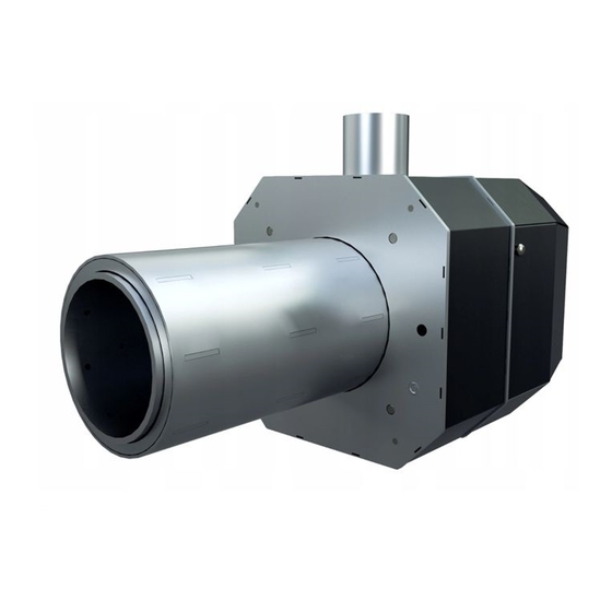
Page 36: Burner Models, Overall And Mounting Dimensions
13. Burner models, Overall and Mounting Dimensions. 13.1. ROT-POWER 4-16 kW. Fig. 16. View of burner 4-16 kW. Fig. 17. View of Burner 4-16 kW , including the insulating jacket and the mounting plate. - Page 37 13.2. ROT-POWER 5-20 kW. Fig. 18. View of burner 5-20 kW. Fig. 19. View of Burner 5-20 kW , including the insulating jacket and the mounting plate.
- Page 38 13.3. ROT-POWER 6-26 kW. Fig. 20. View of burner 6-26 kW. Fig. 21. View of burner 6-26 kW, including the insulating jacket and the mounting plate.
- Page 39 13.4. ROT-POWER 8-36 kW. Fig. 22. View of burner 8-36 kW. Fig. 23. View of burner 8-36 kW, including the insulating jacket and the mounting plate.
- Page 40 13.5. ROT-POWER 10-50kW. Fig. 24. View of burner 10-50 kW. Fig. 25. View of burner 10-50 kW, including the insulating jacket and the mounting plate.
-
Page 41: Burner's Technical Data
14. Burner's technical data. Models Parameter 4 -16 kW 5-20 kW 6-26 kW 1. Power 4-16 kW* 5-20 kW* 6-26 kW* 2. Power supply 230 VAC, 50 Hz (6 A) 3. Average power consumption 20 W 22 W 25 W 4. -
Page 42: Declaration Of Conformity
DECLARATION OF CONFORMITY Manufacturer: BTI GUMKOWSKI Sp. z o.o. Sp. k. ul. Obornicka 71, 62-002Suchy Las declares that: Pellet Burner unit, type: ROT-POWER, model: 4-16 kW, 5-20 kW, 6-26 kW, 8-36 kW, 10-50 kW meets the requirements and is compatible with: 2006/42/WE, 2006/95/WE, 2004/108/WE,... -
Page 43: Burner Installation Protocol
15. Burner Installation Protocol. Customer's Data Name: Address: Phone: E-mail: Seller's Data Company Name: Address: Phone: Fitter's Data Company Name: Address: Phone: Installation Data Burner type/model: Serial Number: Power: Year of production: Installation Date: Boiler: Year of production: Boiler power: Data on the burner settings at the time of installation Ventilation revolutions for 100% power Ventilation revolutions for 50% power... - Page 44 Hearth brightness for ignition Hearth brightness till the igniter turn off A number of hearth ignitions The results of the gas analysis Exhaust temp. MIN power Exhaust temp. MAX power emissions at MIN power emissions at MAX power Chimney Draft Excess air ratio l Efficiency I have read this Service Manual, understand its content, I accept the conditions of the warranty.
-
Page 45: Warranty
16. Warranty. 1. The manufacturer, BTI GUMKOWSKI Sp. z o.o. Sp. k., provides a 36-month guarantee for the smooth operation of the ROT-POWER Burner to the extent described in this Ser- vice Manual, starting from the date of the Burner installation (with the exception of point 2), provided that the annual payable inspection of the burner is carried out by an author- ized installer of the burner. -
Page 46: Warranty Card
Warranty Card Nr………….../……………. : ……………………… : …………..Burner type/model Serial Number ……………………… Year of production: Date of sale: …………………….. Comments: …………………………………………………………………………………… …………………………………………………………………………………………………..………………………….. manufacturer’s signature and stamp (Fills the point of sale) Maturity guarantee (subject to perform annual inspections by Warranty Terms and Conditions p.1):……………………………………………...
Need help?
Do you have a question about the ROT-POWER Series and is the answer not in the manual?
Questions and answers