Table of Contents
Advertisement
BRIDGEABLE FOUR-CHANNEL POWER AMPLIFIER
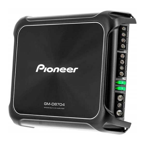
GM-D8704
GM-DX874
GM-D8704
GM-DX874
GM-D8704
PIONEER CORPORATION
PIONEER ELECTRONICS (USA) INC. P.O. Box 1760, Long Beach, CA 90801-1760, U.S.A.
PIONEER EUROPE NV Haven 1087, Keetberglaan 1, 9120 Melsele, Belgium
PIONEER ELECTRONICS ASIACENTRE PTE. LTD. 2 Jalan Kilang Barat, #07-01, Singapore 159346
PIONEER CORPORATION 2019
/XEVEW5
/XEVES
28-8, Honkomagome 2-chome, Bunkyo-ku, Tokyo 113-0021, Japan
GM-D8704/XEVUC
/XEVUC
/XEVEL5
ORDER NO.
CRT6389
/XEVUC
K-ZZZ JAN. 2019
Advertisement
Table of Contents

Summary of Contents for Pioneer GM-D8704XEVUC
- Page 1 PIONEER CORPORATION 28-8, Honkomagome 2-chome, Bunkyo-ku, Tokyo 113-0021, Japan PIONEER ELECTRONICS (USA) INC. P.O. Box 1760, Long Beach, CA 90801-1760, U.S.A. PIONEER EUROPE NV Haven 1087, Keetberglaan 1, 9120 Melsele, Belgium PIONEER ELECTRONICS ASIACENTRE PTE. LTD. 2 Jalan Kilang Barat, #07-01, Singapore 159346 PIONEER CORPORATION 2019 K-ZZZ JAN.
-
Page 2: Table Of Contents
SAFETY INFORMATION CAUTION This service manual is intended for qualified service technicians; it is not meant for the casual do-it-yourselfer. Qualified technicians have the necessary test equipment and tools, and have been trained to properly and safely repair complex products such as those covered by this manual. Improperly performed repairs can adversely affect the safety and reliability of the product and may void the warranty. -
Page 3: Service Precautions
1. SERVICE PRECAUTIONS 1.1 SAFETY PRECAUTIONS You should conform to the regulations governing the product (safety, radio and noise, and other regulations), and should keep the safety during servicing by following the safety instructions described in this manual. part and BRACKET becomes hot areas. Be careful not to burn yourself. BRACKET P.C.B TOTAL ASSY Side B... -
Page 4: Others
Put the board on a block-shaped table. Put the paper between the board and the base, and outlines these parts on it. Set the replacing parts to fit this line. Adjust the height of the replaced parts to match the board and fix it with solder. -
Page 5: Specifications
2. SPECIFICATIONS 2.1 SPECIFICATIONS For all items except the backup current, refer to the Owner's Manual. Backup current......1 mA or less 3. BASIC ITEMS FOR SERVICE 3.1 CHECK POINTS AFTER SERVICING To keep the product quality after servicing, please confirm following check points. Procedures Item to be confirmed Confirm whether the customer complaint has... -
Page 6: Diagnosis
5. DIAGNOSIS 5.1 CONNECTOR FUNCTION DESCRIPTION - GM-D8704/XEVUC, GM-DX874/XEVUC, GM-DX874/XEVEL5, GM-D8704/XEVES Front Rear - GM-D8704/XEVEW5 Front Rear 6. SERVICE MODE There is not information to be shown in this chapter. GM-D8704/XEVUC... -
Page 7: Disassembly
7. DISASSEMBLY Note: While the photograph shown is slightly different from this model in shape, the disassembly procedure is the same. - Removing the Chassis (Fig. 1) Remove 6 pcs screw and then remove the Chassis. Chassis Fig. 1 - Removing the P.C.B Total Assy (Fig. 2) BRACKET Remove 5 pcs screw and remove BRACKET. -
Page 8: Each Setting And Adjustment
Bonding Position GYL1006 8. EACH SETTING AND ADJUSTMENT There is not information to be shown in this chapter. GM-D8704/XEVUC... -
Page 9: Exploded Views And Parts List
9. EXPLODED VIEWS AND PARTS LIST OTES : Parts marked by " * " are generally unavailable because they are not in our Master Spare Parts List. The > mark found on some component parts indicates the importance of the safety factor of the part. Therefore, when replacing, be sure to use parts of identical designation. - Page 10 (2) CONTRAST TABLE GM-D8704/XEVUC, GM-DX874/XEVUC, GM-D8704/XEVEW5, GM-DX874/XEVEL5 and GM-D8704/XEVES are constructed the same except for the following: GM-D8704 GM-DX874 GM-D8704 GM-DX874 GM-D8704 Mark Description /XEVUC /XEVUC /XEVEW5 /XEVEL5 /XEVES Owner's Manual 5707000012990V 5707000012990V Not used Not used Not used Owner's Manual 5707000013000V 5707000013000V Not used Not used Not used...
-
Page 11: Exterior Section
9.2 EXTERIOR SECTION GM-D8704/XEVUC... - Page 12 (1) EXTERIOR SECTION PARTS LIST Mark No. Description Part No. Mark No. Description Part No. • • • • • Heat Sink Assy See Contrast table (2) • • • • • Sheet 1210213589000V • • • • • Sheet 1210213549000V Chassis 3200215756000V...
-
Page 13: Schematic Diagram
10. SCHEMATIC DIAGRAM P.C.B TOTAL ASSY Note: When ordering service parts, be sure to refer to " EXPLODED VIEWS AND PARTS LIST" or "ELECTRICAL PARTS LIST". JK1-C R112 R162 RCA-613F 10K-D 22/50V RCA OUTPUT A C638 R266 C114 C122 C100 R169 68N-M/100V 100N/100V-2012... -
Page 14: Pcb Connection Diagram
11.PCB CONNECTION DIAGRAM P.C.B TOTAL ASSY SIDE A POWER/PROTECT INDICATOR B_FREQ S.CONTROL B_LPF/HPF POWER B_GAIN > FUSE1 30A RCA INPUT B > FUSE1 30A RCA INPUT A RCA OUTPUT INPUT SELECT A_GAIN A_LPF/HPF A_FREQ BASS BOOST REMOTE (GM-D8704/XEVUC GM-DX874/XEVUC GM-D8704/XEVES) Capacitor NOTE FOR PCB DIAGRAMS Connector... - Page 15 P.C.B TOTAL ASSY SIDE B...
-
Page 16: Electrical Parts List
12. ELECTRICAL PARTS LIST NOTE: Parts whose parts numbers are omitted are subject to being not supplied. The part numbers shown below indicate chip components. Chip Resistor RS1/_S___J,RS1/__S___J Chip Capacitor (except for CQS..) CKS.., CCS.., CSZS..Parts marked by " * " are generally unavailable because they are not in our Master Spare Parts List. The >... - Page 17 Circuit Symbol and No. Part No. Circuit Symbol and No. Part No. RESISTORS C 135 D041220087230S C 137 (A,B,D,E) D041220087230S C 139 (A,B,D,E) D041101083240S R 38 N113138610010S R 39 N113138610010S C 140 (A,B,D,E) D041220087230S R 40 N113138622010S C 141 (A,B,D,E) D02418406C060S R 45 C120056267000S...


Need help?
Do you have a question about the GM-D8704XEVUC and is the answer not in the manual?
Questions and answers