Table of Contents
Advertisement
Advertisement
Table of Contents

Subscribe to Our Youtube Channel
Related Manuals for RTS DV 2055 Series


Summary of Contents for RTS DV 2055 Series
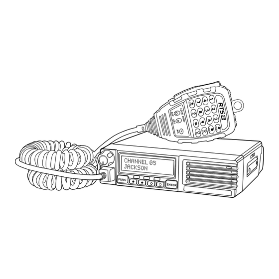
- Page 1 DV 2055/2066/2135/2400 Series Mobile Radio...
- Page 3 Precautions Thank you for choosing this vehicle transceiver, always provides high quality products, And this transceiver is Please observe the following precautions to prevent fire, no exception. As you learn how to use this transceiver, you will personal injury, and/or transceiver damage: find that is pursuing “user friendliness”.
-
Page 4: Table Of Contents
CONTENTS Emergency Function...............10 SUPPLIED ACCESSORIES/OPTIONAL ACCESSORIES ....1 Lock the keyboard ................10 Supplied Accessories ..............1 BACKGROUND OPERATIONS ............11 Optional Accessories ..............1 Squelch Setup ................11 PREPARATION ..................2 LCD Backlight ................11 Mobile Installation ................. 2 Current Voltage Display ............... 11 DC Power Cable Connection ............ -
Page 5: Supplied Accessories/Optional Accessories
SUPPLIED ACCESSORIES/OPTIONAL ACCESSORIES Supplied Accessories Optional Accessories After carefully unpacking the transceiver, identify the items listed in Programming Cloning cable Programming the table below. We recommend you keep the box and packaging for cable (PC51) shipping. (CP51) software DTMF Microphone Vehicle transceiver (QHM-04) Regulated power... -
Page 6: Preparation
PREPARATION Mobile installation To install the transceiver, select a safe, convenient location inside your vehicle that minimizes danger to your passengers and yourself while the vehicle is in motion. Consider installing the unit at an appro-priate position so that knees or legs will not strike it during sudden bra-king of your vehicle. -
Page 7: Dc Power Cable Connection
DC Power Cable Connection 4. Confirm the correct polarity of the connections, then attach the power cable to the battery terminals; red connects to the positive (+) Note: terminal and black connects to the negative (-) terminal. Locate the power input connector as close to the transceiver as • Use the full length of the cable without cutting off excess possible. -
Page 8: Fixed Station Operation
♦ Fixed Station Operation 2. Connect the transceiver's DC power connector to the connector on the DC power cable. Press the connectors firmly together until In order to use this transceiver for fixed station 1 operation, you will the locking tab clicks. need a separate 13.8 V DC power supply (not included). The recommended current capacity of your power supply is 12 A. 1. -
Page 9: Antenna Connection
Fuse Location Fuse Current Rating antenna to the transceiver before transmitting. Transceiver • All fixed stations should be equipped with a lightning arrester Supplied Accessory DC to reduce the risk of fire, electric shock, and transceiver damage. power cable Caution: Only use fuses of the specified type and rating; otherwise the transceiver could be damaged. -
Page 10: Accessories Connections
♦ Microphone Accessories Connections For voice communications, connect a microphone equipped with an ♦ External Speaker 8-pin modular plug into the modular socket on the front of the main If you plan to use an external speaker, choose a speaker with an unit. Press firmly on the plug until the locking tab clicks. -
Page 11: Getting Acquainted
GETTING ACQUAINTED Front Panel Note: This section describes only the main functions of the front panel controls. Explanations for functions not described here are provided in the appropriate sections of this instruction manual. Power switch /Volume control/Selector knob • Turn to adjust the frequency/channel while standby. • Press to scan the channels. -
Page 12: Rear Panel
Microphone Rear Panel SCAN CALL DIAL Antenna Connector NO. KEY FUNCTION • Connect an external antenna [page 5] here. When transmitting, Increase channel number or setting value. the antenna system or load should have an impedance of 50Ω. 13.8V DC Cable DOWN Decrease channel number or setting value. • Connect a 13.8V DC power source here. Use the supplied DC power cable QPL-02 [page 1]. -
Page 13: Working Mode
OPERATING BASICS WORKING MODE Channel number mode: Switching The Power On/Off Press the selector knob once to switch on the transceiver while All setup in this mode should be operated in PC software. switch off, Press and hold it for 3 seconds to switch off while standby. Adjusting The Volume After switch on the transceiver, turn the channel selector knob, When LCD displays "SET VOLUME XX" (XX shows for current volume... -
Page 14: Receiving
Receiving Emergency Function The green LED lamp flashes when the channel being called. then Press and hold key 2 seconds to start up the emergency ENTER you can hear the calling from the transmitting party. function. Once start the emergency function, the radio will sound alarm and start up transmitting, the alarm process according to its Note: pre-programmed setting. -
Page 15: Background Operations
BACKGROUND OPERATIONS LCD Backlight Background operations can be changed in any modes, and can be stored as the latest value for a long time, the operations as following: 1. Press and hold key for over 2 seconds to enter function menu. FUNC 1. -
Page 16: Microphone Operations
MICROPHONE OPERATIONS ♦ Scan channel While standby, press key to stat the channel scan frequency mode. ♦ Short call While standby, press key to transmit selected signaling (DTMF, SCAN 2-Tone, 5-Tone) CALL DIAL ♦ Input channel via Microphone keyboard While standby, input three numbers (001 -250) to switch to a desired channel. -
Page 17: Auxiliary Functions
AUXILIARY FUNCTIONS 4. D o u b l e c l i c k D V 2 0 5 5 / 2 0 6 6 / 2 1 3 5 / 2 4 0 0 s h o r t c u t o r c l i c k Cable Cloning DV2055/2066/2135/2400 in procedure index of. -
Page 18: Maintenance
MAINTENANCE General information Service note If you desire to correspond on a technical or operational problem, This product has been factory aligned and tested to specification please make your note short, complete, and to the point. Help us before shipment. In normal circumstances, the transceiver will help you by providing the following: operate in accordance with these instructions. -
Page 19: Trouble Shooting
TROUBLE SHOOTING The problems described in the following tables are commonly encountered operational malfunctions. These types of difficulties are usually caused by improper hook-up, accidental incorrect control setup, or operator error due to incomplete programming. These problems are usually not caused by circuit failure. Please review these tables and the appropriate section(s) of this instruction manual before assuming your transceiver is defective. Problem Probable Cause Corrective Action... -
Page 20: Specifications
SPECIFICATIONS Specifications Receiver (ETSI EN 300 086 standard testing ) General Wide band Narrow band HF: 33-49MHz 54-60MHz 66-88MHz Sensitivity ≤0.2μV ≤0.25μV Frequency Range VHF: 136-174MHz 245-246MHz (12dB Sinad) UHF: 400~490MHz Adjacent Channel ≥70dB ≥60dB Selectivity Number of Channels 250 channels Intermodulation ≥65dB ≥60dB...
Need help?
Do you have a question about the DV 2055 Series and is the answer not in the manual?
Questions and answers