Table of Contents
Advertisement
Available languages
Available languages
Quick Links
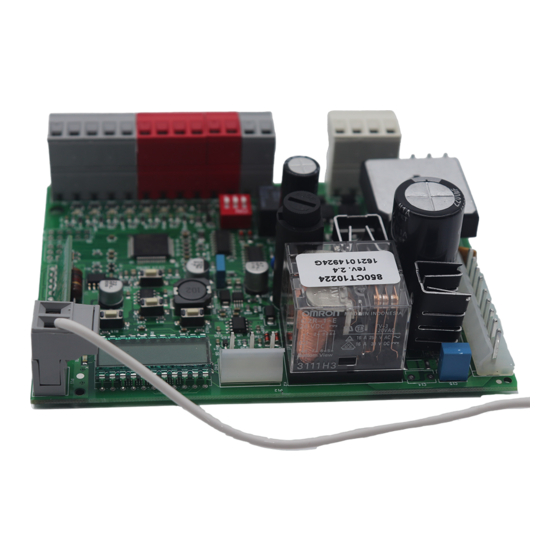
Centrale per un motore 24 Vdc, per cancello scorrevole, portone basculante o barriera
Control unit for a 24 Vdc motor, for a sliding gate, up-and-over door or barrier
Logique de commande pour un moteur 24 Vdc, pour portail coulissant, porte basculante ou barrieres
Central para un motor 24 Vdc, para puerta de corredera, portón basculante o barreras
Steuergerät für einen Motor 24 Vdc, für Schiebetor, Schwingtor oder Schrankenöffnung
Unidade para um motor 24 Vdc, para portão de correr, portão basculante ou barreira
Centrala do silnika 24 Vdc, napędzającego przesuwną bramę ogrodzeniową,
Istruzioni ed avvertenze per l'installazione e l'uso
Instructions and warnings for installation and use
Instructions et avertissements pour l'installation et l'usage
Instrucciones y advertencias para su instalación y uso
Anleitungen und Hinweise zu Installation und Einsatz
Instruções e advertências para a instalação e utilização
CT102 24
Management
System
ISO 9001:2008
www.tuv.com
ID 9105043769
uchylną bramę garażową lub szlaban
Advertisement
Chapters
Table of Contents

Related Manuals for KEY CT10224


Summary of Contents for KEY CT10224
- Page 1 Istruzioni ed avvertenze per l’installazione e l’uso Instructions and warnings for installation and use Instructions et avertissements pour l’installation et l’usage Instrucciones y advertencias para su instalación y uso Anleitungen und Hinweise zu Installation und Einsatz Instruções e advertências para a instalação e utilização CT102 24 Centrale per un motore 24 Vdc, per cancello scorrevole, portone basculante o barriera Control unit for a 24 Vdc motor, for a sliding gate, up-and-over door or barrier...
-
Page 2: Table Of Contents
INDICE Avvertenze per la sicurezza pag. 3 Introduzione al prodotto pag. 5 Descrizione della centrale pag. 5 Descrizione dei collegamenti pag. 5 Modelli e caratteristiche tecniche pag. 5 Elenco cavi necessari pag. 6 Verifiche preliminari pag. 6 Installazione del prodotto pag. -
Page 3: Avvertenze Per La Sicurezza
1 - AVVERTENZE PER LA SICUREZZA dell’automazione, scollegare immediatamente l’alimentazione elet- ATTENZIONE trica e rivolgersi al Servizio Assistenza Key Automation. L’utilizzo dell’automazione in tali condizioni può causare situazioni di pericolo; ISTRUZIONI ORIGINALI – importanti istruzioni di sicurezza. Se- guire tutte le istruzioni perchè una scorretta installazione può porta- non mettere i vari componenti dell’automazione vicino a fonti di ca-... -
Page 4: Introduzione Al Prodotto
2.1 - Descrizione della centrale tata di un display che permette una facile programmazione ed il La centrale CT10224 è il più moderno ed efficiente sistema di con- costante monitoraggio dello stato degli ingressi; inoltre la struttura trollo per i motori Key Automation per l’apertura e la chiusura elet- a menù... -
Page 5: Elenco Cavi Necessari
- Alimentazione protetta contro i cortocircuiti all’interno della centra- - Apprendimento automatico dei tempi di lavoro; le, sui motori e sugli accessori collegati; - Disattivazione degli ingressi di sicurezza tramite dip switch: non - Rilevamento degli ostacoli; occorre ponticellare i morsetti relativi alla sicurezza non installata, è sufficiente disabilitare la funzione da dip switch. -
Page 6: Installazione Del Prodotto
4 - INSTALLAZIONE DEL PRODOTTO 4.1 - Collegamenti elettrici ATTENZIONE Prima di effettuare i collegamenti verificare che la centrale non sia alimentata CONNETTORE ALIMENTAZIONI CONNETTORE MOTORE Fase alimentazione 230 Vac (120 Vac) 50-60 Hz Morsettiera collegamenti alimentazione Neutro alimentazione 230 Vac (120 Vac) 50-60 Hz Alimentazione motore Terra Alimentazione motore... -
Page 7: Visualizzazione Modalità Normale
CONNETTORE SICUREZZE E COMANDI Comune per ingressi FLASH-IND-LED FLASH Uscita lampeggiante 24Vdc (non regolato), massimo 25W Uscita IND uscita spia cancello aperto 24 Vdc non regolati 4W MAX / Uscita elettroserratura 12Vac, 15VA massimo selezionabile con parametro IN.D. Uscita luce di cortesia 24Vdc (non regolata), massimo 25W, gestibile anche via radio ON-OFF (4° canale radio, sele- zionando fC.y. - Page 8 INDICAZIONE LAMPEGGIANTE E EVENTO DESCRIZIONE LED KEY CENTRALE apertura Cancello in apertura chiusura Cancello in chiusura chiusura automatica Cancello aperto con richiusura temporizzata attiva stop in chiusura Cancello fermato nella fase di chiusura stop in apertura Cancello fermato nella fase di apertura...
-
Page 9: Autoapprendimento Della Corsa
1. Premere il pulsante DOWN (RADIO) fino a quando si accende il LED (circa 3 secondi) (>3s)-> 2. Entro 7 secondi premere un tasto del radiocomando che si vuole cancellare fino a quando il LED KEY si spe- -> gne. Rilasciare il tasto del radiocomando 3. -
Page 10: Personalizzazione Dell'impianto - Menu Base
(1s)+ 3. Premere il tasto della ricevente in corrispondenza del terzo lampeggio 4. Se la cancelllazione è andata a buon fine il LED KEY emetterà 1 lampeggio lungo MEMORIZZAZIONE A DISTANZA DI UN RADIOCOMANDO CON RADIOCOMANDO GIÀ IN MEMORIA É possibile memorizzare un trasmettitore senza accedere al ricevitore. É necessario disporre di un trasmettitore precedentemente memorizzato e seguire la procedura sottoindicata. - Page 11 PARAMETRI DESCRIZIONE DEFAULT UNITA’ Tempo richiusura automatica (0 = disabilitato) Tempo richiusura dopo il transito su PH1 (0 = disabilitato) Sensibilità su ostacolo. 0 = Massima forza di impatto 10 = Minima forza di impatto Velocità del motore in apertura 1 = minima 2 = bassa 3 = media...
-
Page 12: Collaudo E Messa In Servizio
5 - COLLAUDO E MESSA IN SERVIZIO DELL’AUTOMAZIONE Il collaudo dell impianto va eseguito da un tecnico qualificato che dalle normative, in particolare la norma EN12445 che indica i metodi deve effettuare le prove richieste dalla normativa di riferimento in di prova per gli automatismi per porte e cancelli. -
Page 13: Approfondimenti - Menu Avanzato
6 - APPROFONDIMENTI - MENU AVANZATO Il MENU AVANZATO permette di personalizzare ulteriormente l’im- LEGENDA: pianto modificando dei parametri non accessibili dal menu base SL= cancello scorrevole Per accedere al menu AVANZATO si preme e si tiene premuto per BA= barriera 5 secondi il tasto MENU OH= porta basculante Per modificare i parametri del MENU AVANZATO si procede come... - Page 14 PARAMETRI DESCRIZIONE DEFAULT UNITA’ TIPO Clearance. Permette di fermare prima della posizione di CL.E. tutto aperto; utile per non sollecitare la battuta meccanica BA/OH in apertura Uomo presente SL/BA/ de.a. 0 = disabilitato 1 = abilitato 0 = disattivata 1 = spia cancello aperto ON/OFF 2 = spia cancello aperto proporzionale - Lampeggio lento con cancello in apertura - Lampeggio veloce se cancello in chiusura...
-
Page 15: Istruzioni Ed Avvertenze Destinate
Key Automation non è però il produttore della vostra più a lungo possibile ed in completa sicurezza. Concordate con il vo- automazione, che è... - Page 16 TABLE OF CONTENTS Safety warnings pag. 19 Introduzione al prodotto pag. 21 Descrizione della centrale pag. 21 Descrizione dei collegamenti pag. 21 Modelli e caratteristiche tecniche pag. 21 Elenco cavi necessari pag. 22 Preliminary Checks pag. 22 Installing the Product pag.
- Page 17 The data and information in this manual are subject to modifi- turer or its after-sales service, or in all cases by a person with similar cation at any time, with no obligation on the part of Key Auto- qualifications, to prevent all risks;...
- Page 18 2 - INTRODUCING THE PRODUCT 2.1 - Description of the control unit All other, improper, use of the control unit is forbidden. The CT10224 The CT10224 control unit is the most modern, efficient system for has a display allowing easy programming and constant monitoring the control of Key Automation motors for the electric opening and of the input status;...
-
Page 19: Preliminary Checks
Sensitive edge 1 x cable 2 x 0,5 mm 20 m Key-switch 1 x cable 4 x 0,5 mm 20 m * If the power supply cable is more than 20 m long, it must be of larger gauge (3x2.5mm2) and a safety grounding system must be installed near the automation unit. -
Page 20: Electric Connections
4 - PRODUCT INSTALLATION 4.1 - Electrical connections WARNING Before making the connections, ensure that the control unit is not powered up POWER SUPPLY CONNECTOR MOTOR CONNECTOR Power supply live 230 Vac (120 Vac) 50-60 Hz Power supply connection terminal board Power supply neutral 230 Vac (120 Vac) 50-60 Hz Power supply motor Earth... -
Page 21: Display During Normal Operation
SAFETY AND CONTROL DEVICE CONNECTOR Common for the FLASH-IND-LED inputs FLASH Flashing light output 24Vdc (without regulation), maximum 25W IND output for gate open indicator light 24 Vdc not regulated 4W MAX / Electric lock output 12Vac, 15VA maximum selectable with parameter IN.D. - Page 22 After eliminating the cause of the alarm, to delete all errors simply The display returns to the normal screen. press the “DOWN -” key or press the SBS (STEPPING) command Press “UP“ to read the following parameters on display. DISPLAY...
-
Page 23: Autolearning Of The Travel Stroke
LIGHT ON/OFF, five times for output PRESET (button 1 = output 1, button 2 = output 2, button 3 = output 3, button 4 = output 4) 2. The KEY LED will flash a number of times equal to the number of the output selected, with 1 second pauses between flashes 3. -
Page 24: Customising The System - Basic Menu
3. Press the key of the new remote control to be memorised, holding it down for at least 3 seconds >3s 4. Press the key of the old remote control to be copied, holding it down for at least 3 seconds, to confirm and quit >3s the programming mode N.B If no commands are given for 7 seconds, the receiver automatically quits the programming mode... - Page 25 PARAMETERS DESCRIPTION DEFAULT UNIT Automatic reclosure time (0 = off) Reclosing time after transit on PH1 (0 = off) Sensitivity on obstacles 0 = Maximum impact force 10 = Minimum impact force Motor speed during opening 1 = minimum 2 = low 3 = medium 4 = high 5 = maximum...
-
Page 26: Testing And Commissioning
5 - TESTING AND COMMISSIONING THE AUTOMATION SYSTEM The system must be tested by a qualified technician, who must per- regulatory requirements, especially the EN12445 standard which form the tests required by the relevant standards in relation to the specifies the test methods for gate and door automation systems. risks present, to check that the installation complies with the relevant 5.1 Testing All system components must be tested following the procedures de-... -
Page 27: Further Details - Advanced Menu
The ADVANCED MENU allows the system to be further customised LEGENDA: by modifying parameters not accessible from the basic menu. SL= sliding gate To access the ADVANCED menu, press the MENU key and hold it BA= barrier down for 5 seconds. OH= up-and-over door To modify ADVANCED MENU parameters, proceed as described N.B. - Page 28 (setting 5 or 6); parameter FP.r. cannot be set on 2 or 3. and hold it down). A countdown should now appear: 49,48...,1 down to “don“. Release the key when finished. To use both colours of a two-colour LED strip, make the connections as explained in the CTLIGHT instructions and modify parameters FP.r.
-
Page 29: Instructions And Warnings For The
In the event of safety devices out of service arran- Thank you for choosing Key Automation S.r.l.;... - Page 30 TABLE DES MATIÈRES Consignes de sécurité page 35 Présentation du produit page 37 Description de la logique de commande page 37 Description des branchements page 37 Modèles et caractéristiques techniques page 37 Liste des câbles nécessaires page 38 Vérifications préalables page 38 Installation du produit page 39...
- Page 31 à prévenir Les données et les informations fournies dans ce guide peuvent tout risque éventuel; être modifiées par Key Automation S.r.l. à tout moment et sans obligation de préavis. si des substances liquides pénètrent à l’intérieur des pièces des com-...
-
Page 32: Présentation Du Produit
La logique de commande CT10224 est le système de commande facilement les opérations de programmation et de surveiller con- le plus moderne et le plus efficace pour les moteurs Key Automa- stamment l’état des entrées; de plus, la structure en menus simplifie tion destinés à... -
Page 33: Liste Des Câbles Nécessaires
- Alimentation protégée contre les courts-circuits à l’intérieur de la logi- - Désactivation des entrées de sécurité par commutateur DIP: il que de commande, sur les moteurs et sur les accessoires raccordés. n’est pas nécessaire de shunter les bornes relatives au dispositif de - Détection des obstacles. -
Page 34: Installation Du Produit
4 - INSTALLATION DU PRODUIT 4.1 - Branchements électriques ATTENTION Avant d’effectuer les branchements, vérifier que la logique de commande n’est pas sous tension CONNECTEUR ALIMENTATIONS CONNECTEUR MOTEUR Phase alimentation 230 Vac (120 Vac) 50-60 Hz Bornier des branchements d’alimentation Neutre alimentation 230 Vac (120 Vac) 50-60 Hz Alimentation du moteur Terre... -
Page 35: Visualisation En Mode Normal
CONNECTEUR DISPOSITIFS DE SÉCURITÉ ET COMMANDES Commun pour les entrées FLASH-IND-LED FLASH Sortie clignotant 24Vdc (non régulée), maximum 25W Sortie IND sortie voyant portail ouvert 24 Vdc non régulée 4W MAX / Sortie serrure électrique 12Vac, 15VA maximum sélectionnable avec le paramètre IN.D. - Page 36 INDICATION CLIGNOTANT ET ÉVÈNEMENT DESCRIPTION LED KEY LOGIQUE DE COMMANDE ouverture Portail en phase d’ouverture fermeture Portail en phase de fermeture fermeture automatique Portail ouvert avec refermeture temporiséeactivée arrêt en fermeture Portail arrêté dans la phase de fermeture arrêt en ouverture Portail arrêté...
-
Page 37: Autoapprentissage De La Course
ONLY OPEN, 4 fois pour la sortie LIGHT ON/OFF, 5 fois pour la sortie PRÉDÉFINIE (bouton 1 = sortie 1, bouton 2 = sortie 2, bouton 3 = sortie 3, bouton 4 = sortie 4) 2. La DEL KEY clignote le nombre de fois correspondant au numéro de la sortie sélectionnée avec une pause d’une seconde entre chaque clignotement 3. -
Page 38: Personnalisation De L'installation
1. Presser sans le relâcher la touche DOWN (RADIO) jusqu’à ce que la DEL s’allume (3 secondes environ) puis s’étei- (>3s)-> (>3s)-> gne (3 secondes environ). Relâcher la touche 2. Environ une seconde après que la touche a été relâchée, la DEL KEY commence à clignoter (1s)+ (1s)+ 3. Presser la touche du récepteur au troisième clignotement 4. - Page 39 PARAMÈTRES DESCRIPTION DÉFAUT UNITÉ Temps de la refermeture automatique (0 = désactivé) Temps de la refermeture après le transit sur PH1 (0 = désactivé) Sensibilité sur l’obstacle 0 = Force de choc maximale 10 = Force de choc minimale Vitesse du moteur en ouverture 1 = minimale 2 = lente 3 = moyenne...
-
Page 40: Réception Et Mise En Service
5 - RÉCEPTION ET MISE EN SERVICE DE L’AUTOMATISME La réception de l’installation doit être réalisée par un technicien qua- conforme aux dispositions des normes, en particulier à celles de la lifié qui doit effectuer les essais prescrits par la norme de référence norme EN12445 qui précise les méthodes d’essai à... - Page 41 6 - APPROFONDISSEMENTS- MENU AVANCÉ Le MENU AVANCÉ permet de personnaliser encore l’installation en LÉGENDE: modifiant des paramètres qui ne sont pas accessibles à l’intérieur du menu de base. SL= portail coulissant BA= barrière Pour accéder au menu AVANCÉ, presser pendant 5 secondes la OH= porte basculante touche MENU.
- Page 42 PARAMÈTRES DESCRIPTION DÉFAUT UNITÉ TYPE Clearance (Espace). Permet l’arrêt avant d’atteindre la CL.E. position complètement ouverte, de ne pas solliciter la BA/OH butée mécanique en ouverture. Commande à action maintenue SL/BA/ de.a. 0 = désactivée 1 = activée 0 = désactivé 1 = voyant portail ouvert ON/OFF 2 = voyant portail ouvert proportionnel - Clignotement lent avec portail en phase d’ouverture...
- Page 43 • en cas de rupture ou de coupure de courant: en attendant l’inter- vention de votre installateur ou le rétablissement du courant si l’in- Nous vous remercions d’avoir choisi Key Automation S.r.l et vous stallation n’est pas équipée de batteries tampon, l’automatisme peut invitons à...
- Page 44 ÍNDICE Advertencias para la seguridad pág. 51 Introducción al producto pág. 53 Descripción de la central pág. 53 Descripción de las conexiones pág. 53 Modelos y características técnicas pág. 53 Lista de los cables necesarios pág. 54 Controles preliminares pág. 54 Instalación del producto pág.
- Page 45 Para la seguridad de las personas es importante re- mentación eléctrica y contacte con el Servicio de Asistencia Key spetar las siguientes instrucciones de seguridad. Guarde estas Automation. Utilizar el automatismo en dichas condiciones podría instrucciones.
-
Page 46: Introducción Al Producto
2.1 - Descripción de la central La central CT10224 incorpora una pantalla que permite progra- La central CT10224 es el sistema de control más moderno y eficien- mar fácilmente y monitorizar de manera constante las entradas; te de los motores Key Automation para la apertura y el cierre eléc- además, la estructura de menú... -
Page 47: Lista De Los Cables Necesarios
- Alimentación protegida contra los cortocircuitos en el interior de la - Desactivación de las entradas de seguridad mediante dip switch: central, en los motores y en los accesorios conectados. no es necesario puentear los bornes relativos al dispositivo de segu- - Detección de los obstáculos. -
Page 48: Instalación Del Producto
4 - INSTALACIÓN DEL PRODUCTO 4.1 - Conexiones eléctricas ATENCIÓN Antes de realizar las conexiones, compruebe que la central no esté alimentada CONECTOR ALIMENTACIONES CONECTOR MOTOR Fase alimentación 230 Vac (120 Vac) 50-60 Hz Regleta de conexiones alimentación Neutro alimentación 230 Vac (120 Vac) 50-60 Hz Alimentación motor Tierra Alimentación motor... -
Page 49: Visualización Modo Normal
CONECTOR DISPOSITIVOS DE SEGURIDAD Y MANDOS Común para las entradas FLASH-IND-LED FLASH Salida luz intermitente 24Vdc (no regulado), máximo 25W Salida IND salida indicador luminoso puerta abierta 24 Vdc no regulados 4 W MÁX. / Salida electrocerradura 12Vac, 15VA máximo seleccionable con parámetro IN.D. - Page 50 INDICACIÓN LUZ INTERMITENTE Y LED EVENTO DESCRIPCIÓN KEY CENTRAL DE MANDO apertura Puerta abriéndose cierre Puerta cerrándose cierre automático Puerta abierta con cierre temporizado activo parada durante el cierre Puerta detenida durante el cierre parada durante la apertura Puerta detenida durante la apertura abierta Puerta completamente abierta sin cierre automático...
-
Page 51: Autoaprendizaje De La Carrera
4 veces para la salida LIGHT ON/OFF, 5 veces para la salida PRECONFIGURADO (bóton 1 = salida 1, bóton 2 = salida 2, bóton 3 = salida 3, bóton 4 = salida 4) 2. El LED KEY realiza un número de destellos correspondiente a la salida seleccionada, con un intervalo de pausa de 1 segundo 3. -
Page 52: Personalización Del Sistema - Menú Básico
1. Presione y mantenga presionado el pulsador DOWN (RADIO) hasta que se encienda el LED (3 segundos aprox.) y (>3s)-> (>3s)-> luego se apague (3 segundos aprox.). Suelte el pulsador 2. Transcurrido 1 segundo después de haber soltado el pulsador, el LED KEY comenzará a destellar (1s)+ (1s)+ 3. Presione el pulsador del receptor en el tercer destello 4. - Page 53 PARÁMETROS DESCRIPCIÓN DEFECTO MÍN. MÁX. UNIDAD Tiempo cierre automático (0 = inhabilitado) Tiempo cierre después de tránsito su PH1 (0 = inhabilitado) Sensibilidad sobre el obstáculo 0 = Fuerza de impacto máxima 10 = Fuerza de impacto mínima Velocidad del motor durante la apertura 1 = mínima 2 = lenta 3 = mediana...
-
Page 54: Ensayo
5 - ENSAYO Y PUESTA EN SERVICIO DEL AUTOMATISMO El ensayo del sistema debe ser llevado a cabo por un técnico ca- el cumplimiento de lo previsto por las normativas, especialmente la lificado que debe realizar las pruebas requeridas por la normativa Norma EN 12445 que indica los métodos de ensayos para los auto- de referencia de acuerdo con los riesgos presentes, comprobando matismos de puertas motorizadas. - Page 55 6 - DESCRIPCIÓN DETALLADA - MENÚ AVANZADO El MENÚ AVANZADO permite personalizar aún más el sistema mo- LEYENDA: dificando algunos parámetros a los que no se puede acceder desde el menú básico SL= puerta corredera BA= barrera Para acceder al menú AVANZADO, presione y mantenga presiona- OH= puerta basculante do durante 5 segundos el pulsador MENU Nota: algunas funciones/visualizaciones por defecto pueden variar...
- Page 56 PARÁMETROS DESCRIPCIÓN DEFECTO MÍN MÁX UNIDAD TIPO Clearance. Permite detener antes de la posición de todo CL.E. abierto; útil para no sobrefatigar el tope mecánico de BA/OH apertura Hombre presente SL/BA/ de.a. 0 = inhabilitado 1 = habilitado 0 = desactivada 1 = indicador luminoso puerta abierta ON/OFF 2 = indicador luminoso puerta abierta proporcional - Destello lento con puerta abriéndose...
- Page 57 Key Automation aconseja un servicio cada 6 meses para un uso des, seguro y duradero y, sobre todo, realizado correctamente y de doméstico normal, pero dicha frecuencia puede variar en función...
- Page 58 INHALTSVERZEICHNIS Sicherheitshinweise Einführung in das Produkt S. 69 S. 69 Beschreibung des Steuergerätes S. 69 Beschreibung der Anschlüsse S. 69 Modelle und technische Eigenschaften S. 70 Liste benötigter Kabel Vorabkontrollen S. 70 Produktinstallation S. 71 Elektrische Anschlüsse S. 71 Anzeige Normalmodus S.
-
Page 59: Sicherheitshinweise
Handbuch zu beachten. Dieses Produkt kann nicht als ausreichendes System für den Bei Zweifel jeglicher Art die Installation abbrechen und ggf. den Key Einbruchsschutz angesehen werden. Wenn Sie sich ausreichend Automation Kundendienst zur Klärung kontaktieren. -
Page 60: Einführung In Das Produkt
2 - EINFÜHRUNG IN DAS PRODUKT 2.1 - Beschreibung des Steuergerätes Das CT10224 ist mit einem Display ausgestattet, das eine einfache Das Steuergerät CT10224 ist das modernste und effizienteste Be- Programmierung und kontinuierliche Überwachung des Status der triebssystem für die Motoren von Key Automation zum elektrischen Eingänge erlaubt. -
Page 61: Liste Benötigter Kabel
- Gegen Kurzschlüsse im Steuergerät, an den Motoren und am an- - Ausschaltung der Sicherheitseingänge durch Dip Switch: Die geschlossenen Zubehör geschützte Versorgung. Klemmen der nicht installierten Sicherheitsvorrichtungen müssen - Hinderniserkennung. nicht überbrückt werden; es reicht aus, die Funktion mit Dip Switch - Automatisches Erlernen der Arbeitszeit. -
Page 62: Produktinstallation
4 - PRODUKTINSTALLATION 4.1 - Stromanschlüsse ACHTUNG Vor dem Anschluss sicherstellen, dass die Stromzufuhr des Steuergerätes abgeschaltet ist. STROMVERBINDER MOTORVERBINDER Phase 230 Vac (120 Vac) 50-60 Hz Klemmenleiste Versorgungsanschlüsse Nullleiter 230 Vac (120 Vac) 50-60 Hz Spannungsversorgung Motor Erde Spannungsversorgung Motor Spannungsversorgung Encoder WÄHLSCHALTER DIP SWITCH Encodersignal... -
Page 63: Anzeige Normalmodus
VERBINDER FÜR SICHERHEITSVORRICHTUNGEN UND BEDIENELEMENTE Gemeinsamer Leiter für Eingänge FLASH-IND-LED FLASH Ausgang Blinkleuchte 24Vdc (ungeregelt), maximal 25W Ausgang IND Ausgang Kontrolllampe Tor geöffnet 24 Vdc ungeregelt 4W MAX / Ausgang Elektroschloss 12Vac, 15VA maximal wählbar über Parameter IN.D. Ausgang zusätzliche Beleuchtung 24Vdc (ungeregelt), maximal 25W, Bedienung auch per Funk ON-OFF (4. Funkkanal dazu fC.y. - Page 64 ANZEIGE BLINKLICHT UND EREIGNIS BESCHREIBUNG KEY-LED DES STEUERGERÄTS Öffnung Tor in Öffnung Schließung Tor in Schließung Automatische Schließung Tor geöffnet mit zeitgesteuertem Wiederschließen aktiviert Stopp bei Schließung Tor in Schließphase angehalten Stopp bei Öffnung Tor in Öffnungsphase angehalten geöffnet Tor vollständig geöffnet ohne automatisches Wiederschließen geschlossen Tor vollständig geschlossen...
-
Page 65: Einlernen Des Laufs
Ausgang LIGHT ON/OFF, 5 mal für Ausgang VOREINGESTELLT (Taste 1 = Ausgang 1, Taste 2 = Ausgang 2, Taste 3 = Ausgang 3, Taste 4 = Ausgang 4) 2. Die LED KEY blinkt mit der Anzahl, die dem gewählten Ausgang entspricht, unterbrochen von einer Pause von 1 Sekunde 3. -
Page 66: Benutzerdefinierte Einrichtung Der Anlage
1. Die Taste DOWN (RADIO) drücken und gedrückt halten, bis die LED (ca. 3 Sekunden) aufleuchtet und dann (>3s)-> (>3s)-> erlischt ( ca. 3 Sekunden). Die Taste loslassen 2. Ca. 1 Sekunde nach dem Loslassen der Taste beginnt die LED KEY zu blinken (1s)+ (1s)+ 3. Die Taste des Empfängers beim dritten Blinken betätigen 4. - Page 67 PARAMETER BESCHREIBUNG STANDARD EINHEIT Automatische Wiederschließzeit (0 = deaktiviert) Wiederschließzeit nach Durchfahrt auf PH1 (0 = deaktiviert) Empfindlichkeit gegenüber Hindernis 0 = Höchste Aufprallkraft 10 = Mindeste Aufprallkraft Geschwindigkeit des Motors bei Öffnung 1 = minimal 2 = niedrig 3 = mittel 4 = hoch 5 = maximal Geschwindigkeit des Motors bei Öffnung während der...
-
Page 68: Test Und Inbetriebnahme
5 - TEST UND INBETRIEBNAHME DER AUTOMATION Die Endabnahme der Anlage muss von einem qualifizierten Tech- ausführt und die Einhaltung der Anforderungen prüft. Besonders zu niker durchgeführt werden, der die durch die einschlägigen Bestim- berücksichtigen ist hierbei die Norm EN12445, welche die Prüfver- mungen je nach bestehenden Gefahren vorgesehenen Prüfungen fahren für Automationen an Türen und Toren festlegt. -
Page 69: Vertiefung - Erweitertes Menü
6 - VERTIEFUNG - ERWEITERTES MENÜ Das ERWEITERTE MENÜ erlaubt durch Parameteränderungen, die ZEICHENERKLÄRUNG: nicht im GRUNDMENÜ möglich sind, eine weitere Anpassung der Anlage an die persönlichen Bedürfnisse. SL= Schiebetor BA= Schranke Für den Zugriff auf das ERWEITERTE Menü die Taste MENU 5 OH= Schwingtor Sekunden lang drücken. - Page 70 PARAMETER BESCHREIBUNG STANDARD MIN MAX EINHEIT Clearance. Ermöglicht das Anhalten vor der ganz offenen CL.E. stellung zur schonung des mechanischen Anschlags bei BA/OH der Öffnung. Totmann SL/BA/ de.a. 0 = deaktiviert 1 = aktiviert 0 = deaktiviert 1 = Kontrollleuchte Tor geöffnet ON/OFF 2 = Kontrollleuchte Tor geöffnet proportional - Langsames Blinken bei öffnendem Tor - Schnelles Blinken bei schließendem Tor...
- Page 71 Schlüssel, der zum Lieferumfang gehört, wie eine nicht automatisierte Öffnung arbeiten. Bei nicht funktionierenden Wir danken Ihnen, dass Sie Key Automation S.r.l. gewählt haben, Sicherheitsvorrichtungen muss schnellstmöglich die Reparatur der und laden Sie ein, für weitere Informationen unsere Internetseite Automation veranlasst werden;...
- Page 72 ÍNDICE Avisos sobre a segurança pág. 83 Informações sobre o produto pág. 85 Descrição da unidade pág. 85 Descrição das ligações pág. 85 Modelos e características técnicas pág. 85 Lista de cabos necessários pág. 86 Controlos preliminares pág. 86 Instalação do produto pág.
- Page 73 1 - AVISOS SOBRE A SEGURANÇA tactar o serviço de Assistência Key Automation. A utilização da auto- ATENÇÃO mação nestas condições pode causar situações de perigo. INSTRUÇÕES ORIGINAIS – instruções importantes de segu- Manter os componentes da automação afastados do calor e de cha- rança.
-
Page 74: Informações Sobre O Produto
2.1 - Descrição da unidade A CT10224 está equipada com um ecrã que permite programar fa- A unidade CT10224 é o mais moderno e eficiente sistema de con- cilmente e monitorizar constantemente o status das entradas; além trolo para os motores Key Automation para a abertura e o fecho disso, a estrutura em menu permite configurar de forma simples os elétrico de portões de correr e basculantes e barreiras de controlo... -
Page 75: Lista De Cabos Necessários
- Alimentação protegida contra curto-circuitos dentro da unidade, - Desativação das entradas de segurança através de comutador nos motores e nos acessórios ligados. DIP: não é necessário ligar diretamente os bornes relativos à segu- - Deteção dos obstáculos. rança não instalada, basta desabilitar a função no comutador DIP. - Autoaprendizagem dos tempos de trabalho. -
Page 76: Instalação Do Produto
4 - INSTALAÇÃO DO PRODUTO 4.1 - Ligações elétricas ATENÇÃO Antes de fazer as ligações, verificar se a unidade não está ligada à alimentação elétrica. CONECTOR DAS ALIMENTAÇÕES CONECTOR DO MOTOR Fase da alimentação 230 Vac (120 Vac) 50-60 Hz Placa de bornes ligações alimentação Neutro da alimentação 230 Vac (120 Vac) 50-60 Hz Alimentação do motor... -
Page 77: Visualização No Modo Normal
CONECTOR SEGURANÇAS E COMANDOS Comum para entradas FLASH-IND-LED FLASH Saída da luz de sinalização 24Vdc (não regulado), máximo 25W Saída IND saída do led de portão aberto 24 Vdc não regulado 4W MAX / Saída da fechadura elétrica 12Vac, 15VA máximo selecionável com parâmetro IN.D. - Page 78 INDICAÇÃO LUZ DE SINALIZAÇÃO E EVENTO DESCRIÇÃO LED KEY UNIDADE abertura O portão está a abrir fecho O portão está a fechar fecho automático Portão aberto com fecho temporizado ativo paragem durante o fecho Portão parado durante o fecho paragem durante a abertura Portão parado durante a abertura...
-
Page 79: Autoaprendizagem Do Curso
1. Premir a tecla DOWN até quando se acender o LED (cerca de 3 segundos) (>3s)-> 2. Dentro de 7 segundos premir uma tecla do radiocomando que se deseja eliminar até quando o LED KEY se -> apagar. Libertar a tecla do radiocomando 3. -
Page 80: Personalização Do Sistema - Menu Básico
(>3s)-> (>3s)-> depois se apagar (cerca de 3 segundos). Libertar a tecla 2. Cerca de 1 segundo após libertar a tecla, o LED KEY fica intermitente (1s)+ (1s)+ 3. Premir a tecla do recetor na altura do terceiro sinal intermitente 4. - Page 81 PARÂMETROS DESCRIÇÃO DEFAULT MÍN MÁX UNIDADE Tempo fecho automático (0 = desabilitado) Tempo fecho após passagem em PH1 (0 = disabilitato) Sensibilidade em obstáculo 0 = Força de impacto máxima 10 = Força de impacto mínima Velocidade do motor durante a abertura 1 = mínima 2 = baixa 3 = média...
-
Page 82: Ensaio E Colocação Em Serviço
5 - ENSAIO E COLOCAÇÃO EM SERVIÇO O ensaio do sistema deve ser feito por um técnico qualificado que mas, sobretudo a norma EN 12445 que estabelece os métodos de deve efetuar os testes previstos pela norma de referência de acordo ensaio dos automatismos para portas e portões. - Page 83 6 - APROFUNDAMENTOS - MENU AVANÇADO O MENU AVANÇADO permite personalizar ainda mais o sistema LEGENDA: modificando os parâmetros não acessíveis a partir do menu básico. SL= portão de correr Para aceder ao menu AVANÇADO, é necessário premer e manter BA= barreira de controlo de acessos premido durante 5 segundos a tecla MENU.
- Page 84 PARÂMETROS DESCRIÇÃO DEFAULT MÍN MÁX UNIDADE TIPO Clearance. Permite parar antes da posição de tudo aberto; CL.E. BA/OH serve para não solicitar o batente mecânico na abertura Homem morto SL/BA/ de.a. 0 = desabilitado 1 = habilitado 0 = desativado 1 = led de portão aberto ON/OFF 2 = led de portão aberto proporcional - Intermitência lenta durante a abertura do portão...
- Page 85 Key Automation recomenda uma intervenção a cada 6 meses seguro e fiável no tempo, e feito sobretudo como manda a lei, de para uma utilização doméstica normal, mas este período pode va-...
- Page 86 SPIS TREŚCI Uwagi dotyczące bezpieczeństwa str. 99 Informacje wstępne o produkcie str. 101 Opis centrali str. 101 Opis podłączeń str. 101 Modele i parametry techniczne str. 101 Wykaz niezbędnych przewodów elektrycznych str. 102 Kontrole wstępne str. 102 Montaż produktu str. 103 Podłączenia elektryczne str.
- Page 87 INSTRUKCJA ORYGINALNA – ważne zalecenia dotyczące elementów układu automatyki, odłączyć niezwłocznie zasilanie bezpieczeństwa. W celu zapewniania bezpieczeństwa osób elektryczne i skontaktować się z serwisem technicznym Key Au- należy stosować się do poniższych zaleceń. Zachować tomation. Użytkowanie automatyki w powyższej sytuacji stanowi niniejszą...
-
Page 88: Opis Centrali
2 - INFORMACJE OGÓLNE 2.1 - Opis centrali Zabrania się używania centrali niezgodnie z przeznaczeniem. Centrala CT10224 jest najnowocześniejszym i najbardziej wydajnym Centrala CT10224 wyposażona jest w wyświetlacz ułatwiający systemem sterowania silnikami Key Automation, służącymi do czynności programowania oraz umożliwiający nieustanne monito- elektrycznego otwierania i zamykania przesuwnych bram ogrodze- rowanie stanu wejść. -
Page 89: Wykaz Niezbędnych Przewodów Elektrycznych
- Sposób zasilania chroniący przed zwarciem w obrębie centrali, - Dezaktywowanie wejść bezpieczeństwa przy użyciu przełącznika. w silnikach oraz w podłączonych urządzeniach dodatkowych. Brak konieczności montowania zworek na wejściach przeznaczony- - Wykrywanie przeszkód. ch dla niezamontowanych zabezpieczeń; wystarczy dezaktywować - Automatyczne programowanie czasów pracy. funkcję... -
Page 90: Montaż Produktu
4 - MONTAŻ PRODUKTU 4.1 - Podłączenia elektryczne UWAGA przed przystąpieniem do wykonywania podłączeń sprawdzić, czy do centrali nie jest doprowadzone zasilanie. GNIAZDA ZASILANIA GNIAZDO SILNIKA Faza zasilania 230 Vac (120 Vac) 50-60 Hz Listwa zaciskowa do podłączenia zasilania Zero zasilania 230 Vac (120 Vac) 50-60 Hz Zasilania silnika Uziemienie Zasilania silnika... -
Page 91: Wyświetlanie Normalnego Trybu Pracy
GNIAZDO URZĄDZEŃ ZABEZPIECZAJĄCYCH I STEROWANIA Wspólne gniazdo dla wejść FLASH-IND-LED FLASH Wyjście lampy ostrzegawczej 24Vdc (nieregulowane), maksymalnie 25W Wyjście IND wyście kontrolki otwartej bramy 24 Vdc nieregulowane 4W MAX / Wyjście elektrozamka 12Vac, 15VA maksymalnie wybierany jest za pomocą parametru IN.D. - Page 92 WSKAZANIA LAMPY OSTRZEGAWCZEJ ORAZ ZDARZENIE OPIS LED KEY CENTRALE otwieranie Brama otwarta zamykanie Brama zamknięta zamykanie automatyczne Brama otwarta z zamykaniem czasowym aktywna stop w trakcie zamykania Brama zatrzymana w fazie zamykania stop w trakcie otwierania Brama zatrzymana w fazie otwierania Brama całkowicie otwarta bez ponownego...
-
Page 93: Automatyczne Programowanie Przebiegu
(przycisk 1 = wyjścia 1, przycisk 2 = wyjścia 2, przycisk 3 = wyjścia 3, przycisk 4 = wyjścia 4) 2. Znajdująca się LED KEY błyska taką liczbę razy, jaka odpowiada numerowi wybranego wyjścia; błyski przed- zielane są pauzą trwającą 1 s 3. -
Page 94: Indywidualne Dostosowanie Urządzenia - Menu Podstawowe
1. Wcisnąć i przytrzymać przycisk DOWN (RADIO) do momentu zaświecenia się diody LED (ok. 3 sekundy) a (>3s)-> (>3s)-> potem jej zgaśnięcia (ok. 3 sekundy). Zwolnić przycisk 2. Po upływie ok. 1 sekundy od zwolnienia przycisku, dioda LED KEY zaczyna migać (1s)+ (1s)+ 3. Wcisnąć przycisk odbiornika w trakcie trzeciego mignięcia 4. - Page 95 USTAWIENIA PARAMETRY OPIS MAKS JEDNOSTKA DOMYŚLNE Czas ponownego automatycznego zamknięcia (0 = nieaktywny) Czas ponownego zamknięcia po wykonaniu przebiegu na PH1 (0 = nieaktywny) Czułość wykrywania przeszkody 0 = maksymalna siła uderzenia 10 = minimalna siła uderzenia Prędkość silnika podczas otwierania 1 = minimalna 2 = mała 3 = średnia...
-
Page 96: Odbiór Techniczny
5 - ODBIÓR TECHNICZNY ORAZ ODDANIE DO Odbiór techniczny instalacji powinien zostać wykonany przez wykwa- wymogi właściwych przepisów. W szczególności dotyczy to normy lifikowanego technika, który zobowiązany jest do przeprowadzenia EN 12445, która określa metody badań kontrolnych automatyki testów, określonych przez odpowiednie przepisy w zależności od bram garażowych i ogrodzeniowych. - Page 97 6 - ZAGADNIENIA ROZSZERZONE - MENU ZAAWANSOWANE MENU ZAAWANSOWANE umożliwia dalsze indywidualne dopaso- LEGENDA: wanie instalacji, poprzez zmianę parametrów niedostępnych w menu podstawowym. SL = brama przesuwna BA = szlaban Aby uzyskać dostęp do menu ZAAWANSOWANEGO, wcisnąć OH = brama uchylna i przytrzymać...
- Page 98 USTAWIENIA PARAMETRY OPIS MIN MAKS JEDNOSTKA TYP DOMYŚLNE SL/BA/ tC.Y. Czas świecenia się świateł odprowadzających Usunięcie. Pozwala na zatrzymanie przed pozycją CL.E. całkowitego otwarcia; ma na celu nie dopuścić do BA/OH kontaktu z ogranicznikiem mechanicznym. Obecność człowieka SL/BA/ de.a. 0 = nieaktywna 1 = aktywna 0 = nieaktywna 1 = kontrolka brama otwarta ON/OFF...
- Page 99 • Ręczne odblokowanie i przesunięcie. Przed przystąpieniem do bram ogrodzeniowych i garażowych, drzwi automatycznych, rolet wykonania tej czynności należy upewnić się, że skrzydło bramy po- oraz szlabanów parkingowych i drogowych. Key Automation nie jest zostaje nieruchome. jednakże wykonawcą Państwa całościowego systemu automatyki, który stanowi wynik analizy, oceny, doboru materiałów i wykonania...
- Page 100 UWAGI...
- Page 101 UWAGI...
- Page 102 UWAGI...
- Page 103 DICHIARAZIONE DI INCORPORAZIONE DI QUASI-MACCHINA DECLARATION OF INCORPORATION OF PARTLY COMPLETED MACHINERY Il sottoscritto Nicola Michelin, Amministratore Delegato dell’azienda The undersigned Nicola Michelin, General Manager of the company Key Automation srl, Via Alessandro Volta, 30 - 30020 Noventa di Piave (VE) – ITALIA dichiara che il prodotto tipo: declares that the product type: CT10224 Centrale di comando 1 motore 24 Vdc con ricevente radio 433,92 Mhz integrata 24 Vdc Control unit for 1 motor with 433,92 Mhz built‐in radio receiver ...
- Page 104 Key Automation S.r.l. Via A. Volta 30 - 30020 Noventa di Piave (VE) T. +39 0421.307.456 - F. +39 0421.656.98 Instruction version info@keyautomation.it - www.keyautomation.it 580ISCT10224 REV.07...
Need help?
Do you have a question about the CT10224 and is the answer not in the manual?
Questions and answers