
Related Manuals for FEC Handheld Nutrunner HFC3000


Summary of Contents for FEC Handheld Nutrunner HFC3000
- Page 1 HFC3000E-HW-2 January 2019...
- Page 2 Copyright © 2017 FEC AUTOMATION SYSTEMS. All Rights Reserved.
- Page 3 Introduction Thank you for purchasing our Handheld Nutrunner. This instruction manual describes the procedures for installation, and handling, and actions to be taken in case of any failure. ◆ This instruction manual shall be delivered to the end user who operates the equipment. ◆...
- Page 4 5. If the cause of a malfunction is an act of God or other disaster. The scope of this warranty is limited to the main body of our equipment and damage induced by a malfunction of this equipment shall be excluded from the warranty. See FEC Website for full Warranty information: https://www.fec-usa.com/rma_repair.htm...
- Page 5 Safety Precautions Read all instructions before operating the equipment in order to use this equipment safely and correctly. Prior to use, read this instruction manual carefully and fully understand the equipment functions, safety precautions and instructions. Safety precautions in this manual are ranked as [Warning] or [Caution]. To prevent danger to the user and other persons as well as property damage, the instructions that must be fully observed are marked with the symbols below.
- Page 6 Safety Precautions Warning Do not remove the motors and gear cases of tools. The tool output spindle may rotate and cause injury. Do not repair, disassemble, or modify the equipment. Failure to observe this instruction may cause injury, electric shock, fire, or malfunction. Never operate the equipment where it is exposed to water or near corrosive atmosphere and flammable gases.
- Page 7 Safety Precautions Transportation/Storage Caution Transport the equipment properly according to its weight. Failure to observe this instruction may cause injury and malfunction. The conditions when transporting the equipment by ship are as below. ◆ Ambient temperature: -5°C ~ +55°C (Avoid freezing) ◆...
- Page 8 Safety Precautions Installation/Wiring Caution Install the controller using the specified screws. Failure to observe this instruction may cause malfunction. Use the specified combination of the tool and the controller. Failure to observe this instruction may cause fire and malfunction. The power input parts must be provided with safety measures such as breakers and circuit protectors.
- Page 9 Safety Precautions Operation/Adjustment Caution Never operate the equipment with wet hands. Failure to observe this instruction may cause electric shock. Use the equipment under the following conditions. ◆Ambient temperature: 0°C~+45°C (Avoid freezing) ◆Ambient humidity: 90% RH or lower (Avoid moisture) ◆Atmosphere: Indoors (Avoid direct sunlight) No corrosive gases or flammable gases No oil mist, dust, water, salt, iron powder...
-
Page 10: Table Of Contents
Table of Contents Chapter 1 Outline 1-1 How to Use This Instruction Manual 1-2 Features 1-3 Safety Precautions Chapter 2 Specifications 2-1 System Specifications 2-1-1 Duty Cycle Calculation 2-1-2 Controller Specifications 2-2 Performance 2-2-1 Fastening Performance 2-2-2 Controller 2-2-3 List of Tools 2-3 Functions 2-3-1 Main Functions 2-3-2 Fastening Methods... - Page 11 Table of Contents 4-8 Ethernet Interface 4-25 4-8-1 TCP/IP Setup Procedure 4-26 4-8-2 TCP/IP Setup Procedure (HFC3000 User Console Software) 4-29 Chapter 5: Power Up and Operational Tests 5-1 Items to be Checked Before Power On 5-2 Items to be Checked When Powering On the Equipment 5-3 Input Initial Setting Data Chapter 6 Fastening Operation 6-1 Changing between RUN and PROGRAM Modes...
- Page 12 Table of Contents Chapter 8 Options 8-1 CompactFlash (CF) Card 8-1-1 Summary 8-1-2 Selection Criteria 8-1-3 CF Access LED 8-1-4 Storing Data in the CF Memory Card 8-1-5 Data Storage Flow 8-1-6 Checking the capacity of CF Memory Card 8-1-7 Formatting the CF Memory Card 8-2 Expansion RS232C Interface 8-3 ID Data Input Setting 8-10...
- Page 13 Revision History Revision Manual No. Content of revision Page date (SupportingV1.000) – Release from DDK (S0140185-C) Jan, 2017 HFC3000E-HW-1 1 Edition Edition (supporting V1.130) – Release from DDK (S0140185-G) Majority Jan. 2019 HFC3000E-HW-2 English updated 5-3, 6-7 June 2019 HFC3000E-HW-2 Added note concerning powering on with P-OFF remaining in display Manual Numbering Convention HFC3000E-HW-1...
- Page 14 Notes...
- Page 15 Chapter 1 Outline Chapter 1 Outline PAGE 1-1...
-
Page 16: How To Use This Instruction Manual
Chapter 1 Outline 1-1 How to Use This Instruction Manual This manual describes the system structure, specifications, handling method, etc., of the Handheld Nutrunner System. These are described in the following order in this manual: Chapter Items Contents Chapter 1 Outline Description of functions Chapter 2... -
Page 17: Features
Chapter 1 Outline 1-2 Features The Handheld Nutrunner is a flexible fastening tool equipped with a compact, high-performance servomotor developed especially for this product. Like the usual high-performance nutrunner system, it is designed to accommodate various tool models and provide useful functions for error proofing, data management, data communication, etc. - Page 18 Chapter 1 Outline ☆ Fastening Result Record Fastening resultant data is saved in a nonvolatile controller memory (approx. 12,000 cycles of data). 100 sets of torque curve data is stored in volatile memory (RAM). 100 sets of Reject curve data is stored in nonvolatile memory. The fastening resultant data and the Reject curve data are therefore preserved even if the power is turned off.
-
Page 19: Safety Precautions
Chapter 1 Outline 1-3 Safety Precautions To ensure the most effective and extended use of all equipment, adhere to the following precautions: ☆ Handling of tool Tools can generate a large amount of torque during operation, and the reaction force is applied to the Operator or mounting area of the tool. - Page 20 Chapter 1 Outline ☆ Cleaning Do not use any organic solvents, such as thinner, to clean a Controller or a tool. The solvent could melt the surface paint, display overlay or penetrate inside and cause damage. A cloth dampened with alcohol or warm water should be used to lightly wipe the components. ☆...
- Page 21 Chapter 2 Specifications Chapter 2 Specifications PAGE 2-1...
-
Page 22: System Specifications
Chapter 2 Specifications 2-1 System Specifications Single-phase 100V AC~240V AC ±10% Voltage (5m cable for 100-120VAC provided as accessory) Power Source Frequency 50/60Hz No vibration must be applied directly to the controller. Installation environment Forced-cooling equipment or heating equipment is required when using the Controller outside the following operating range. -
Page 23: Performance
Chapter 2 Specifications 2-2 Performance 2-2-1 Fastening Performance From 1/2 ~ Calibration torque 3σ/: 5% or less From 1/4 ~ 1/2 Calibration torque Torque Accuracy 3σ/ : 6% or less (Accuracy in the case of in-house standard fastening. *May differ according to application.) Angle Display (minimum) 0.1 degree Angle (internal control) -
Page 24: List Of Tools
Tool Shape S:Straight A:Angle T:T-Type P:Pistol L:L-Type D:Driver Motor Type 50:45W 120:120W 80:70W 81: Maximum Torque For any tools not indicated in the table, please contact FEC Maximum Minimum Maximum Maximum Tool Rotation Rotation Torque Rate Tool Model Controller Speed Speed [N・m]... - Page 25 Chapter 2 Specifications 1800 99.999 HFC-B016 / HFC-B024A HFT-010M50-S1 10.00 1000 99.999 HFC-B016 / HFC-B024A HFT-025M80-S1 25.00 99.999 HFC-B016 / HFC-B024A HFT-055M80-S 55.00 999.99 HFC-B016 / HFC-B024A HFT-080M80-S 80.0 1000 99.999 HFC-B016 / HFC-B024A HFT-015M50-P 15.00 99.999 HFC-B016 / HFC-B024A HFT-060M80-T 60.0 99.999 HFC-B016 / HFC-B024A...
-
Page 26: Functions
Chapter 2 Specifications 2-3 Functions 2-3-1 Main Functions (1) Fastening Function The HFC3000 SYSTEM is capable of the following fastening methods. 1. Torque method: Angle monitor, Torque rate monitor, 1/2/3 step fastening 2. Angle method: Torque monitor, Torque rate monitor, 1/2/3 step fastening (2) Self-Check Function When control power is turned “ON”, the values of the torque tranducer ZERO voltage and CAL voltage are acquired (these are reference values used for fastening). -
Page 27: Fastening Methods
Chapter 2 Specifications 2-3-2 Fastening Method (1) Torque Method (Angle Monitor) Fastening is performed up to a preset Standard Torque. The fastening operation is performed with the preset torque as the target, and high limit/low limit judgment of the angle value is enabled. The number of fastenings steps is selectable among 1, 2, and 3 steps. - Page 28 Chapter 2 Specifications (Blank Page) PAGE 2-8...
- Page 29 Chapter 3 Sysytem Description Chapter 3 System Description PAGE 3-1...
-
Page 30: Controller
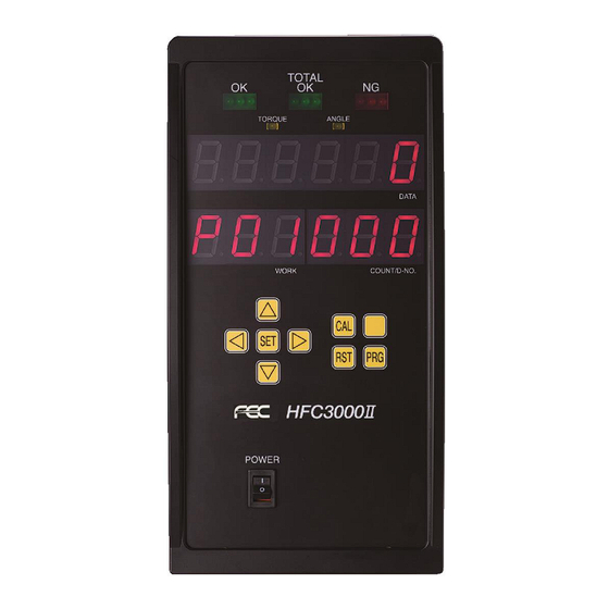
Chapter 3 System Description 3-1 Controller 3-1-1 Controller Front Panel TOTAL OK OK (ACCEPT) NG (REJECT) Lights when acceptable Lights when the Lights when one of the (OK) fastening results fastening results are are obtained for the preset judgment limits is within all preset designated number of not met by the fastening... - Page 31 Chapter 3 Sysytem Description 3-1-2 Controller Bottom Panel *RS232C-2 *Optional DATA REPORT For ID data input ETHERNET MONITOR TOOL Connector for torque and angle Connector for tool cable analog monitor output connection. connection. (PAGE 4-18) Twist lock type connector. Can be connected and disconnected by twisting 90 degrees.
- Page 32 Chapter 3 System Description 3-1-3 Bottom Panel SW1 Switch Settings The SW1 switches on the bottom panel are used to set special functions related to fastening. * Controller Power must be OFF when changing SW1 dip switch settings. Factory Function Setting Details Setting ・...
- Page 33 Chapter 3 Sysytem Description 3-1-4 Bottom Panel SW2 Switch Settings The SW2 DIP switches on the bottom panel are used to change settings related to functions of the controller. * Controller Power must be OFF when changing SW1 dip switch settings.
-
Page 34: Tools
Chapter 3 System Description 3-2 Tools 3-2-1 Angle Tool Right angle hand-held type fastening tool provided with angle head, planetary gear, torque transducer, servomotor, indicator LEDs, and operating switches. Tool cable connector ② Reverse switch High-speed servomotor Torque transducer and ①Start switch planetary gear ③LEDs for judgment and status indications... -
Page 35: Pistol Tool
Chapter 3 Sysytem Description 3-2-2 Pistol Tool Pistol type hand-held type fastening tool provided with planetary gear, torque transducer, servomotor, indicator LEDs, and operating switches etc. High-speed servomotor Torque transducer and planetary gear ②Reverse switch ③LEDs for judgment and status indications ①Start switch Tool cable connector ①Starting switch: Starting switch: When the switch is depressed, the tool (output square drive) - Page 36 Chapter 3 System Description Memo PAGE 3-8...
- Page 37 Chapter 4 Installation and Wiring Chapter 4 Installation & Wiring PAGE 4-1...
-
Page 38: Controller Rear Panel
Chapter 4 Installation and Wiring 4-1 Installation Procedure Follow the installation procedures of the HFC3000 System in the order prescribed below. № Item Contents Page ① Installation Controller mounting and dimensions. PAGE 4-2 Connection of input power Input power connection ②... -
Page 39: Controller Installation Dimensions
Chapter 4 Installation and Wiring 4-2 Controller Installation Dimensions Mounting: 4 points (Rear panel) M6 screws: Use screws with a length equivalent to the installation plate thickness +9mm. Weight: 8.5 kg (18.7lb) <Mounting Precautions> ◆ Do not install the unit at a location that is exposed to vibration. ◆... - Page 40 Chapter 4 Installation and Wiring ●Mounting (Spacing) ・For safe removal of the Controller, install with spacing of 10mm or more (side to side) Caution Upper 100mm or more 10mm 10mm more more 250mm or more 250mm or more Lower PAGE 4-4...
-
Page 41: Input Power Source Connection
Chapter 4 Installation and Wiring 4-3 Input Power Source Connection Connect the dedicated power cable to the connector at a lower portion of the rear panel of the controller. (A power cable is provided as standard.) Primary power connector • Cable supplied for 100-120VAC power (Standard U.S. -
Page 42: Tool Cable Specifications
Chapter 4 Installation and Wiring 4-4 Tool Cable Specifications ■Tool Cable (Cable type: FEB-1309-M**) (For old model tools only (“-01A”, “-02A” suffix)) Total length L Tool Side Controller side ■Tool Cable (Cable type: C15-F7-M**) (For new model tools only (“-10x”, “-20x” suffix)) Total length L Tool Side Controller Side... -
Page 43: External Control Signal Connection
Chapter 4 Installation and Wiring 4-5 External Control Signal Connection Digital Input / Output (DIO) Terminal Block: TB1,2,3 TB3 12 TB3: 12 terminals *The No. 11 terminal at the plug side lacks a alignment pin (See below) TB3 1 TB2 12 TB2: 12 terminals TB1: 12 terminals TB2 1... - Page 44 Chapter 4 Installation and Wiring 4-5-1 Controller I/O Signals Pin No. Signal IN/OUT Description of Function/Usage TB3-1 IN COMMON Common input signal (bipolar) TB3-2,11 +24V Service power +24V output When using this power supply, keep wiring away from 0.5Amax TB3-3,12 supply electrical noise exposure.
- Page 45 Chapter 4 Installation and Wiring 4-5-2 Bank Select Output Signals OUTPUT Definition with BANK SELECT (TB1-12) OFF Pin No. Signal IN/OUT Description of Function/Usage Output when the fastening operation ends with a fastening result TB2-1 REJECT[NG] OUT-1(NO) falling outside a judgment range. Output when the fastening operation ends with the fastening results TB2-2 ACCEPT[OK]...
-
Page 46: Input And Output Circuit Specifications And Recommended Connection Circuit
Chapter 4 Installation and Wiring 4-5-3 Input and Output Circuit Specifications and Recommended Connection Circuit Controller I/O circuit DC power source Input circuit PLC output circuit Input signal Input signal PLC input circuit Output circuit Output signal Output signal *The above diagram shows an NPN type connection example. ・... -
Page 47: Description Of I/O Signals
Chapter 4 Installation and Wiring 4-5-4 Description of I/O Signals +24V、GND: SERVICE POWER SUPPLY PIN No.: TB3-2,3,11,12 User available power supply. (Limited to 0.5amp - in the case external power supply is not available) Do not supply power to the [+24V] and [GND] terminals (24V DC service power supply) on the controller. - Page 48 Chapter 4 Installation and Wiring BATCH OK RESET: BATCH COUNTER RESET SIGNAL PIN No.: TB3-5 After performing fastening for the set number of times (when using the Batch count feature), the cycle count value is cleared automatically at the start of the next fastening process. The count will also be cleared with this signal.
- Page 49 Chapter 4 Installation and Wiring (Continued from previous page) WORK SELECT WORK SELECT WORK SELECT WORK SELECT WORK SELECT WORK SELECT WORK PIN No.:TB3-9 PIN No.: TB1-11 PIN No.: TB1-10 PIN No.: TB1-9 PIN No.: TB1-8 PIN No.: TB1-7 OFF(OPEN) OFF(OPEN) OFF(OPEN) OFF(OPEN)
- Page 50 Chapter 4 Installation and Wiring [Output Signals] When an output signal is “ON,” the voltage at the corresponding output terminal is at the same level as the output common voltage (0V if wired for NPN, 24V if wired for PNP). MANREV / RELAY CONTACT-1 SIGNAL PIN No.: TB2-7 OUT-8...
- Page 51 Chapter 4 Installation and Wiring OUTPUT BANK [OFF] As shown below, the output signal at each terminal takes on one of two definitions in accordance with the combination with the BANK SELECT Input signal being either OFF or ON. BANK SELECT REJECT(NG) WORK SELECT 5 OUT-1...
- Page 52 Chapter 4 Installation and Wiring OUTPUT BANK [ON] CF WARNING PIN No.: TB2-2 OUT-2 ON when the remaining capacity of the CF (compact flash) card is less than 200MB (firmware version 1.310 or later) BATCH SEQUENCE END PIN No.: TB2-3 OUT-3 ON when using the BATCH SEQUENCE function (fastening parameter D-No.
- Page 53 Chapter 4 Installation and Wiring (Continued from previous page) WORK WORK WORK WORK WORK WORK WORK OUTPUT 5 OUTPUT 3 OUTPUT 2 OUTPUT 1 OUTPUT 0 OUTPUT 4 PIN No.:TB2-1 PIN No.: TB2-6 PIN No.:TB3-8 PIN No.:TB3-7 PIN No.:TB2-5 PIN No.:TB2-4 OFF(OPEN) OFF(OPEN) OFF(OPEN)
-
Page 54: Timing Chart
Chapter 4 Installation and Wiring 4-5-5 Input/output signal timing chart ●Basic control signals (Controller firmware ver. 1.304 or later) *1) WORK SELECT requires a response time of 100 msec or more after the READY signal (ON) is output until the START signal is input. *2) After the fastening operation completes, a wait time of 200 msec or more is required to input the next START signal. - Page 55 Chapter 4 Installation and Wiring ●Basic control signals(Controller software version V 1.303 or earlier) ●MANREV Output signal timing chart BANK Output Fastening Fastening Reverse Reverse PAGE 4-19...
-
Page 56: External Monitoring Device Signal
Chapter 4 Installation and Wiring 4-6 External Monitoring Device Signal This auxiliary connector is used to output Torque, Angle, Current & Speed signals to external equipment for monitoring purposes (X-Y Plotter, etc). The signals output from this connector are the same signals that the system receives during the fastening process. - Page 57 Chapter 4 Installation and Wiring 4-6-1 How to Calibrate the External Monitoring Device When pressing the CAL button on the unit display device, the torque voltage is output to the TORQUE OUT pin with the voltage potential difference of approximately ⊿3.7V (from tool ZERO level) At the same time, the torque value detected on the tool is displayed on the DATA display screen.
-
Page 58: Rs-232C Interface Signal
Chapter 4 Installation and Wiring 4-7 RS-232C Interface Signal 4-7-1 RS232C Specifications (RS232C-1) The fastening result data is output in ASCII format from the RS232C output port. (Port is an output ONLY) The default setting of the RS232C ports are indicated below and can be confirmed in the parameter settings [Data No. -
Page 59: Data Format (Rs232C-1)
Chapter 4 Installation and Wiring 4-7-2 Data Format (RS232C-1) The fastening resultant data is output from the RS232C-1 interface at the end of fastening. The data length of the fastening result data in ASCII format is 79 bytes (corresponding to 79 characters) per single fastening operation. - Page 60 Chapter 4 Installation and Wiring When the fastening judgment is NG (REJECT) COUNT No. ACCEPT AXIS No. WORK No. COUNT 39H 39H PEAK TORQUE JDG OCR FINAL ANGLE JDG OCR 20H 31H SIGN SIGN FINAL TORQUE JDG OCR RATE1 JDG OCR 20H 31H 30H 2EH SIGN...
-
Page 61: Ethernet Interface
Chapter 4 Installation and Wiring 4-8 Ethernet Interface The Ethernet interface is the TCP/IP Ethernet port dedicated to communication with the HFC3000 ® User Console installed in a PC with Windows A commercially available Ethernet cable (crossover/straight) can be used. (CAT5 or higher) The TCP/IP factory settings of the controller are shown below. -
Page 62: Tcp/Ip Setup Procedure
Chapter 4 Installation and Wiring 4-8-1 TCP/IP SETUP PROCEDURE (Windows ®) The Ethernet settings on the PC side may need to be changed in order to communicate to the controller via Ethernet. The “default” TCP/IP settings of the controller are set at the factory, however, it’s possible they may have been user configured. - Page 63 Chapter 4 Installation and Wiring 4. Select “Properties” in Local Area Connection Status. 5. In Local Area Connection Properties, select “Internet Protocol Version 4 (TCP/IPv4)” and then select “Properties”. PAGE 4-27...
- Page 64 Chapter 4 Installation and Wiring 6. In Internet Protocol Version 4 (TCP/IPv4) Properties, select “Use the following IP address” and change the IP address, the subnet mask, and the default gateway. Match the values of the 3 upper positions to the IP address set values of the Unit.
- Page 65 Chapter 4 Installation and Wiring 4-8-1 TCP/IP SETUP PROCEDURE (User Console Software) 1. If the TCP/IP settings of the controller are set to anything other than the default settings, then the new IP address will need to be registered in the HFC3000 User Console Software. The communication setting window is displayed automatically when the User Console software is started.
- Page 66 Chapter 4 Installation and Wiring 4-A. If connection with the Unit is successful, the “Connect” indication changes from “Disconnect” to “[****]=[Connect]” (where **** is the IP address set in procedure 2.) is displayed at the lower left status bar of the User Console. After connection succeeds, reading and writing of respective set values, monitoring of fastening result indications, etc.
- Page 67 Chapter 5 Power Up and Operational Tests Chapter 5 Power Up and Operational Tests PAGE 5-1...
-
Page 68: Items To Be Checked Before Power On
Chapter 5 Power Up and Operational tests 5-1 Items to be Checked Before Power On (1) Check connection between tool and Controller Connect the cable between the tool and the controller securely. Confirm the cable has no stress points when moving the tool. If the cable has any stress applied while moving, fix cable management to reduce cable stress before powering up (2) Check wiring for I/O signals Connection with the external control equipment must be made at the terminal block on the rear panel... -
Page 69: Items To Be Checked When Powering On The Equipment
Chapter 5 Power Up and Operational Tests 5-2 Items to be Checked When Powering On the Equipment Confirm that the display changes as follows when the control power is turned on. RUN Mode Power activation All segments are lit for approx. -
Page 70: Input Initial Setting Data
System. The system will not run until this data is correctly set-up. Programming should be performed using the FEC Inc. “HFC3000 Userconsole” software to simplify the programming operation and to provide a means of creating a back-up file of the set-up. - Page 71 Chapter 6 Fastening Operation Chapter 6 Fastening Operation PAGE 6-1...
-
Page 72: Changing Between Run And Program Modes
Chapter 6 Fastening Operation 6-1 Changing between RUN and PROGRAM Modes There are two modes of the handheld tool - the RUN (operation) and PROGRAM (setting) modes. In the RUN (operation) mode, the fastening operation and the fastening result judgment are indicated. Parameters can be changed in the PROGRAM (setting) mode. - Page 73 Chapter 6 Fastening Operation (1) Controller Operation / Check Buttons ①CAL Button: CAL voltage check When this button is pressed, a full scale calibration check of the tool torque transducer tool is performed. The calibration torque value is indicated in the “DATA” section of the display. If as a result of the check, the value is within the specified ranges, the status LED on the tool flashes alternately in green <-->...
- Page 74 Chapter 6 Fastening Operation (4) Tool Operation A pistol type hand-held fastening tool is shown below for reference. Right Angle and Straight (inline) are similar as far as operation switches and indicators (but may have slight differences) Torque transducer High-speed servomotor and planetary gear ③LEDs for judgment and status indications...
-
Page 75: Run Mode
Chapter 6 Fastening Operation 6-2 RUN Mode When the power is activated (turned ON) and the initialization process ends, the (RUN mode) is entered. In the RUN mode, mainly the fastening results, abnormal status, Axis No., parameters, etc., are indicated. Data Display Section (RUN Mode) DATA Display COUNT/D-No. -
Page 76: Changing Display Modes (In The Run Mode)
Chapter 6 Fastening Operation 6-2-1 Changing Display Modes (in the RUN Mode) Five modes can be selected while in the RUN state by pressing the [◄] or [►] push-button. By using “Status Display Mode” is the [▲] or [▼ ] push-button, the display content can be changed. automatically selected when the fastening starts and “Fastening Result Mode”... -
Page 77: Real Time Display Mode
Chapter 6 Fastening Operation 6-2-2 Real Time Display Mode In the real time display mode, “Non.” (Monitor) is indicated on the WORK Display. By pressing the [▲] or [▼] push-button, the “D-NO” can be changed ±1. The numbers can be advanced 5 at a time by holding the [▲] or [▼] push-button longer. “WORK” “COUNT/D-NO”... - Page 78 Chapter 6 Fastening Operation ● List of Contents Displayed in the Real Time Mode COUNT/ WORK DATA Unit D-NO 【Torque value display】 The torque value from the torque transducer is displayed in real time. The torque voltage that is converted to the full scale torque is output by pressing [CAL] pushbutton.
- Page 79 Chapter 6 Fastening Operation [Tool Response•St1.] (0~255) Factory Adjustment only [Tool Response•St2.] (0~15) Factory Adjustment only [Tool Response•Ad1.] (0~255) The actual sensing level of the starting trigger switch is indicated. [Tool Response•Ad2.] (0~255) The actual sensing level of the F/R slide switch is indicated. [Tool Response•G.
-
Page 80: Fastening Result Display Mode
Chapter 6 Fastening Operation 6-2-3 Fastening Result Display Mode The following data is displayed in Fastening Result Mode. In the fastening result mode, “r.” is indicated at the 100s digit of the PAR No. indication part and the parameter No. (01 to 64) of the fastening operation that was performed is indicated by the 10s and 1s digits. - Page 81 Chapter 6 Fastening Operation ● List of Contents Indicated in the Fastening Result Mode (Reject display rotates (auto) for gray items only) COUNT Unit WORK DATA /D-NO Peak Torque H/L Final Angle Rate 1 H/L Nm/deg Rate 2 H/L Nm/deg Rate 3 H/L Nm/deg Time H/L...
-
Page 82: Parameter Setting Mode
Chapter 6 Fastening Operation 6-2-4 Parameter Setting Mode The following data is displayed in Fastening Parameter Display Mode. In the parameter setting mode, “P.” is indicated at the leftmost digit of the PAR No. display and the parameter No. (01 to 32) is indicated by the 10s and 1s digits. -
Page 83: System Parameter Display Mode
Chapter 6 Fastening Operation 6-2-5 System Parameter Display Mode The following data is displayed in System Parameter Display Mode. “SYS” is indicated in the PAR No. display area. By pressing the [▲] or [▼] push-button, the “D-NO” can be changed ±1. The numbers can be advanced 10 at a time by holding the [▲] or [▼] push-button longer. -
Page 84: Status Display Mode
Chapter 6 Fastening Operation 6-2-6 Status Display Mode In the Staus Display Mode (run mode), the currently selected work (parameter) No. (01 ~ 64) is indicated in the WORK Display. The Spindle No. of the controller is indicated by the 10s and 1s digits of the COUNT/D-No. - Page 85 Chapter 6 Fastening Operation During fastening operation, the operation speed and the fastening step are indicated in the WORK display, as well as the parameter No. (01~ 64) that is currently in operation. The mode cannot be changed in the display during fastening operation. Transition to the fastening result mode is performed automatically after the fastening ends.
-
Page 86: Parameter Program Mode
Chapter 6 Fastening Operation 6-3 Parameter Program Mode NOTE: Setting up parameters is performed easier using the HFC3000 Software – this method is provided in the case software is not available The parameter settings can only be changed/programmed when in the BYPASS / PROGRAM mode. The Data No. -
Page 87: Parameter Selection Mode
Chapter 6 Fastening Operation 6-3-2 Parameter Selection Mode Immediately after “Parameter Selection Mode” is established, the cursor (blinking number) is displayed on the PAR No. Display when the [◄] push-button is pressed. When the [►] push-button is pressed, the cursor (blinking number) is displayed on the D-No. Display. The display set value of the cursor (blinking character) can be changed by ±1 using the [▲] or [▼] push-button. - Page 88 Chapter 6 Fastening Operation In the Parameter selection mode, “SYS.” is displayed in the WORK Display in the case of a SYSTEM parameter and the parameter No. (P.01 to P.64) is indicated in the case of a FASTENING parameter. The WORK Display is changed by pressing the [►] or [◄] button and the content of the data No. is indicated in the upper display section accordingly.
-
Page 89: Parameter Editing Mode
Chapter 6 Fastening Operation 6-3-3 Parameter Editing Mode Immediately after changing to the “Parameter Editing Mode,” the cursor (flashing number) is displayed in the upper section of the display. When the [▲] or [▼] button is pressed, the numerical value at the cursor position changes by ±1. When the [◄] or [►] button is pressed, the digit in the cursor position changes by ±1. - Page 90 Chapter 6 Fastening Operation ● System Parameter Setting Method Parameter displayed with [SYS] in the PAR No. display is a System Parameter. Press the [SET] push-button after editing the parameter. Once the SET push-button has been pressed the [DATA] display will show “CHAnGE”and “no” will appear on the “D-NO” display. “yES”...
-
Page 91: Parameter Copy/Erasing The Fastening Result History/Formatting Of The Cf Card
Chapter 6 Fastening Operation 6-4 Parameter Copy / Erasing the Fastening Result History / Formatting of the CF Card NOTE: Copying parameters is performed easier using the HFC3000 Software – this is provided in the case software is not available When multiple parameter sets need to be changed, one parameter can be copied to another parameter while in the parameter edit mode. - Page 92 Chapter 6 Fastening Operation ● Erasing Fastening Data History All of the fastening data results history saved in the controller can be erased with similar procedures. ・Once the fastening results history is erased, the data cannot be retrieved. Be careful when erasing the data. ●...
-
Page 93: Fastening Reject (Ng) Result Indications
Chapter 6 Fastening Operation 6-5 Fastening Reject (NG) Result Indications When a fastening reject (NG) occurs, in addition to the NG lamp indication, the item that rejects during the fastening is indicated in the numerical value portion of the display. In the case of fastening to standard torque, judgments are made in the order: rate high/low limits, differential angle high/low limits, fastening time high/low limits, angle high/low limits, peak torque high/low limits, and final torque high/low limits, and the item with which the 1... -
Page 94: Example Of Fastening Reject Item Display
Chapter 6 Fastening Operation 6-5-1 Example of Fastening Reject item Display 1. Torque High Limit Judgment Peak Torque High limit Reject Cause: Seizing / locking of threads, excessive speed Torque Inhibit High limit Reject Cause: Workpiece problem, Torque required during thread cutting is too high 2. - Page 95 Chapter 6 Fastening Operation 4. Fastening Time High Limit Judgment 1ST Time High limit Reject Cause: Non-engagement / broken socket, no fastener present 2ND Time High limit Reject Cause: Fastener is yielding, fastener is cutting threads, socket disengaged 5. Rundown Revolutions High Limit Judgment Rundown Revolutions High Limit Reject Cause: Bolt length wrong, socket disengaged 6.
-
Page 96: Reject Judgment / Limits
Chapter 6 Fastening Operation 6-5-2. Reject Judgment / Limits Judgments by the high and low limit values of torque, angle, time, and rundown revolutions are performed during the fastening operation or after the end of fastening. The REJECT judgment is made if a fastening result falls outside the high or low limit range. - Page 97 Chapter 6 Fastening Operation The following judgments cannot be disabled. ・Peak Torque ・Final Angle ・Time Caution ●Torque Check [N•m] •Peak Torque The high and low Peak Torque limit values during fastening on are set. Fastening operation is ended if the peak torque high limit value is exceeded during fastening operation.
- Page 98 Chapter 6 Fastening Operation ●Angle Check [deg] •Final Angle The Angle high and low limit values from the point of Snug Torque to the end of fastening are set. Fastening operation is ended if the angle high limit value is exceeded during the fastening operation. ●Timeout Check [sec] •1st Time The 1...
- Page 99 Chapter 6 Fastening Operation ●Rate Check Three torque rate areas capable of judging the rise of torque vs. angle (slope) can be used to monitor the fastening operation. A rate start torque (angle) and a rate end torque (angle) set the boundaries of each area and the torque slope (slope of the torque vs.
- Page 100 Chapter 6 Fastening Operation •If the rate start torque (angle) cannot be detected during fastening operation, the rate judgment will not be performed. •Under the following conditions, the torque (angle) at the end of fastening is judged as the rate end torque (angle).
- Page 101 Chapter 6 Fastening Operation Differential Angle Check ● After the end of fastening, the differential angle, which is the difference between the seating point (angle) of the final torque and the seating point (angle) calculated from rate 2, is measured and judged. The seating point (angle) calculated from rate 2 is based on the rate 2 start torque (angle) and the rate 2 end torque (angle).
- Page 102 Chapter 6 Fastening Operation ● Break away Torque Check The Break away Torque value during reverse rotation is judged . When D-No. 110 [Reverse Torque High Limit] is exceeded, the fastening operation is ended and an abnormal is output. (A09-08 “Reverse Torque Error”) The detection high limit depends on the firmware version installed;...
- Page 103 Chapter 6 Fastening Operation ● Current Value Warnings Motor current draw during fastening is monitotred and can be used to monitor the motor current draw over time (for PM evaluation). After the end of the fastening operation, the peak current value is judged to be within the high and low limit ranges.
-
Page 104: Fastening Speed And Time
Chapter 6 Fastening Operation 6-5-3 Fastening Speed and Time The HFC3000 System is user-programmable for operations involving multiple speed settings. The use of multiple speeds during the fastening process aids in socket engagement, achieving cycle time and control ling the applied torque during all stages. Speed functions work the same for Torque Control and Angle C ontrol using any of the previously stated standard Judge functions. - Page 105 Chapter 6 Fastening Operation 2. Upon reaching 1ST Torque/Angle, 1 Time ends and 2 Time begins. 1ST Torque/Angle is the shift point from 1 Speed to 2 Speed. 3. For a 2 step fastening, the system will fasten to Standard Torque/Angle using 2 Speed during the specified 2 Time limits.
-
Page 106: Auxiliary Attachments - Tubenut Head Setup
Chapter 6 Fastening Operation 6-5-4 Auxiliary Attachments - Tubenut Head Setup Tubenut heads are used for applications that require a socket to be inserted around a tube to fasten an accompanying tubenut. They require a special function to re-align the “U” shaped socket back to its “open”... - Page 107 Chapter 6 Fastening Operation Recommended Parameter Set-up for Tubenut Head The following parameters are recommended for setting up the Tubenut head function. Gear Head Option Setup [SYS], [D-No]-036 (Default Setting “0”) **(Can only be set using the front display keypad) Change for use with Tubenut head (Set as below) 0: Standard Head...
- Page 108 Chapter 6 Fastening Operation Tubenut Head Operation When using a Tubenut head, a special function is required to re-align the socket after normal fastening operations and allow the socket to be placed onto the nut to be fastened. The start trigger must be held “ON”...
-
Page 109: Parameter Structure
Chapter 6 Fastening Operation 6-6 Parameter Structure Parameter No.: SYS System Parameters 000: Torque Unit 001: Software Version 002: Amplifier Version 003: System Indication 504:Touch Panel Number of Retries Parameter No. P. 64 Parameter No. P. 63 Parameter No. P. 62 Parameter No. -
Page 110: System Parameters
Chapter 6 Fastening Operation 6-6-1 System Parameters <System Parameters> Par No. Indication: SYS [Setting Change marked “O” user changable] Setting Item D-No. Contents Unit change ○ Torque Unit Software Version Amplifier Version System Indication ○ Spindle Adapter Gear Ratio For Adjustment by the Manufacturer For Adjustment by the Manufacturer Communication Axis Indication Axis Cycle Count (×1 million) - Page 111 Chapter 6 Fastening Operation Setting Item D-No. Contents Unit change Connected Tool No. Connected Tool Information “015-P1” Connected Tool CAL Torque Decimal Point Position Connected Tool CAL Torque Connected Tool CAL Voltage Connected Tool ZERO Voltage Connected Tool Internal Gear Ratio (×100) Connected Connected Tool Serial No.
- Page 112 Chapter 6 Fastening Operation Setting Item D-No. Contents Unit change CF Card Storage Capacity RS232C-2 Communication Speed RS232C-2 Parity RS232C-2 Stop Bit RS232C-2 Word Length Not used Not used Option Information2 Not used Not used ID Input Selection Add STX, ETX External Input Select Reference Data Start Reference Data End...
- Page 113 Chapter 6 Fastening Operation System Parameters (controller Information 1) D-No.000 Torque Unit All fastening parameters within the Controller will have the same torque unit. Set Value Unit N・m kgcm Ftlbs Inlbs D-No. 001 Software Version Cannot be changed. This is the software version of the controller. D-No.
- Page 114 Chapter 6 Fastening Operation D-No.010 controller Maximum Current Cannot be changed This indicates the maximum current value of the controller. D-No. 011 IP Address (upper 6 digits) D-No. 012 IP Address (lower 6 digits) Setting range: 0 to 255 The IP address for the controller Ethernet port is set here. In a MULTI system, the Ethernet port for the MASTER spindle is only used.
- Page 115 Chapter 6 Fastening Operation D-No.026 controller SW1 Setting State D-No.027 controller SW2 Setting State The setting states of the DIP switches of the controller (SW1 and SW2 on the controller bottom panel) are indicated in the two upper right LED segments (“00H” means 00 hex) D-No.026 D-No.027 The ON/OFF states of SW No.
- Page 116 Chapter 6 Fastening Operation System Parameters (Options) SYS.030 Parameter Change Unlock Code Standard setting: 000000 Allows the setting of a numerical password to restrict Parameter setting from the front display panel. When a value other than the standard setting (“000000”) is set, changing the controller to the PROGRAM mode displays the password (numerical value) input screen.
- Page 117 Chapter 6 Fastening Operation D-No.035 System Option 3 Standard setting: 000000 Option 3 function setting xxxxx1: Restrict cycle start after Total Accept (0: OFF ./ 1: ON). ・Set to “1” to prohibit a restart after a TOTAL-OK In order to restart the fastening operation, turn ON any of the following input signals. RESET STOP PROGRAM...
- Page 118 Chapter 6 Fastening Operation System Parameters - Connected Tool Settings D-No.100 Connected Tool No. Assigned Tool No. corresponding to the connected tool model. Please refer to “Tool Models.” D-No.101 Connected Tool Information The maximum torque and motor capacity of D-No. 100 “Connected Tool No.” D-No.102 Tool CAL Torque Decimal Point The decimal point position of the torque value of D-No.
- Page 119 Chapter 6 Fastening Operation System Parameters – Controller Information D-No.200 Controller Setup Tool No. Setting range: Tool No. registered for the model The Tool No. of the connected tool is settable (with reference to “Tool Models”). When the controller setup tool no. is changed, initialization and automatic correction of the fastening parameter set values is performed (for the new tool size connected) D-No.201 Controller Setup Tool Information The maximum torque and motor capacity of the tool of D-No.
- Page 120 Chapter 6 Fastening Operation System Parameters – Fieldbus I/O Interface Information D-No.300 Connected Fieldbus Information The type of fieldbus installed on the Expansion 1 is indicated. No Expansion Unit 1 installed (Standard IO) MFC-CC Installed (CC-Link) MFC-PB Installed MFC-DN (PROFIBUS Installed DP-V1) (DeviceNet)
- Page 121 Chapter 6 Fastening Operation (“o” indicates which fieldbus uses which SYS D-No) PROFIBUS PROFINET CC-Link DeviceNet EtherNet/IP SYS.300 DP-V1 ○ ○ ○ SYS.303 ○ ○ SYS.304 ○ SYS.305 ○ SYS.306 ○ ○ ○ ○ ○ SYS.307 ○ ○ ○ ○ ○...
- Page 122 Chapter 6 Fastening Operation D-No.309 Message Block Byte Length [byte] (Fieldbus only) The programmed message block byte length of the fieldbus set in the controller is indicated. Fieldbus type CC-Link DeviceNet PROFIBUSDP-V1 PROFINET IO EtherNet/IP 144byte 250 byte 64 byte 250 byte 250 byte D-No.310 Message Setting Byte Length “PLC →...
- Page 123 Chapter 6 Fastening Operation System Parameters – CF / RS232 Input Information D-No.400 CF Card Storage Capacity [%] The storable capacity of the CF card is displayed. D-No.401 RS232C-2 Communication Speed [bps] The communication speed of the RS232C-2 interface is displayed. D-No.402 RS232C-2 Parity The parity of the RS232C-2 interface is displayed.
- Page 124 Chapter 6 Fastening Operation System Parameters – Remote Touch panel Information D-No. 500 IP Address (upper 6 digits) D-No. 501 IP Address (lower 6 digits) Setting range: 0 ~ 255 The IP address of the remote touch panel connected to the controller is displayed. D-No.502 Touch Panel Function / Language Setup Standard setting:0 Setting range: 0~4 Allows disable / enable of the remote touch panel function and the language setting...
- Page 125 Chapter 6 Fastening Operation 6-6-2 Fastening Parameters Items in gray cells are not displayed) Torque Angle Item PAR No. D-No. Contents Method Method Fastening Method ○ ○ Fastening Steps ○ ○ Fastening Option Fastening P.01~ ○ ○ Judgment Item 1 Settings P.64 ○...
- Page 126 Chapter 6 Fastening Operation Torque Angle Item PAR No. D-No. Contents Method Method ○ ○ Rate 1 Low Limit ○ ○ Rate 1 High Limit ○ ○ Rate 2 Low Limit ○ ○ Rate 2 High Limit ○ ○ Rate 3 Low Limit ○...
- Page 127 Chapter 6 Fastening Operation Torque Angle Item PAR No. D-No. Contents Method Method ○ ○ Number of Accept [times] P.01~P.64 Others ○ ○ Angle Head Torque Variation Rate[%] ○ ○ CW Servo Lock Time Between Steps ○ ○ CW Wait Time Between Steps ○...
- Page 128 Chapter 6 Fastening Operation Fastening Settings D-No.000 Fastening Method Standard setting: 0 Sets the Fastening Method. 0: Torque Method, 1: Angle Method D-No. 001 Fastening Steps Standard setting: 1 The number of steps used in fastening 1: 1-Step Fastening ・ Fastening is performed using D-No. 103 [Standard Torque] or D-No. 202 [Standard Angle] as a target stopping point (with no stops in between) 2: 2-Step Fastening ・...
- Page 129 Chapter 6 Fastening Operation The fastening judgment is not performed regardless of the values of the high and low limit set values when the settings of fastening parameters D-No. 003 Caution “Judgment Item 1” and D-No. 004 “Judgment Item 2” are set to “0” (off). D-No.
- Page 130 Chapter 6 Fastening Operation D-No. 004 Judgment Item 2 Default setting: 000001 *****1: Timeout Check Cannot be Disabled. ・ Judges whether the fastening has taken place within the set high/low time limits. 1 Time is from the start of fastening to D-No. 105 [1st Torque] or D-No. 205 [1st Angle]. 2nd Time is from D-No. 105 [1st Torque] or D-No.
- Page 131 Chapter 6 Fastening Operation D-No.005 After Fastening Operation Default setting: 000000 *****1: 1 Pulse Reverse ・ After the end of fastening, the torque is reversed up to the D-No. 121 [1 Pulse Reverse Torque High Limit]. The 1 Pulse Reverse is performed at the D-No. 410 [1 Pulse Reverse Speed] for the D-No.
- Page 132 Chapter 6 Fastening Operation D-No.006 Interrupt Operation During Fastening Default setting: 000000 *****1: Pulse Fastening Operation ・Set to “1” to enable pulse fastening function (pulsing is started after detection of 1 Torque). ****1*: Gyro Setup Enable ・With a Pistol (P type or T type too)l, the Gyro operation functions are enabled when this is set to “1” (ON).
- Page 133 Chapter 6 Fastening Operation Torque D-No. 100 Calibration Torque [N・m] Setting range: 70% ~ 120% of the standard calibration torque of the tool This sets the calibration torque value of the connected tool. In the case where the tool calibration needs to be adjusted (due to outside influences such as a sockets, extensions, external offset gear or workpiece characteristics, the indicated fastening result value differs from the result obtained by a certified fastening torque tester, etc., the fastening torque can be corrected by this setting.
- Page 134 Chapter 6 Fastening Operation D-No. 104 Ramp Down Start Torque [N・m] Setting range: 0 ~ D-No. 100 [Calibration Torque] × 1.0 The torque value at which D-No. 401 [Freerun Speed] is switched to D-No. 402 [1st Speed] is set. However, even if the ramp down start torque is not detected, switching to D-No. 402 [1st Speed] is performed when D-No.
- Page 135 Chapter 6 Fastening Operation D-No. 110 Reverse Torque High Limit [N・m] Setting range: 0 ~ D-No. 100 [Calibration Torque] × 1.3 Sets the reverse high limit value for torque during reverse operations. When the reverse torque high limit is exceeded during a reverse operation, the fastening is stopped and abnormal A.09-08 “Reverse Torque Error”...
- Page 136 Chapter 6 Fastening Operation D-No. 118 Final Torque Low Limit [N・m] Setting range: 0 ~ D-No. 100 [Calibration Torque] × 1.1 D-No. 119 Final Torque High Limit [N・m] Setting range: 0 ~ D-No. 100 [Calibration Torque] × 1.3 Sets the low and high limit values of the torque at the end of fastening. ・...
- Page 137 Chapter 6 Fastening Operation Angle D-No. 200 Final Angle Low Limit [deg] D-No. 201 Final Angle High Limit [deg] Setting range: 0 ~ 9999.9 Sets the low and high limit values of the output judgment angle. When the fastening angle exceeds the final angle high limit or falls below the final angle low limit, a REJECT judgment is made.
- Page 138 Chapter 6 Fastening Operation Rate D-No. 300 Rate 1 Low Limit [N・m/deg] Setting range: - maximum torque rate of tool ~ maximum torque rate of tool Sets the low limit value of Rate 1 (slope of torque vs. angle) between the two points of D-No. 112 [Rate 1 Start Torque] ~ D-No.
- Page 139 Chapter 6 Fastening Operation Time D-No. 310 Initial Time [sec] Setting range: 0.0 ~ 999.9 Setting of Initial time can be used as a slower rpm to aid in socket / fastener engagement, reduce initial engagement shock, etc., at the start of fastening. Operation at D-No. 400 [Initial Speed] is executed during the initial time or during D-No.
- Page 140 Chapter 6 Fastening Operation Speed ・ The minimum and maximum tool rotation speed differs according to the tool model. Please refer to “Tool Models” regarding the allowed input range. Caution D-No. 400 Initial Speed [rpm] Setting range: Minimum tool speed to maximum tool speed Setting of Initial speed can be used as a slower rpm to aid in socket / fastener engagement, reduce initial engagement shock, etc., at the start of fastening.
- Page 141 Chapter 6 Fastening Operation D-No.405 Reverse 1 Speed [rpm] Setting range: Minimum tool speed to maximum tool speed Sets the speed during reverse operation. The speed at which reverse rotation is performed while the REV. pushbutton on the controller is pushed, When the Reverse-FWD tool switch is rotated to the reverse position or the Reverse I/O signal is turned on.
- Page 142 Chapter 6 Fastening Operation Revolutions/Current D-No. 500 Freerun Revolutions [rev.] Setting range: 0 ~ 99.9 Sets the number of revolutions before D-No.401 [Freerun Speed] is switched to D-No.402 [1 Speed]. Even if the Freerun Speed Revolution is not reached, it switches to D-No.402 [1 Speed] when the D-No.104 [Ramp Down Start Torque] is detected.
- Page 143 Chapter 6 Fastening Operation Other / Time D-No.540 Number of Accept [#] Setting range: 0~99 When using the “Batch’ function, the number of Accept fastenings to designate a ‘Batch OK’. (Example: if set to ‘4’, you would need four consecutive Acceptable fastenings to output a ‘Batch OK’ signal and light the TOTAL OK on the front of the controller) D-No.541 Angle Head Torque Variation Rate [%] Default value: 0, Setting range: 0~100...
- Page 144 Chapter 6 Fastening Operation D-No.546 Reverse Ramp Up Time [msec] Setting range: 100~5000, Default setting: 500 Sets the time constant for acceleration from zero speed to the maximum reverse rotation speed. The reverse ramp up time is used in the following cases; ・Manual reverse by turning on (“OFF”→”ON”) the PLC I/O input signal “REVERSE.”...
-
Page 145: Pulse Operation
Chapter 6 Fastening Operation 6-6-3 PULSE OPERATION Recovery Pulse Operation D-No.005 After Fastening Operation: Recovery Pulse ON Set value: xxxx1x D-No.550 Recovery Pulsing Count [times] Setting range: 0~50 D-No.551 Recovery Pulsing Speed [rpm] Setting range: within tool speed range Setting “1” for [Data No. 005 After Fastening Operation] turns ON Recovery Pulse Operation which will perform refastening for the number of times defined by the recovery pulsing count (D-No. - Page 146 Chapter 6 Fastening Operation Pulse Fastening Operation D-No.006 Interrupt Operation During Fastening : Pulse Fastening Operation ON Set value: xxxxx1 Setting “1” for [Data No. 006 Fastening Interrupt Operation] the Pulse Fastening Operation is turned ON and the pulse fastening operation is performed from the detection of the 1st torque (D-No. 105) to the detection of the standard torque (D-No.
-
Page 147: Gyro Operation
Chapter 6 Fastening Operation 6-6-4 GYRO OPERATION D-No.006 Interrupt Operation During Fastening : Gyro Setup Enable ON Set value: xxxx1x Setting “1” for [Data No. 006 Interrupt Operation During Fastening] turns ON the Gyro Settings, which monitors the handle swing during fastening to protect the operator from ergonomic hand ‘twisting’ fatigue. -
Page 148: Sequence Operation
Chapter 6 Fastening Operation 6-6-5 SEQUENCE OPERATION Besides the standard fastening process provided in Parameter 1 ~ 64, two types of sequence operation modes are provided which, are available for accommodating applications requiring more complex processes. 64 fastening parameters can be used to program up to 8 stages in a fastening sequence. Batch sequence: Multiple parameter settings are used and at each stage, an operation each requiring a separate start signal, is repeated for the number of times designated by a “Count.”... - Page 149 Chapter 6 Fastening Operation [1: Batch Sequence] The parameter No. and count are set for the operation at each stage (the Dwell time is not used). Example: If the setting is [02. 05. □□], after the fastening operation using parameter 2 is completed 5 times, the next stage is entered (a fastening operation is counted only when the ACCEPT judgment is made).
- Page 150 Chapter 6 Fastening Operation <Program Examples2> Continuous Sequence (Automatic Sequence Function): Six digits of data, which designate the parameter No. and the dwell time (dwell after fastening) before entering the next stage, are used in each stage. 0 1 . 0 0 . 0 5 The dwell time (in msec) is executed after completion of fastening.
- Page 151 Chapter 7 Troubleshooting Chapter 7 Troubleshooting PAGE 7-1...
-
Page 152: Abnormal State Display
Chapter 7 Troubleshooting 7-1 Abnormal State Display When an abnormal condition is detected by the system, the affected spindle stops and indicates an abnormal code. For ease of troubleshooting the cause of the abnormal, the system provides an abnormal code in the [PAR NO] display and an abnormal sub-code in the [D-NO] display. - Page 153 Chapter 7 Troubleshooting 7-2 Abnormal Details / Causes & Recovery Methods Torque Transducer Errors [A.01 - *] • Code A01-01 – TORQUE TRANSDUCER / ZERO MASTER ERROR The System detected a Zero Level Check error during power on initialization. CAUSE: •...
- Page 154 Chapter 7 Troubleshooting • Code A01-03 - TORQUE TRANSDUCER / ZERO CHECK ERROR The System detected a Zero Voltage Level Check error after a fastening START was attempted. CAUSE: • When the tool torque transducer is sensing excessive torque due to pressure on the tool body during a START signal to the controller (when tool normally should be in an idle state with no external forces applied) •...
- Page 155 Chapter 7 Troubleshooting • Code A01-05 – TORQUE TRANSDUCER / CAL JUDGMENT ERROR The System detected a Calibration Voltage error after a fastening START was attempted with the Calibration Check function disabled. CAUSE: • When the tool torque transducer is sensing excessive torque due to pressure on the tool body during a START signal to the controller (when tool normally should be in an idle state with no external forces applied) •...
- Page 156 4. Replace the defective component. 5. If TOOL ID data is missing or corrupt, replace tool and return to FEC to be re-programmed (to see TOOL ID Data, use HFC3000 software to upload TOOL ID data and view contents “Details”...
- Page 157 Chapter 7 Troubleshooting • Code A03-05 - PREAMPLIFIER / WATCHDOG TIMER ERROR Communications error between the tool preamplifier (torque transducer) and the controller. CAUSE: 1. The tool cable is not connected or has lost connection during communication. 2. When the torque transducer, transducer cable or the controller malfunctions. RECOVERY: 1.
- Page 158 Chapter 7 Troubleshooting • Code A04-04 - SYSTEM MEMORY ERROR / STORED DATA WRITE ERROR An error occurred during a WRITE attempt to SDRAM saved data. CAUSE: 1. If the controller is located in an electric or magnetic noise field. 2.
- Page 159 Chapter 7 Troubleshooting Servo Amplifier Reply Errors [A.05 - *] • Code A05-01 - SERVO AMPLIFIER REPLY ERROR / NO REPLY FROM RESOLVER The controller is attempting to turn the motor but is not receiving any signals back from the resolver to indicate that the tool is actually turning or the speed reference on the amplifier is not responding.
- Page 160 Chapter 7 Troubleshooting Servo Amplifier Type Errors [A.06 - *] • Code A06-01 - SERVO TYPE ERROR / SERVO TYPE MISMATCH The connected tool type (Shown in System (SYS) Parameter D-No. 100) does not match the tool type programmed into the controller (Shown in Parameter D-No. 200). This error may occur when controllers or tools are replaced with the wrong type unit or the parameter program does not match the tool size installed.
- Page 161 Chapter 7 Troubleshooting • Code A08-04 - SERVO AMPLIFIER ERROR / OVER CURRENT The HFC controller servo circuit experienced a current overload. CAUSE: 1. The fastener rundown speed may be set too high and creating high current spikes when it tries to ramp down to a slower speed or as the fastener is seated to the work piece.
- Page 162 5. Check the cable connections. 6. If the problem remains, a larger tool assembly may be required for this application. Please contact FEC. • Code A08-11 - SERVO AMPLIFIER ERROR / RESOLVER SIGNAL ERROR The resolver signal received from the tool in the controller is not correct.
- Page 163 Chapter 7 Troubleshooting • Code A08-16 - SERVO AMPLIFIER ERROR / MOTOR DRIVE POWER VOLTAGE ERROR The AC input power to the HFC Unit is disconnected or was turned off during fastening. CAUSE: 1. The controller internal power supply has failed. 2.
- Page 164 Chapter 7 Troubleshooting Parameter Errors [A.09 - *] • Code A09-02- PARAMETER ERROR / MISSING PARAMETER SETUP Some parameter settings are missing, set to “0” or out of the specified range of the tool. RECOVERY: 1. Check that the parameter presets are not set as <0> or out of the specified range of the tool. Confirm and set the affected value(s) in the acceptable range 100: Calibration Torque 102: Peak Torque High Limit...
-
Page 165: Spindle Judgment: Checking Reject Reason
Chapter 7 Troubleshooting 7-3. Spindle Judgment: Checking REJECT Reason When a value falling outside the high and low limit range (Lower than the low limit or higher than the high limit value) of a fastening parameter is detected during a fastening operation, the REJECT judgment is made and the NG LED of the controller lights up red. -
Page 166: Ethernet Communication
Chapter 7 Troubleshooting 7-4. Ethernet Communication If Ethernet communication of the HFC Software cannot be performed with the PC being used, please refer to the following troubleshooting table. Item Countermeasures/Check Details PAGE Is there an error in the TCP/IP Section Check the TCP/IP setup procedures. - Page 167 Chapter 7 Troubleshooting ●Method for Confirming Using Command Prompt Functions (Windows 7) 1. Connect the controller and the PC with the PC communication cable. 2. In the Windows Start menu, click “All Programs” → “Accessories” → “Command Prompt.” (Or search “Command Prompt” using search function) 3.
-
Page 168: Rtc (Real Time Clock Setup)
Chapter 7 Troubleshooting 7-5. RTC (Real Time Clock setup) The HFC3000 controller is equipped with a RTC (real time clock) for holding date and time data. ・Model ANG-RTC ・Backup power source Before June 2016: Backup by electric double layer capacitor July 2016 and after: Lithium Battery Backup duration in power OFF state Approx. - Page 169 Chapter 8 Options Chapter 8 Options PAGE 8-1...
-
Page 170: Compactflash (Cf) Card
Chapter 8 Options 8-1 Compact Flash (CF) Card 8-1-1 Summary Fastening results and fastening curves can be stored as files in a Compact Flash (CF) card (hereinafter, “memory card”). The stored data can be confirmed later by reading with a PC. ・... -
Page 171: Selection Criteria
Chapter 8 Options 8-1-2 Selection Criteria ●specification ・Data transfer method.:PIO Max 8.3MHz/byte *Initial CF card transfer standard。 ・Capacity :32GB or less ・Operating environment:0°~ 45° ・Function:With write distribution function ・FAT12、FAT16、FAT32 Format 8-1-3 CF Access LED Name Color States Completed data save Saving data Green Formatting in progress... -
Page 172: Storing Data In The Cf Memory Card
Chapter 8 Options 8-1-4 Storing Data in the CF Memory Card 1. Insert the CF card in the CF card slot (with the controller power OFF) ・ When the control power is turned ON with the CF card installed in the slot, more time is required for the controller to become operable because a file Caution storage folder is generated in the CF card. -
Page 173: Data Storage Flow
Chapter 8 Options 8-1-5 Data Storage Flow The fastening results and the fastening curves are stored in the memory card. The fastening results are stored according to date in the TSV format and can be displayed in Microsoft® Excel®. In regard to the fastening curves, the torque vs. angle (180deg) curve of is stored in the “nracd” format, which is dedicated for use with the HFC3000 User Console. - Page 174 Chapter 8 Options ●Storage of Fastening Curves Fastening curves are stored in the automatically-generated folder “CURVE.” Inside the “CURVE” folder, folders, each with a name expressing the year and month, such as “201309,” are generated automatically, and a folder is automatically generated in the manner of “201310,”...
- Page 175 Chapter 8 Options 8-1-6 Checking the Capacity of the CF Card When the remaining capacity of the memory card falls to no more than 1%, the CF ACCESS LED lights (orange). The storage capacity of the memory card can be checked from the controller display.
-
Page 176: Formatting The Cf Memory Card
Chapter 8 Options 8-1-7 Formatting the CF Memory Card All data stored in the memory card can be erased by re-formatting. Do not extract the memory card during formatting or the card may become damaged / incapable of use. Caution ●... -
Page 177: Expansion Rs232C Interface
Chapter 8 Options 8-2 Expansion RS232C Interface With the expansion RS232C interface, input of ID data can be performed. The ID data that has been input by the RS232 Input port is “married” to the curve waveform and fastening result data and output as result data or the fieldbus message, etc. -
Page 178: Id Data Input Setting
Chapter 8 Options 8-3 ID Data Input Setting When the ID data (Part, VIN, Model No., etc.) is input before the fastening operation, the input data is added to the fastening results and output to the HFC3000 User Console, the standard RS232C port, and the fieldbus message data. - Page 179 Chapter 8 Options When the expansion RS232C is selected as the data input method and “Add STX/ETX” is set to be used, the ID data can be cleared when the STX signal is received via the RS232C-2 and data will be updated by the input data when the ETX signal is received.
- Page 180 Chapter 8 Options Changing Work No. by Input Data The method for selecting the Work No. is selectable either by PLC Input Signal, RS232 Port ID Data or the HFC3000 Software (for testing). “PLC Input Signal” is set as the factory default setting. To set the work selection method, the HFC3000 User Console Software must be used.
- Page 181 Chapter 9 Fieldbus I/O Interfaces Chapter 9 Fieldbus I/O Interfaces PAGE 9-1...
-
Page 182: Common Fieldbus Specifications
Chapter 9 Fieldbus I/O Interfaces 9-1 Common Fieldbus Specifications 9-1-1 Fieldbus I/O signal specifications ① INPUT signal format [PLC → HFC3000] The input signal is a fixed layout. Word Byte Singnal Name Connection Contents Bit# Bit# Unused Always off. Unused Always off. - Page 183 Chapter 9 Fieldbus I/O Interfaces (Continued from previous page) Word Byte Singnal Name Connection Contents Bit# Bit# Unused Always off. Unused Always off. Unused Always off. Unused Always off. No.05 Unused Always off. Unused Always off. Unused Always off. Unused Always off.
- Page 184 Chapter 9 Fieldbus I/O Interfaces ② OUTPUT signal format [HFC3000→PLC] The output signal is a fixed layout. Word Byte Singnal Name Connection Contents Bit# Bit# Outputs when fastening operation ends. ACCEPT Outputs when fastening result falls within set limits REJECT Outputs when fastening result is outside of set limits.
- Page 185 Chapter 9 Fieldbus I/O Interfaces (Continued from previous page) Word Byte Singnal Name Connection Contents Bit# Bit# Unused Always OFF Unused Always OFF Unused Always OFF Unused Always OFF No.05 Unused Always OFF Unused Always OFF Unused Always OFF Unused Always OFF No.03 Unused...
-
Page 186: Fieldbus Message Output Format
Chapter 9 Fieldbus I/O Interfaces 9-1-2 Fieldbus Message Output Format (HFC Tool → PLC Data Register) ASCII Code :182 bytes fixed (Note: CCLINK is limited to 144byte transfer. If using CCLINK, the use of the ‘BANK: ON’ has been provided to split the data block so all data may still be communicated. - Page 187 Chapter 9 Fieldbus I/O Interfaces Data Format in BANK : ON (Extended Message Data) (JDG: Judgment, OCR: Occurrence) REJECT Occurrence BANK "X"(58H): [OFF] Signifies the REJECT which [ON ] occured first. 1ST TIME 2ND TIME 1 0 . 0 2 ....
-
Page 188: Fieldbus Interface Setup (Hfc3000 Software)
Chapter 9 Fieldbus I/O Interfaces 9-1-3 Fieldbus Interface Setup (HFC3000 Software) The fieldbus settings are set in the “Fieldbus Setup” menu of the HFC3000 User Console Software. The below ‘window’ is displayed when “OPTION” → “Fieldbus Setup” is selected from the menu bar. In the ‘Fieldbus Setup’... -
Page 189: Ethernet/Ip
Chapter 9 Fieldbus I/O Interfaces 9-2. EtherNet/IP The HFC3000 EtherNet/IP fieldbus interface conforms to the open field network EtherNet/IP. Control of tools and transactions of message information are executed by EtherNet/IP Explicit message communication. Due to conformance with the open field network EtherNet/IP System, connections with EtherNet/IP devices (master/slave) of other manufacturers are enabled. - Page 190 Chapter 9 Fieldbus I/O Interfaces 9-2-2 Hardware Setting Module Status Link/ Activity EtherNet/IP connector Network Status PAGE 9-10...
- Page 191 MFC-EN and the PLC. The EDS file is included in the installation CD and/or downloadable from the FEC website. Please refer to the PLC instruction manual for the EtherNet/IP configuration software concerning the appropriate method for using the EDS file.
- Page 192 Chapter 9 Fieldbus I/O Interfaces ● List of LED Indications The module LEDs indicate the node status of the AFC3000 Ethernet-I/P System and the network state. A : Network B : Module Status LED Status LED C : Link Activity LED Color State Details...
- Page 193 Chapter 9 Fieldbus I/O Interfaces 9-2-4 Fieldbus Setting Setting of the Ethernet-I/P interface is performed in the Ethernet-I/P screen (of the HFC3000 Software). The network settings, the I/O size, and the message size can be changed. ● Default (the settings below are set to the factory default settings when this is selected) ・...
- Page 194 Chapter 9 Fieldbus I/O Interfaces PLC Setting Example This procedure is written for using Rockwell Automation RXLogix5000 V15.02.00 and Allen Bradley CompactLogix L32E. If the system is not the same as listed above, setup may be different. Please contact to PLC manufacturer for detail as each PLC may be different 1.
- Page 195 Chapter 9 Fieldbus I/O Interfaces Specify “Name” (FEC HFC3000), “IP address”, and “Connection Parameters” that matches the parameters set to the Fieldbus setup using the HFC3000 User Console software. Note: Input / Output size MUST match the settings programmed in the Ethernet I/P setting of the HFC3000 Fieldbus setup or PLC (Ethernet I/P) error will occur.
- Page 196 When the HFC3000 Fieldbus unit is added to the I/O configuration, the data table will be added to the controller tags automatically. HFC3000_2:I (shown as AFC1500 in above screenshot) Input signals from AFC3000 controller. (FEC to PLC) HFC1500_2:O (shown as AFC1500 in above screenshot) Output signals to AFC3000 controller. (PLC to FEC) HFC1500_2:C (shown as AFC1500 in above screenshot) Message communication data from the HFC3000 controller.
- Page 197 Chapter 9 Fieldbus I/O Interfaces 2. Transferring the Fastening Result Data using the MSG function. Since the message data format is fixed in the HFC3000 controller, no HFC3000 data configuration is required. (The fastening data will be output to the PLC in the format shown in section 9-1-2 Fieldbus Message Output Format) The data will be retrieved by the PLC using the PLC logic messaging command.
- Page 198 Chapter 9 Fieldbus I/O Interfaces Property of the MSG command is shown below. (Right Click in MSG command) HFC3000:C.Data[0] Message Type CIP Generic Service Type Get Attribute Single Service Code Class Instance Attribute The controller tag “C” should be selected Destination Note: Each message command can only handle 200 bytes.
- Page 199 Chapter 9 Fieldbus I/O Interfaces At the communication tab screen, select “Path”. The HFC3000 controller will show up in the browser as shown below. AFC3000 AFC3000 AFC3000 AFC3000 ETHERNET-MODULE HFC3000 PAGE 9-19...
- Page 200 Note: The above information contained in this procedure are meant for REFERENCE ONLY when configuring an FEC Ethernet I/P interface using FEC HFC3000 User Console Software, FEC HFC3000 Nutrunner System, Rockwell Automation RSlogix 5000 software and Allen Bradley CompactLogix L32E hardware. Actual application configuration may differ from this set-up depending on the PLC chosen for the application.
- Page 201 Chapter 9 Fieldbus I/O Interfaces Message Data Example written for an AFC1500 System showing the :C register data Note that screens and data for the HFC3000 would vary slightly – this is an example only for reference what the message data will look like in the PLC. (“AFC1500” would be “HFC3000” for HFC3000 system) AFC1500 User Console...
- Page 202 Select ASCII letters to send message information from the PLC to the HFC Controller for PC communication and I/O (PLC) control. (Only ASCII Data can be recognized by FEC controller) The message information sent from the PLC to the HFC Controller will be reflected in the part ID data in the HFC3000 User Console and the RS232C Data port output.
- Page 203 PLC CONFIGURATION – DATA WRITE A ‘Write_Tag’ needs to be added to the ‘Controller Tags’ for data to be sent from the PLC to the FEC HFC Controller. (Such as part ID Data) This data when received by the FEC HFC Controller will be ‘Married” with the fastening result data so that the fastening data would now contain the part ID number providing a ‘birth history’...
- Page 204 Destination Note: The FEC HFC Controller will only take a maximum of 32 Bytes for the Write_Tag (Part ID data) configurable (between 0-32 bytes) in the HFC3000 software for the Fieldbus Message Setup. So an instance of “1” is all that is required in the above setup for WRITING data using the Message Command.
- Page 205 ‘Read’ tag retrieves the data from the connected device. In the example above, the Write MSG command takes place at or near the start of the machine cycle before the FEC controller has been issued a START command. (The FEC HFC Controller, must receive the Write Data before the cycle START is given (before the cycle is started).
-
Page 206: Cc-Link
Chapter 9 Fieldbus I/O Interfaces 9-3. CC-Link The HFC3000 CC-Link System conforms to the open field network CC-Link Ver 2.00. Control of tools and transaction of message information are executed by communication. Due to conformance to the open field network CC-Link Ver 2.00 System, connections with a CC-Link Ver 2.0 master station, Ver 1.10/2.00 remote device stations, and Ver 1.10 remote I/O stations are enabled. - Page 207 Chapter 9 Fieldbus I/O Interfaces 9-3-2 Description of the hardware ERROR LED CC-Link Connector RUN LED PAGE 9-27...
- Page 208 Chapter 9 Fieldbus I/O Interfaces ● Module Pin Configuration 1 2 3 4 5 Signal Wire Color Description Black Sending side Blue Receiving side Signal ground White Shield Ground Manufacturer: Phoenix Contact Type: Connector plug Model: MSTB 2.5/5-ST-5.08 AU M Applicable wire size: AWG 14 ~ 23 or 0.25mm ~ 2.5mm * The connector is provided with the equipment.
- Page 209 Chapter 9 Fieldbus I/O Interfaces 9-3-3 I/O Signal Specifications I/O Input/Output Message Input/Output Controller to PLC PLC to Controller Controller to PLC PLC to Controller Maximum 110 bytes (880 points) 110 bytes (880 points) 88 words 87 words Setting Standard 78bytes (624 points) 78 bytes (624 points) 88 words...
- Page 210 Chapter 9 Fieldbus I/O Interfaces 9-3-4 Fieldbus Setup Setting of the Anybus-CompactCom CC-Link is performed in the CC-Link tab (of the HFC3000 Software). The station No., the communication speed, the number of occupied stations, the extended cyclic setting, and the CC-Link version can be changed. ●Default (the settings are set to the factory settings) ・Station: 1 ・Speed: 10M bps...
- Page 211 Chapter 9 Fieldbus I/O Interfaces 9-3-5 MELSEC-Q Series Parameter Setting (Example) Start up GX Developer → Prepare PC Series QCPU (Q mode) Project → Parameter → Network Parameter → Set List of CC-Link Example of PLC setting using (3) AFC3000 systems (3 CCLINK connections) 1.
- Page 212 Chapter 9 Fieldbus I/O Interfaces 9-3-6 System Area PLC Handshake Enabling the CC-Link connection to the PLC PLC Ladder logic is required to enable the CC-Link communication link. The logic must address the enable bit (Initial Data Processing Request) of which the address changes based on the size setting used. The last 16 bits of both the Inputs and outputs (no matter what size is configured) is the CCLINK system setting area and this is where the link must be enabled.
- Page 213 Chapter 9 Fieldbus I/O Interfaces ●Timing Chart of Handshaking Bits If the handshake is successful, “Remote READY” turns ON. RX(n+mh)8h Initial Data Processing Request RY(n+mh)8h Initial Data Processing Complete RX(n+mh)Bh Remote READY X area Y area ● Location of Handshaking Bits According to Size Configuration Cyclic Cycles 1 Occupied Station 2 Occupied Stations...
- Page 214 Select ASCII letters to send message information from the PLC to the HFC Controller for PC communication and I/O (PLC) control. (Only ASCII Data can be recognized by FEC controller) The message information sent from the PLC to the HFC Controller will be reflected in the part ID data in the HFC3000 User Console and the RS232C Data port output.
-
Page 215: Profibus Dp-V1
Chapter 9 Fieldbus I/O Interfaces 9-4 PROFIBUS DP-V1 The HFC3000 PROFIBUS DP-V1 System conforms to the open field network PROFIBUS DP-V1. Control of tools and transaction of message information are executed by cyclic I/O communication and acyclic message communication. Due to conformance to the open field network PROFIBUS DP-V1 system, connections with PROFIBUS DP-V1 devices (master/slave) of other manufacturers are enabled. - Page 216 Chapter 9 Fieldbus I/O Interfaces 9-4-2 Description of the Hardware Status PROFIBUS DP-V1 Connetor Operation Mode ● GSD File A GSD file is an information file related to the communication specifications of PROFIBUS DP-V1-compatible device and a separate, individual file exists for each device. The GSD file is necessary for using the PROFIBUS DP-V1 configuration software to connect the HFC3000 and the PLC.
- Page 217 Chapter 9 Fieldbus I/O Interfaces ● List of LED Indications The module LEDs indicate the node status of the HFC3000 PROFIBUS DP-V1 System and the network state. A: Operation B: Status LED Mode LED Color State Details Offline Offline or power is not supplied. Lit on Online Data communication in progress.
- Page 218 Chapter 9 Fieldbus I/O Interfaces 9-4-3 I/O Signal Specifications I/O Input/Output Message Input/Output Controller to PLC PLC to Controller Controller to PLC PLC to Controller Maximum 32 bytes (256 points) 32 bytes (256 points) 4096 bytes 32bytes Setting Standard 8 bytes (64 points) 16 bytes (128 points) 200bytes 32 bytes...
-
Page 219: Devicenet
Chapter 9 Fieldbus I/O Interfaces 9-5 DeviceNet The HFC3000 Device Net System conforms to the open field network DeviceNet. Control of tools and transaction of message information are executed by DeviceNet Explicit message communication. Conformance to the open field network DeviceNet System, enables connections with DeviceNet devices (master/slave) of other manufacturers. - Page 220 MFC-DN and the PLC. The EDS file is included in the installation CD and/or downloadable from the FEC website. Please refer to the PLC manufacturer instruction manual for the Device Net configuration software concerning the appropriate method for using the EDS file.
- Page 221 Chapter 9 Fieldbus I/O Interfaces ● Module Pin Configuration 1 2 3 4 5 Signal Wire Color Description Black Power cable - side CAL L Blue Communication data Low side SHUELD Shield CAL H White Communication data High Power cable + side Manufacturer: Phoenix Contact Type: Connector plug Model: MSTB 2.5/5-ST-5.08 AU M...
- Page 222 Chapter 9 Fieldbus I/O Interfaces 9-5-3 I/O Signal Specifications I/O Input/Output Message Input/Output Controller to PLC PLC to Controller Controller to PLC PLC to Controller Maximum 32 bytes (256 points) 8 bytes (64 points) 4096 bytes 32 bytes Setting Standard 16 bytes (128 points) 8 bytes (64 points) 200 bytes...
- Page 223 Chapter 9 Fieldbus I/O Interfaces ●Message Bytes Settings ・[PLC to Controller] Setting range: 0byte ~ 32bytes ・[Controller to PLC] Setting range: 0byte ~ 4096bytes PLC Setting Example Please reference the Ethernet I/P PLC example (Section 9-2) PAGE 9-43...
-
Page 224: Profinet Io
Chapter 9 Fieldbus I/O Interfaces 9-6 PROFINET I/O The HFC3000 PROFINET I/O System conforms to the open field network PROFINET I/O. Control of tools and transaction of message information are executed by cyclic message communication. Conformance to the open field network PROFINET I/O System, enables connections with PROFINET I/O devices (master/slave) of other manufacturers. - Page 225 PROFINET I/O configuration software to connect the HFC system & PLC. The GSDML file is included in the installation CD and/or downloadble from the FEC website. Please refer to the PLC instruction manual for the PROFINET I/O configuration software concerning the appropriate method for using the GSDML file.
- Page 226 Chapter 9 Fieldbus I/O Interfaces ● List of LED Indications The module LEDs indicate the node status of the HFC3000 PROFINET I/O System and the network state. B : Module Status LED A : Network Status LED C : Link Activity LED Color State...
- Page 227 Chapter 9 Fieldbus I/O Interfaces 9-6-4 Fieldbus Setup Using the HFC3000 Software, setting of the Anybus-CompactCom PROFINET I/O is performed using the PROFINET I/O Window tab. The network settings, the station name, the I/O settings, and the message settings can be changed. ●Default (Default settings) ・Network Settings IP Address:...
- Page 228 Chapter 9 Fieldbus I/O Interfaces ●Setting I/O ・[PLC to Controller ] Setting range: 2bytes[16bits] ~ 8bytes[64bits] ・[ Controller to PLC] Setting range: 2bytes[16bits] ~ 32bytes[256bits] ●Message Bytes Settings ・[PLC to Controller ] Setting range: 0byte ~ 32bytes ・[ Controller to PLC] Setting range: 0byte ~ 4096bytes PAGE 9-48...
- Page 229 Chapter 9 Fieldbus I/O Interfaces (Blank Page) PAGE 9-49...
Need help?
Do you have a question about the Handheld Nutrunner HFC3000 and is the answer not in the manual?
Questions and answers