
Related Manuals for FEC HFC3000


Summary of Contents for FEC HFC3000
- Page 1 HFC3000E-HW-1 October 2016 (Preliminary Release)
- Page 2 Copyright (C) 2016 FEC AUTOMATION SYSTEMS. All Rights Reserved.
- Page 3 Introduction Thank you for purchasing our Handheld Nutrunner. This instruction manual describes the procedures for installation, and handling, and actions to be taken in case of any failure. ◆ This instruction manual shall be delivered to the end user who operates the equipment. ◆...
- Page 4 Introduction Warranty Warranty Period The warranty period of this equipment is 1 year from the date of purchase or the date of delivery to the designated place. Scope of Warranty If a malfunction occurs in the equipment in the state of correct use in accordance with this instruction manual within the warranty period, repair or replacement shall be performed free of charge.
- Page 5 Safety Precautions Read all instructions before operating the equipment in order to use this equipment safely and correctly. Prior to use, read this instruction manual carefully and fully understand the equipment functions, safety precautions and instructions. Safety precautions in this manual are ranked as [Warning] or [Caution]. To prevent danger to the user and other persons as well as property damage, the instructions that must be fully observed are marked with the symbols below.
-
Page 6: Unit
Safety Precautions Warning Do not remove the motors and gear cases of tools. The tool output spindle may rotate and cause injury. Do not repair, disassemble, or modify the equipment. Failure to observe this instruction may cause injury, electric shock, fire, or malfunction. Never operate the equipment where it is exposed to water or near corrosive atmosphere and flammable gases. - Page 7 Safety Precautions Transportation/Storage Caution Transport the equipment properly according to its weight. Failure to observe this instruction may cause injury and malfunction. The conditions when transporting the equipment by ship are as below. ◆ Ambient temperature: -5°C ~ +55°C (Avoid freezing) ◆...
- Page 8 Safety Precautions Installation/Wiring Caution Install the controller using the specified screws. Failure to observe this instruction may cause malfunction. Use the specified combination of the tool and the controller. Failure to observe this instruction may cause fire and malfunction. The power input parts must be provided with safety measures such as breakers and circuit protectors.
- Page 9 Safety Precautions Operation/Adjustment Caution Never operate the equipment with wet hands. Failure to observe this instruction may cause electric shock. Use the equipment under the following conditions. ◆Ambient temperature: 0°C~+45°C (Avoid freezing) ◆Ambient humidity: 90% RH or lower (Avoid moisture) ◆Atmosphere: Indoors (Avoid direct sunlight) No corrosive gases or flammable gases No oil mist, dust, water, salt, iron powder...
-
Page 10: Table Of Contents
Table of Contents Chapter 1 Outline 1-1 How to Use This Instruction Manual 1-2 Features 1-3 Usage Precautions Chapter 2 Specifications 2-1 System Specifications 2-1-1 Duty Cycle Calculation 2-1-2 Unit Specifications 2-2 Performance 2-2-1 Fastening Performance 2-2-2 Unit 2-3 Functions 2-3-1 Main Functions 2-3-2 Fastening Methods Chapter 3 Part Names... - Page 11 Table of Contents Chapter 5: Power Activation and Operational Tests 5-1 Items to be Checked Before Power Activation 5-2 Items to be Checked When Activating the Equipment 5-3 Input Initial Setting Data 5-4 Items to be Checked After Activation Chapter 6 Description of Operations 6-1 Changing between RUN and PROGRAM Modes 6-2 RUN Mode 6-2-1 Changing Modes in the RUN Mode...
- Page 12 Table of Contents Chapter 10 Warranty and Servicing 10-1 Warranty 10-2 10-1-1 Warranty Period 10-2 10-1-2 Scope of Warranty 10-2 10-2 Servicing System 10-3 Appendix: List of Tool Models...
- Page 13 DSP1500 = Servo Press AFC3000 = Nutrunner Version Number FUSION = DC Hand Tool (Major Revision Level) HFC3000 = DC Hand Tool E = English Version S = Spanish Version HW = Hardware Operation Manual SW = Software Manual *Japanese Version furnished by DDK...
- Page 14 Notes...
- Page 15 Chapter 1 Outline Chapter 1 Outline PAGE 1-1...
-
Page 16: How To Use This Instruction Manual
Chapter 1 Outline 1-1 How to Use This Instruction Manual This manual describes the system structure, specifications, handling method, etc., of the Handheld Nutrunner System. These are described in the following order in this manual: Chapter Items Contents Chapter 1 Outline Description of functions and precautions. -
Page 17: Features
Chapter 1 Outline 1-2 Features The Handheld Nutrunner is a flexible fastening tool equipped with a compact, high-performance servomotor developed especially for this product. Like the usual high-performance nutrunner system, it is designed to accommodate various tool models and provide useful functions for error proofing, data management, data communication, etc. - Page 18 However, the normal torque curve data is lost when the power is turned off. The above data can be read with the User Console software. ●Fastening Result Storage Feature List of HFC3000 System Function Name Automatic Save *1...
-
Page 19: Usage Precautions
Chapter 1 Outline 1-3 Usage Precautions To insure use in the best conditions, please conform to the following instructions. ☆ Handling of tool Tools can generate a large amount of torque during operation, and the reaction force is applied to the Operator or mounting area of the tool. - Page 20 Chapter 1 Outline ☆ Cleaning Do not use any organic solvents, such as thinner, to clean a Controller or a tool. The solvent could melt the surface paint, or penetrate inside and cause damage. A cloth dampened with alcohol or warm water should be used to lightly wipe the components.
- Page 21 Chapter 2 Specifications Chapter 2 Specifications PAGE 2-1...
-
Page 22: System Specifications
Chapter 2 Specifications 2-1 System Specifications Single-phase 100V AC~240V AC ±10% Voltage (5m cable for 100-120VAC provided as accessory) Power Source Frequency 50/60Hz No vibration must be applied directly to the controller. Installation environment Forced-cooling equipment or heating equipment is required when using the Controller outside the following operating range. -
Page 23: Performance
Chapter 2 Specifications 2-2 Performance 2-2-1 Fastening Performance From 1/2 ~ Calibration torque 3σ/: 5% or less From 1/4 ~ 1/2 Calibration torque Torque precision 3σ/ : 6% or less (Precisions in case of in-house standard fastening. *May differ according to work.) Angle display minimm unit 0.1 degree Angle internal control unit... -
Page 24: Functions
Chapter 2 Specifications controller MODEL HFC-B016-*-*-*-* N:Option4 nothing EN:EtherNet N:Option3 nothing CF:CF Card(RS232C-2) N:Option2 nothing IO:I/O terminal is attached N:Option1 nothing CC:CC-Link DN:DeviceNet PB:ProfiBusDPV1 PI:ProfiNetIO EI:EtherNetI/P 2-3 Functions 2-3-1 Main Functions (1) Fastening Function The HAND SYSTEM is capable of the following fastening methods. 1. -
Page 25: Fastening Methods
Chapter 2 Specifications 2-3-2 Fastening Method (1) Torque Method (Angle Monitor) Fastening is performed up to a preset standard torque. The fastening operation is performed with the preset torque as the target, and high limit/low limit judgment of the angle value is enabled. The number of fastenings steps is selectable among 1 step, 2 steps, and 3 steps. - Page 26 Chapter 2 Specifications PAGE 2-6...
- Page 27 Chapter 3 Part Names Chapter 3 Part Names PAGE 3-1...
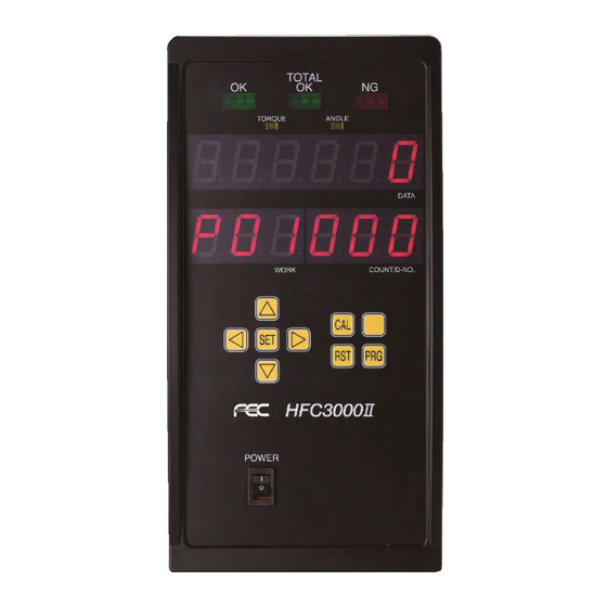
- Page 28 Chapter 3 Part Names 3-1 Controller controller 3-1-1 Controller controller Front Panel TOTAL OK OK (ACCEPT) NG (REJECT) Lights up when Lights up when the Lights up when even acceptable (OK) fastening results are fastening results are one of the preset within the standard obtained for the judgment criteria is not...
- Page 29 Chapter 3 Part Names 3-1-2 controller Rear Panel *RS232C-2 *DATA REPORT ETHERNET For ID data input *Under development T/A MON. TOOL Connector for torque and angle Connector for tool cable monitor output connection. connection. (PAGE 4-18) Twist lock type connector. Can be connected and disconnected by twisting by 90 degrees.
-
Page 30: Tools
Chapter 3 Part Names 3-2 Tools 3-2-1 Angle Tool Hand-held type fastening tool provided with angle head, planetary gear, torque transducer, servomotor, indicator LEDs, and operating switches. Tool cable connector ②Reversing switch High-speed servomotor Torque transducer and ①Starting switch planetary gear ③LEDs for judgment and status indications Angle head ①Starting switch: When the switch is turned ON (by pressing), the tool tip rotates for performing... -
Page 31: Pistol Tool
Chapter 3 Part Names 3-2-2 Pistol Tool Pistol type hand-held type fastening tool provided with planetary gear, torque transducer, servomotor, indicator LEDs, and operating switches etc. High-speed servomotor Torque transducer and planetary gear ②Reversing switch ③LEDs for judgment and status indications ①Starting switch Tool cable connector... - Page 32 Chapter 3 Part Names Memo PAGE 3-6...
- Page 33 Chapter 4 Installation Chapter 4 Installation PAGE 4-1...
-
Page 34: Unit Rear Panel
Chapter 4 Installation 4-1 Installation Procedure Follow the installation procedures of the Hand System in the order prescribed below. № Item Contents Page Mount the controller with reference to the outer ① Installation shape. PAGE 4-2 Connection of input power Wiring connection by cable provided as accessory to ②... - Page 35 Chapter 4 Installation 4-2 controller Outer Shape and Installation Dimensions Mounting: 4 points (Rear panel) M6 screws: Use screws with a length equivalent to the installation plate thickness +9mm. Weight: 8.5 kg <Mounting Precautions> ◆ Do not install the unit at a location that is constantly vibrating. ◆...
-
Page 36: Input Power Source Connection
Chapter 4 Installation 4-3 Input Power Source Connection Connect the dedicated power cable to the connector at a lower portion of the rear panel of the controller. A power cable is provided as standard. Primary power connector PAGE 4-4... -
Page 37: Tool Cable Specifications
Chapter 4 Installation 4-4 Tool Cable Specifications ■Tool Cable (Cable type: FEB-1616-M**) Total length L Controller side Tool Side ■Tool Cable (Cable type: C15-F7-M**) Total length L Tool Side Controller Side (AWG16-4/AWG24-24) (#22 shell-19) PAGE 4-5... -
Page 38: External Control Signal Connection
Chapter 4 Installation 4-5 External Control Signal Connection DI0 Terminal Block: TB1,2,3 TB3 12 TB3: 12 terminals *The No. 11 terminal at the plug side lacks a projection TB3 1 TB2 12 TB2: 12 terminals TB1: 12 terminals TB2 1 *The No. - Page 39 Chapter 4 Installation 4-5-1 controller I/O Signals [BANK SELECT = OFF] Pin No. Signal IN/OUT Description of Function/Usage TB3-1 IN COMMON Common input signal (bipolar) TB3-2,11 +24V +24V output Service power When use this power supply, please use a shielding 0.5Amax supply line.Wire it from the noise source apart.
- Page 40 Chapter 4 Installation 4-5-2 controller I/O Signals [BANK SELECT = ON] The following output changes. Pin No. Signal IN/OUT Description of Function/Usage TB1-12 BANK SELECT=[ON] IN-12(NO) Bank select signal (for WORK SELECT return signal) WORK OUTPUT BIT 2 TB3-7 OUT-6(NO) When BANK SELECT=[ON], return output of the select signals Note 1) of WORK SELECT BITS 2 and 3 is performed.
-
Page 41: Input And Output Circuit Specifications And Recommended Connection Circuit
Chapter 4 Installation 4-5-3 Input and Output Circuit Specifications and Recommended Connection Circuit Unit I/O circuit DC power source Input circuit PLC output circuit Input signal Input signal PLC input circuit Output circuit Output signal Output signal *The above diagram shows an NPN type connection example. ・The I/O hardware accommodates both positive and negative polarities and both NPN (sink ・... -
Page 42: Description Of I/O Signals
Chapter 4 Installation 4-5-4 Description of I/O Signals +24V、GND: SERVICE POWER SUPPLY PIN No.: TB3-2,3,11,12 Do not supply power to the [+24V] and [GND] terminals (24V DC service power supply) on the controller. Doing so may cause damage to the product.Do not use it more than 0.5A. When use the service power supply;... - Page 43 Chapter 4 Installation BATCH OK RESET: BATCH COUNTER RESET SIGNAL PIN No.: TB3-5 When a change of WORK has been selected at the terminal block, the current cycle count value is cleared by input of this reset signal. When a change of WORK has been selected at the controller indicator panel, the current cycle count value is cleared by input of this reset signal.
- Page 44 Chapter 4 Installation WORK SELECT 0 ~ 4: Work Select Signals PIN No.: TB1-7 ~ 11 A Work No. among 32 types can be selected by a combination of the signals WORK SELECT 0 ~ WORK SELECT 4 (selection from among 64 types of work is not accommodated). WORK SELECT 4 WORK SELECT 3 WORK SELECT 2...
- Page 45 Chapter 4 Installation [Output Signals] When an output signal is “ON,” the voltage at the corresponding output terminal is at the same level as the output common voltage (0V). As shown below, the output signal at each terminal takes on one of two meanings in accordance with the combination with the BANK SELECT signal (output bank).
- Page 46 Chapter 4 Installation OUTPUT BANK [OFF] NG: FASTENING NG (FAILURE) SIGNAL PIN No.: TB2-1 OUT-1 The “ON” output is performed when an abnormal exit occurs with a fastening result falling outside a judgment range. OK: FASTENING OK SIGNAL PIN No.: TB2-2 OUT-2 The “ON”...
- Page 47 Chapter 4 Installation OUTPUT BANK [ON] UNUSED PIN No.: TB2-2, TB2-3 OUT-2~3 These are unused. WORK OUTPUT 0 ~ 4: WORK SELECTION INPUT CHECK The input signals, WORK SELECT 0 ~ 4, are returned as they are as the output signals, WORK OUTPUT 0 ~ 4.
-
Page 48: Timing Chart
Chapter 4 Installation 4-5-5 Input/output signal timing chart ●Basic control signals Controller Power Input signal Work Select Torque Curve Output signal Axis Judgment RS232C Output *1) WORK SELECT requires a response time of 100 msec or more after the READY signal ON is output until the START signal is input. - Page 49 Chapter 4 Installation ●MANREV signal timing chart BANK Output Fastening Fastening Reverse Reverse PAGE 4-17...
-
Page 50: External Monitoring Device Signal
Chapter 4 Installation 4-6 External Monitoring Device Signal External monitor signals are output from the MONITOR connector on the controller bottom. MONITOR Compatible connector D-SUB 9-pin plug Inch thread (#4-40) External monitor signal specifications Pin No. Signal Description IN/OUT Disabled Disabled ANGLE PULSE Angle pulse monitor output... - Page 51 Chapter 4 Installation How to Calibrate the External Monitoring Device When the CAL switch of the controller indicator is pressed while “1” is indicated at the D-No. indication part of the indicator in the real time mode, the CAL voltage is output at a potential difference of approximately Δ3.75V from TORQUE OUT and, at the same time, the torque value recognized by the controller is indicated at the upper indication part.
-
Page 52: Rs-232C Interface Signal
Chapter 4 Installation 4-7 RS-232C Interface Signal 4-7-1 RS232C Specifications (RS232C-1) Compatible connector D-SUB 9-pin socket Inch thread (#4-40) RS232C-1 RS232C Communication Specifications Synchronization Communication Start-stop 9600bps (fixed) Method synchronization method Speed Communication Data Length/Start Half-duplex system 8 bits/1 bit/None/2 bits (fixed) Mode Bit/Parity/Stop Pin No. -
Page 53: Data Format (Rs232C-1)
Chapter 4 Installation 4-7-2 Data Format (RS232C-1) The fastening result data are output from the RS232C-1 interface at the end of fastening. The data length of the fastening result data in ASCII format is 79 bytes (corresponding to 79 characters) per single fastening operation. - Page 54 Chapter 4 Installation When the fastening judgment is NG (REJECT) (JDG: Judgment, OCR: Occurrence) COUNT No. ACCEPT AXIS No. WORK No. COUNT 39H 39H PEAK TORQUE FINAL ANGLE 20H 31H SIGN SIGN FINAL TORQUE RATE1 20H 31H 30H 2EH SIGN RATE2 RATE3 30H 2EH...
-
Page 55: Ethernet Interface
Chapter 4 Installation 4-8 Ethernet Interface The Ethernet interface is the TCP/IP Ethernet port dedicated to communication with the HFC3000 ® User Console installed in a PC with Windows A commercially available LAN cable (cross/straight) can be used as the cable. - Page 56 Chapter 4 Installation Memo PAGE 4-24...
- Page 57 Chapter 5 Power Activation and Operational Tests Chapter 5 Power Activation and Operational Tests PAGE 5-1...
-
Page 58: Items To Be Checked Before Power Activation
Chapter 5 Power Activation and Operational Tests 5-1 Items to be Checked Before Power Activation (1) Check connection between tool and Controller Connect the cable between the tool and the controller securely. If there is a movable part in the path of the cable, check whether or not the cable receives stress by actually moving the movable part. -
Page 59: Items To Be Checked When Activating The Equipment
Chapter 5 Power Activation and Operational Tests 5-2 Items to be Checked When Activating the Equipment Confirm that the indications on the indicator change as follows when the control power is activated. RUN Mode Power activation All segments are lit for approx. -
Page 60: Input Initial Setting Data
Chapter 5 Power Activation and Operational Tests 5-3 Input Initial Setting Data After checking all of the check items of the previous section and activating the power, input the data necessary for performing fastening. Although initial setting data based on the customer’s specifications are input at the time of shipment, if the setting data need to be changed, please refer to “Chapter 6 Description of Operations.”... - Page 61 Chapter 6 Description of Operations Chapter 6 Description of Operations PAGE 6-1...
-
Page 62: Changing Between Run And Program Modes
Chapter 6 Description of Operations 6-1 Changing between RUN and PROGRAM Modes There are two modes to the Handheld tool - the RUN (operation) and PROGRAM (setting) modes. In the RUN (operation) mode, the fastening operation and the fastening result judgment are indicated. Parameters can be changed in the PROGRAM (setting) mode. - Page 63 Chapter 6 Description of Operations (1) Operation/Check Switches ①CAL key switch: CAL voltage check When this switch is pressed, a check of the torque transducer of the tool is performed. The calibration torque value is indicated at the “DATA” indication part. If as a result of the check, the value is within the specified ranges, the LED of the tool flahses alternately in green <-->...
- Page 64 Chapter 6 Description of Operations (4) Tool This is a pistol type hand-held type fastening tool provided with planetary gear, torque transducer, servomotor, indicator LEDs, and operating switches etc. High-speed servomotor Torque transducer and planetary gear ③LEDs for judgment and status indications ①Starting switch ②Reversing switch...
-
Page 65: Run Mode
Chapter 6 Description of Operations 6-2 RUN Mode When the power is activated (turned ON) and the initial process ends, the operation enabled mode (RUN mode) is entered. In the RUN mode, mainly the fastening results, abnormality status, Axis No., parameters, etc., are indicated. -
Page 66: Changing Modes In The Run Mode
Chapter 6 Description of Operations 6-2-1 Changing Modes in the RUN Mode In the RUN mode, selection among the five modes can be performed by pressing the [◄] or [►] switch. Further, in modes other than “Operation View,” the indicated content can be changed by pressing the [▲] or [▼] switch. - Page 67 Chapter 6 Description of Operations 6-2-2 Indications in the RUN Mode Real time Mode In the real time mode, [Mon.] is indicated on the WORK Indication Part. The value in the COUNT/D-No. indication part is incremented or decremented with the [▲] or [▼] switch to change the indicated content.
- Page 68 Chapter 6 Description of Operations ● List of Contents Indicated in the Real Time Mode COUNT/ contro WORK DATA D-NO llers [Torque Value Indication] The load that is currently applied to the torque transducer is indicated in real time. When the [CAL] switch is pressed, the torque value converted in terms of the calibration torque is output.
- Page 69 Chapter 6 Description of Operations [Tool Response•G. Gyrosensor Shake Detection Angle] -2048° ~ +2047° [Tool Command•Ct1.] (0~255) Digit CAL ON, GYRO RESET, etc. [Tool Command•Ct2.] (0~255) Digit Angle conversion constant (fixed at 67) [Tool Command•LEd.] (0~255) Digit LED-related command [Tool Command•BuZ.] (0~255) Digit Buzzer-related command [Tool Command•Gan.
- Page 70 Chapter 6 Description of Operations 6-2-3 Indications in the RUN Mode Fastening Result Mode In the fastening result mode, “r” is indicated at the 100s digit of the WORK indication part and the parameter No. (01 ~ 64) of the fastening operation that was performed is indicated by the 10s and 1s digits.
- Page 71 Chapter 6 Description of Operations ● List of Contents Indicated in the Fastening Result Mode COUNT controller WORK DATA /D-NO N•m Peak torque Final angle N•m /deg Rate 1 H/L N•m /deg Rate 2 H/L N•m /deg Rate 3 H/L 1st timeH/L 2nd time H/L Cycle time...
- Page 72 Chapter 6 Description of Operations 6-2-4 Indications in the RUN Mode Parameter Setting Mode In the parameter setting mode, “P” is indicated at the 100s digit of the WORK indication part and the parameter No. (01 to 64) is indicated by the 10s and 1s digits. The D-No. indication part is changed by pressing the [▲] or [▼] switch and the content of the data No.
- Page 73 Chapter 6 Description of Operations 6-2-5 Indications in the RUN Mode System Setting Mode In the system setting mode, “SYS.” is indicated in the WORK indication part. The D-No. indication part is changed by pressing the [▲] or [▼] switch and the content corresponding to No.
- Page 74 Chapter 6 Description of Operations 6-2-6 Indications in the RUN Mode Operation View In the operation view, the currently selected work (parameter) No. (01 ~ 64) is indicated in the WORK indication part. The Axis No. of the controller is indicated by the 10s and 1s digits of the COUNT/D-No.
- Page 75 Chapter 6 Description of Operations Also, during the fastening operation, the operation speed and the fastening step state are indicated. In the indication during the fastening operation, the parameter No. (01~ 64) that is currently put in operation is indicated in the WORK indication part. The mode cannot be changed in the indication during the fastening operation.
-
Page 76: Program Mode
Chapter 6 Description of Operations 6-3 PROGRAM Mode The parameter settings can be changed in the PROGRAM mode. The Data No. and parameter of each parameter No. are indicated on the indicator. Indicator (PROGRAM Mode) DATA indication part COUNT/D-No. indication part WORK indication part ●DATA indication part The set value (parameter) is indicated. - Page 77 Chapter 6 Description of Operations Set Value Selection Mode 6-3-2 Indications in the PROGRAM Mode Immediately after changing to the “Set Value Selection Mode,” the cursor (flashing number) is indicated in the WORK indication part when the [◄] switch is pressed and is indicated in the COUNT/D-No.
- Page 78 Chapter 6 Description of Operations In the set value selection mode, “SYS.” is indicated in the WORK indication part in the case of a system parameter and the parameter No. (01 to 64) is indicated in the WORK indication part in the case of a fastening parameter.
- Page 79 Chapter 6 Description of Operations 6-3-3 Indications in the PROGRAM Mode Set Value Editing Mode Immediately after changing to the “Set Value Editing Mode,” the cursor (flashing number) is indicated in the upper stage of the indication part. When the [▲] or [▼] switch is pressed, the numerical value at the cursor position changes by ±1.
- Page 80 Chapter 6 Description of Operations ●System Parameter Setting Method A parameter with which [SYS] is indicated in the COUNT/D-No. indication part is a system parameter and its set value is changed by editing the set value, then pressing the [SET] switch, thereafter changing the indication of “NO”...
-
Page 81: Copying Of Parameters/Erasure Of The Fastening Result Record/Formatting Of The Cf Card
Chapter 6 Description of Operations 6-4 Copying of Parameters/Erasure of the Fastening Result Record/Formatting of the CF Card In setting the contents of multiple parameter Nos., a certain parameter No. can be copied to another parameter No. in the set value editing mode. Parameters can be copied by the following operation procedures. - Page 82 Chapter 6 Description of Operations Similar operations can be performed from “ErASE,” with “021” indicated in the D-No. indication part, to erase all fastening result record stored in the controller. ・ Be careful in executing erasing operation because data cannot be recovered after the fastening result record is erased.
-
Page 83: Fastening Ng (Failure) Result Indications
Chapter 6 Description of Operations 6-5 Fastening NG (Failure) Result Indications When a fastening NG occurs, in addition to the NG lamp indication at the upper part of the controller, the item detected as the fastening NG is indicated in the numerical value indication part by the present function. In the case of fastening to the standard torque, judgments are made in the order: rate high/low limits, differential angle high/low limits, 2ND region fastening high/low limit times, angle high/low limits, peak torque high/low limits, and final torque high/low limits, and the item with which NG is detected first is indicated. -
Page 84: Example Of Fastening Ng Item Indication
Chapter 6 Description of Operations 6-5-1 Example of Fastening NG item indication 1. Torque High Limit Judgment High limit peak torque NG Cause: Seizing or locking of the screw Torque inhibit limit NG Cause: Work fault, socket fault 2. Angle High Limit Judgment High limit angle NG Cause: Elongation of screw. - Page 85 Chapter 6 Description of Operations 4. Fastening Time High Limit Judgment High limit 1ST time NG Cause: Tapping fault of object of fastening, bolt thread fault Detachment of socket High limit 2ND time NG Cause: Elongation of bolt Cutting of bolt Detachment of socket 5.
-
Page 86: Ng Judgment
* High and Low Limit Standard Values for Output Judgment The high and low limit values of the HFC3000 System are as follows. ・High limit standard value (REJECT): A value exceeding the high limit standard value ・High limit standard value (ACCEPT): A value that is no more than the high limit standard value... - Page 87 Chapter 6 Description of Operations The following judgments cannot be made unavailable. ・Peak torque check ・Final angle check ・Timeout check Caution ●Torque Check [N•m] •Peak Torque The high and low limit values of the peak torque in the fastening operation are set. The fastening operation is ended when the peak torque high limit value is exceeded during the fastening operation.
- Page 88 Chapter 6 Description of Operations ●Angle Check [deg] •Final Angle The high and low limit values of the angle from the point of Snug torque detection to the end are set. The fastening operation is ended when the angle high limit value is exceeded during the fastening operation.
- Page 89 Chapter 6 Description of Operations ●Rate Check Three rates can be used to monitor the fastening operation during the fastening operation. A rate start torque (angle) and a rate end torque (angle) are set and the torque slope (slope of the torque vs.
- Page 90 •If the rate end torque (angle) cannot be detected during the fastening operation. •Whether torque or angle is used as the rate start (end) point is set by the fastening parameter D-No. 005 [Fastening Judgment Output 3]. ●FUSION/HFC3000 Fastening Parameter (Rate) Correspondence Table FUSION HFC3000...
- Page 91 Chapter 6 Description of Operations Differential Angle Check After the end of fastening, the differential angle, which is the difference between the seating point (angle) of the final torque and the seating point (angle) calculated from the rate 2, is measured and judged.
- Page 92 Chapter 6 Description of Operations Break away Torque Check Whether or not the torque value during reverse rotation is within the high limit ranges is judged. When D-No. 110 [Reverse Torque High Limit] is exceeded, the fastening operation is ended and the abnormal state signal A09-08 “Reverse Torque Error”...
- Page 93 Chapter 6 Description of Operations Current Value Warnings After the end of the fastening operation, it is judged whether or not the peak current value during operation is within the high and low limit ranges. If the peak current value during operation falls below the low current limit or exceeds the high current limit, although the controller outputs the ACCEPT axis judgment, the PLC layout output signal “Multi: Current Limit Warning,”...
- Page 94 Fastening Speed and Time With the HFC3000 Nutrunner System, the speed can be set according to the fastening operation. 1. Within the set 1st time high limit value, fastening up to the 1st torque or the 1st angle is performed. Also within the 1st time, the following fastening operations are executed.
- Page 95 Chapter 6 Description of Operations 2. When the 1st torque or the 1st angle is detected, the 1st time ends and the 2nd time is started. The 1st torque and the 1st angle are the points of changing from the 1st speed to the 2nd speed and are the points of synchronization of the 2nd step.
-
Page 96: Parameter Structure
Chapter 6 Description of Operations 6-6 Parameter Structure Parameter No. SYS System Parameters 000: Torque Unit 001: Software Version 002: Amplifier Version 003: System Indication 503:Touch Panel Connection Port Number Parameter No. P. 64 Parameter No. P. 63 Parameter No. P. 62 Parameter No. - Page 97 Chapter 6 Description of Operations System Parameters <System Parameters> Par No. Indication: SYS Setting controller Item D-No. Contents change Torque controller Software Version Amplifier Version System Indication ○ Spindle Adapter Gear Ratio For Adjustment by the Manufacturer For Adjustment by the Manufacturer Communication Axis Indication Axis Cycle Count (×1 million) Axis Cycle Count (×1)
- Page 98 Chapter 6 Description of Operations Setting contro Item D-No. Contents change llers Connected Tool No. Connected Tool Information “015-P1” Connected Tool CAL Torque Decimal Point Position Connected Tool CAL Torque Connected Tool CAL Voltage Connected Tool ZERO Voltage Connected Tool Internal Gear Ratio (×100) Connected Connected Tool Serial No.
- Page 99 Chapter 6 Description of Operations Setting contro Item D-No. Contents change llers CF Card Storage Capacity RS232C-2 Communication Speed RS232C-2 Parity RS232C-2 Stop Bit RS232C-2 Word Length Option Information2 Not used Not used Not used Not used ID Input Selection ○...
- Page 100 Chapter 6 Description of Operations System Parameters (controller Information 1) D-No.000 Torque controller Cannot be changed. All fastening parameters within the controller will have the same torque unit. D-No. 001 Software Version Cannot be changed. This is the software version of the controller. D-No.
- Page 101 Chapter 6 Description of Operations D-No.010 controller Maximum Current Cannot be changed This indicates the maximum current value of the controller. D-No. 011 IP Address (upper 6 digits) D-No. 012 IP Address (lower 6 digits) Setting range: 0 ~ 255 The IP address is set here.
- Page 102 Chapter 6 Description of Operations D-No.026 controller SW1 Setting State D-No.027 controller SW2 Setting State The setting states of the switch on the controller inside (the SW1 switch on the controller front panel and the SW2 switch on the controller bottom panel) are indicated. D-No.026 D-No.027 The ON/OFF states of SW No.
- Page 103 Chapter 6 Description of Operations System Parameters (Options) D-No.033 System Option 1 Standard setting: 000000 Optional functions of the controller are set here. *****1: Accept Relay output (0:level/1:pulse) ・Set to “1” if the QL-OK output signal of the standard IO is to be in pulse form. ****1*: Total Accept Relay Output (0:level/1:pulse) ・Set to “1”...
- Page 104 Chapter 6 Description of Operations D-No.034 System Option 2 Standard setting: 000000 Optional functions of the controller are set here. *****1: WORK change (0: Display panel/1: PLC I/O Signal) ・Set to “1” if the change of WORK is to be performed from the external I/O (the change cannot be performed from both the operation panel and the external I/O) ****1*: Reversing switch (0: Slide/1: Push Button) ・Slide: P type, T type/Pushbutton: A type, S type...
- Page 105 Chapter 6 Description of Operations D-No.100 Connected Tool No. The tool No. corresponding to the tool model is indicated. Please refer to “Tool Models.” D-No.101 Connected Tool Information The maximum torque and motor capacity of D-No. 100 “Connected Tool No.” are indicated. D-No.102 Tool CAL Torque Decimal Point The decimal point position of the torque value of D-No.
- Page 106 Chapter 6 Description of Operations D-No.200 controller Setup Tool No. Setting range: Tool No. registered for the model The Tool No. of the connected tool is set with reference to “Tool Models.” When the unit setup tool No. is changed, initialization and automatic correction of the fastening parameter set values are performed.
- Page 107 Chapter 6 Description of Operations D-No.300 Connected Fieldbus Information The type of fieldbus installed on the Expansion controller 1 is indicated. Expansion Unit 1 Uninstalled (Standard IO) MFC-DT MFC-CC Installed Installed (CC-Link) (Expansion IO) MFC-PB Installed MFC-DN (PROFIBUS Installed DP-V1) (DeviceNet) MFC-EN Installed MFC-PN Installed...
- Page 108 Chapter 6 Description of Operations D-No.304 Communication Speed Setting range: 0 ~ 4 (CC-Link, DeviceNet) The communication speed of the fieldbus set in the controller is indicated. System Parameter D-No.304 Fieldbus Type CC-Link 156kbps 625kbps 2.5Mbps 5Mbps 10Mbps DeviceNet 125kbps 250kbps 500kbps D-No.305 Occupied Stations Setting range: 1 ~ 4 (CC-Link)
- Page 109 Chapter 6 Description of Operations D-No.312 IP Address (upper 6 digits) D-No.313 IP Address (lower 6 digits) Setting range: 0 ~ 255 (PROFINET IO, EtherNet/IP) The IP address of the fieldbus set in the controller is indicated. D-No.314 Subnet Mask (upper 6 digits) D-No.315 Subnet Mask (lower 6 digits) Setting range: 0 ~ 255 (PROFINET IO, EtherNet/IP) The subnet mask of the fieldbus set in the controller is indicated.
- Page 110 Chapter 6 Description of Operations D-No.400 CF Card Storage Capacity [%] The storable capacity of the CF card is indicated. D-No.401 RS232C-2 Communication Speed [bps] The communication speed of the RS232C-2 interface is indicated. D-No.402 RS232C-2 Parity The parity of the RS232C-2 interface is indicated. D-No.403 RS232C-2 Stop Bit [bit] The stop bit of the RS232C-2 interface is indicated.
- Page 111 Chapter 6 Description of Operations D-No. 500 IP Address (upper 6 digits) D-No. 501 IP Address (lower 6 digits) Setting range: 0 ~ 255 The IP address of the touch panel connected in the controller is indicated. D-No.502 Touch Panel Function / Language Setup standard setting : 0 Setting range : 0~4 Disabling/enabling of the touch panel function and the language setting are changed.
- Page 112 Chapter 6 Description of Operations <Fastening Parameters> * Items in colored cells are skipped by the indicator. Torque Angle Item PAR No. D-No. Contents Method Method Fastening Method ○ ○ Fastening Steps ○ ○ Fastening Option P.01~ Fastening ○ ○ Judgment Item 1 Settings P.64...
- Page 113 Chapter 6 Description of Operations Torque Angle Item PAR No. D-No. Contents Method Method ○ ○ Rate 1 Low Limit ○ ○ Rate 1 High Limit ○ ○ Rate 2 Low Limit ○ ○ Rate 2 High Limit ○ ○ Rate 3 Low Limit ○...
- Page 114 Chapter 6 Description of Operations Torque Angle Item PAR No. D-No. Contents Method Method ○ ○ Number of Accept [times] Others P.01~P.64 ○ ○ Angle Head Torque Variation Rate[%] ○ ○ CW Servo Lock Time Between Steps ○ ○ CW Wait Time Between Steps ○...
- Page 115 Chapter 6 Description of Operations Fastening Settings D-No.000 Fastening Method Standard setting: 0 The method used for fastening is set. 0: Torque Method, 1: Angle Method D-No. 001 Fastening Steps Standard setting: 1 The number of steps used in fastening is set. 1: 1-Step Fastening ・...
- Page 116 Chapter 6 Description of Operations Be careful as the fastening judgment is not performed regardless of the values of the high and low limit set values when the settings of the fastening parameters Caution D-No. 003 “Judgment Item 1” and D-No. 004 “Judgment Item 2” are 0. D-No.
- Page 117 Chapter 6 Description of Operations D-No. 004 Judgment Item 2 Standard setting: 000001 Only the change 0 → 1 is enabled. *****1: Timeout Check ・ Whether or not the fastening time from the start of fastening to D-No. 105 [1st Torque] or D-No. 205 [1st Angle] or from D-No.
- Page 118 Chapter 6 Description of Operations D-No.005 After Fastening Operation Standard setting: 000000 *****1: 1 Pulse Reverse ・After the end of fastening, the torque is reversed at the D-No. 121 [1 Pulse Reverse Torque High Limit]. The 1 Pulse Reverse is performed at the D-No. 410 [1 Pulse Reverse Speed] for the D-No.
- Page 119 Chapter 6 Description of Operations D-No.006 Interrupt Operation During Fastening Standard setting: 000000 *****1: Pulse Fastening Operation ・Set this to ON if fastening by pulsing is to be performed (pulsing is started after detection of 1ST). ****1*: Gyro Setup Enable ・With a P type or T type tool, the pause operation functions are enabled when this is set to ON.
- Page 120 Chapter 6 Description of Operations Torque D-No. 100 Calibration Torque [N・m] Setting range: 70% ~ 120% of the standard calibration torque of the tool The calibration torque value of the connected tool is set. In a case where a socket or offset gear, with which a load is applied to the tool top, is connected or in a case where, due to the workpiece characteristics, the indicated fastening result value differs from the result obtained by a fastening torque tester, etc., the fastening torque can be corrected by the setting of the calibration torque.
- Page 121 Chapter 6 Description of Operations [Caution Regarding Fastening] Avoid performing fastening at a torque exceeding the maximum fastening torque of a tool. Caution Also, do not use a tool outside the specified duty cycle (ratio of fastening time and downtime) range, even if the maximum fastening torque is not exceeded. PAGE 6-61...
- Page 122 Chapter 6 Description of Operations D-No. 104 Ramp Down Start Torque [N・m] Setting range: 0 ~ D-No. 100 [Calibration Torque] × 1.0 The torque value at which D-No. 401 [Freerun Speed] is switched to D-No. 402 [1st Speed] is set. However, even if the ramp down start torque is not detected, switching to D-No.
- Page 123 Chapter 6 Description of Operations D-No. 110 Reverse Torque High Limit [N・m] Setting range: 0 ~ D-No. 100 [Calibration Torque] × 1.3 The high limit value of the torque during reverse operation is set. When the reverse torque high limit is exceeded during reverse operation, fastening is stopped and the abnormal state signal A.09-08 “Reverse Torque Error”...
- Page 124 Chapter 6 Description of Operations D-No. 118 Final Torque Low Limit [N・m] Setting range: 0 ~ D-No. 100 [Calibration Torque] × 1.1 D-No. 119 Final Torque High Limit [N・m] Setting range: 0 ~ D-No. 100 [Calibration Torque] × 1.3 The low and high limit values of the torque at the end of fastening are set. ・...
- Page 125 Chapter 6 Description of Operations Angle D-No. 200 Final Angle Low Limit [deg] D-No. 201 Final Angle High Limit [deg] Setting range: 0 ~ 9999.9 The low and high limit values of the output judgment angle are set. When the fastening angle exceeds the final angle high limit or falls below the final angle low limit, the REJECT axis judgment is made.
- Page 126 Chapter 6 Description of Operations Rate D-No. 300 Rate 1 Low Limit [N・m/deg] Setting range: - maximum torque rate of tool ~ maximum torque rate of tool The low limit value of the slope of torque vs. angle between the two points of D-No. 112 [Rate 1 Start Torque] ~ D-No.
- Page 127 Chapter 6 Description of Operations Time D-No. 310 Initial Time [sec] Setting range: 0.0 ~ 999.9 The time for shock relaxation, fitting of the bolt and socket, etc., at the start of fastening is set. Operation at D-No. 400 [Initial Speed] is executed during the initial time or during D-No. 500 [Freerun Revolutions].
- Page 128 Chapter 6 Description of Operations Speed ・ The minimum tool rotation speed and the maximum tool rotation speed differ according to the tool model. Caution Please refer to “Tool Models” regarding the allowed input range. D-No. 400 Initial Speed [rpm] Setting range: Minimum tool rotation speed to maximum tool rotation speed The speed for impact relaxation, fitting of the bolt and socket, etc., at the start of fastening is set.
- Page 129 Chapter 6 Description of Operations D-No.405 Reverse 1 Speed [rpm] Setting range: Minimum tool rotation speed to maximum tool rotation speed The speed during reverse operation is set. This is the reverse speed at which rotation is performed while the REV. switch of the indicator is pressed.
- Page 130 Chapter 6 Description of Operations Revolutions/Current D-No. 500 Freerun Revolutions [rev.] Setting range: 0 ~ 99.9 The number of revolutions, from the start of fastening, at which switching to D-No. 402 [1st Speed] is performed is set. However, even if the freerun revolutions are not reached, switching to D-No. 402 [1st Speed] is performed when D-No.
- Page 131 Chapter 6 Description of Operations Time D-No.540 Number of Accept [times] Setting range: 0~99 This designates the number of times of fastening and when fastening OK is issued for the number of times designated by the cycle count, the batch OK is output. D-No.541 Angle Head Torque Variation Rate [%] Initial value: 0, Setting range: 0~100 When reaching the Standard Torque and the monitored curve variation of the torque curve shows...
- Page 132 Chapter 6 Description of Operations D-No.546 Reverse Ramp Up Time [msec] Setting range: 100~5000, Standard setting: 500 The time constant for acceleration from zero speed to the maximum rotation speed of the tool in reverse rotation operation is set. The reverse ramp up time is used in the following cases. ・Manual reverse by raising (“OFF”→”ON”) of the PLC I/O input signal “REVERSE.”...
- Page 133 Chapter 6 Description of Operations Pulsing D-No.006 Interrupt Operation During Fastening : Pulse Fastening Operation ON Set value: xxxxx1 By setting “1” for Pulse Fastening Operation ON as Data No. 006 Fastening Interrupt Operation, the pulse fastening operation is performed from after the detection of the 1st torque (D-No. 105) to the attainment of the standard torque (D-No.
- Page 134 Chapter 6 Description of Operations D-No.552 Pulse Fastening Stop Servo Lock Time [msec] Initial value: 5, Setting range: 0~200 Immediately after the fastening is paused, a servo lock is applied for the set amount of time to relax the stop shock. D-No.553 Pulse Fastening Wait Time [msec] Initial value: 15, Setting range: 0~200 The time until rotation is started again from the point at which fastening is paused is set.
- Page 135 Chapter 6 Description of Operations Gyro D-No.006 Interrupt Operation During Fastening : Gyro Setup Enable ON Set value: xxxx1x By setting “1” for Gyro Settings Available ON as data No. 006 Interrupt Operation During Fastening, a gyro pause operation is performed from after the detection of the 1st torque (D-No. 105) to the attainment of the standard torque (D-No.
- Page 136 *For continuous sequence, the waveform data for each stage (except for at the end of fastening) cannot be read or saved via the HFC3000 user console. (Only the torque-angle waveform (540deg fixed) is saved in the waveform history or the CF card.) ・Axis cycle count is incremented at the final stage.
- Page 137 Chapter 6 Description of Operations [1: Batch Sequence] The parameter No. and count are set for the operation at each stage (the intermission time is not used). If the setting is [02. 05. □□], after the fastening operation using parameter 2 is counted 5 times, the next stage is entered (a fastening operation is counted only when the ACCEPT judgment is made).
- Page 138 Chapter 6 Description of Operations <Program Examples2> Automatic Function: For each stage, six digits of data are used to designate the parameter No. and the intermission time. 0 1 . 0 0 . 0 5 The intermission time is executed after completion of fastening. Fastening parameter No.
- Page 139 Chapter 6 Description of Operations Memo PAGE 6-79...
- Page 141 Chapter 7 Troubleshooting Chapter 7 Troubleshooting PAGE 7-1...
-
Page 142: Abnormal State Display
Chapter 7 Troubleshooting 7-1 Abnormal State Display When an error occurs in the tool or the controller, the abnormal state No. is indicated in the WORK part and the sub code is indicated in the COUNT/D-No. part of the indicator. Abnormal state signal indication Sub code indication Abnormal State No. -
Page 143: Abnormality Details/Causes And Recovery Methods
Chapter 7 Troubleshooting 7-2 Abnormality Details/Causes and Recovery Methods ・ When an abnormality occurs, remove the cause and ensure safety before restarting operation. ・If a critical error occurs in the controller, the abnormal state number is not indicated and Caution the [CONTROL POWER LED] of the controller lights up in red. - Page 144 Chapter 7 Troubleshooting A.03: TOOL ID Error Description/Cause Recovery Method Indication 1. Inspect the tool cable. ID Data Error 2. Breaking or malfunction of the tool cable or A.03-01 There is an error in the ID data in the tool may have occurred. the preamplifier.
- Page 145 Chapter 7 Troubleshooting A.04: System Memory Error (contd.) Description/Cause Recovery Method Indication RTC Write Error 1. Turn the control power OFF and then turn A.04-06 Writing of settings into the RTC ON the power again after waiting for at failed. least 5 minutes.
- Page 146 Chapter 7 Troubleshooting A.08: Servo Amplifier Error Description/Cause Recovery Method Indication 1. Ensure that the ambient temperature is 0 ~ 45°C. Over Heated Error 2. Ensure that the duty cycle conforms to the The servo drive circuit does not A.08-01 specified range.
- Page 147 Chapter 7 Troubleshooting A.08: Servo Amplifier Error (contd.) Description/Cause Recovery Method Indication Over Speed Error 1. Inspect the tool cable. A.08-08 The controller cannot control the 2. Breaking or malfunction of the tool cable or the tool may have occurred. rotation of the motor.
- Page 148 Chapter 7 Troubleshooting A.09: Setting Data Error Description/Cause Recovery Method Indication If a set value is set to 0 or outside the setting range, set a correct value. [A. 09-02] 102: Peak Torque High Limit=0 312: 1st Time High Limit=0 Missing Parameter Setting 314: 2nd Time High Limit=0 A parameter operation set value is...
-
Page 149: Axis Judgment: Checking The Contents Of The Reject
Chapter 7 Troubleshooting 7-3. Axis Judgment: Checking the Contents of the REJECT When a value falling outside the high and low limit range (falling below the low limit value) of a fastening parameter is detected during a fastening operation, the REJECT axis judgment is made and the NG LED of the controller lights up in red. -
Page 150: Ethernet Communication
Chapter 7 Troubleshooting 7-4. Ethernet Communication If Ethernet communication of the User Console cannot be performed with the PC being used, please refer to the following troubleshooting table and take the necessary measures. Item Countermeasures/Check Details PAGE Is there an error in the TCP/IP PAGE Check the TCP/IP setup procedures. - Page 151 PC’s setting again. Procedure 4. If a normal response is made as in the screen above and yet connection with the HFC3000 User Console fails, make the command prompt screen appear again and then enter “ping 192.168.3.199” or “ping 192.168.3.198.”...
- Page 152 Chapter 7 Troubleshooting 7-5. RTC The HFC3000 controller is equipped with an RTC (real time clock) for holding date and time data. ・Model ANG-RTC ・Backup power source Backup by electric double layer capacitor Backup duration in power OFF state Approx. 1000 hours...
- Page 153 Chapter 8 Options Chapter 8 Options PAGE 8-1...
-
Page 154: Compactflash (Cf) Card
Chapter 8 Options 8-1 CompactFlash (CF) Card Fastening results and fastening curves can be stored as files in a CompactFlash (CF) card (hereinafter, “memory card”). The stored data can be confirmed later by reading with a PC. ・ If an unused memory card or a memory card used in another device is to be used, be sure to use it after formatting it. - Page 155 In regard to the fastening curves, the torque vs. angle (180deg) curve of each axis is stored in the “nracd” format, which is dedicated for use with the HFC3000 User Console. The fastening curve displayed on the “Curve Monitor” of the HFC3000 User Console can be stored in the TSV format.
- Page 156 Chapter 8 Options ●Storage of Fastening Curves Fastening curves are stored in the automatically-generated folder “CURVE.” Inside the “CURVE” folder, folders, each with a name expressing the year and month, such as “201309,” are generated automatically, and a folder is automatically generated in the manner of “201310,”...
- Page 157 Chapter 8 Options When the remaining capacity of the memory card falls to no more than 1%, the CF ACCESS LED lights up in orange. The storable capacity of the memory card can be checked from the indicator. ●Procedures for Confirming the Storable Capacity of the Memory Card 1.
- Page 158 Chapter 8 Options Formatting the Memory Card All data stored in the memory card can be erased by an operation from the indicator. Do not extract the memory card during formatting of the memory card. The card may become damaged and become incapable of use. Caution ●Memory Card Formatting Procedure Procedure 1.
-
Page 159: Expansion Rs232C Interface
Chapter 8 Options 8-2 Expansion RS232C Interface ID data can be input via the expansion RS232C interface. The ID data that have been input are added to the curve and fastening result data and output as result data or to the fieldbus message, etc. Pin No. - Page 160 Chapter 8 Options Memo PAGE 8-8...
- Page 161 Chapter 9 External Interface Chapter 9 External Interface PAGE 9-1...
-
Page 162: Common Specifications
Chapter 9 External Interface 9-1 Common specifications 9-1-1 Fieldbus I/O signal specifications ① HFC3000 [PLC → HFC3000]Input signal specification The input signal fixed layout. Conne Singnal Name Contents ction 0bit 0bit Not USED Always off. 1bit 1bit Not USED Always off. - Page 163 Chapter 9 External Interface ② HFC3000 [HFC3000→PLC]OUT signal specification The output signal fixed layout. Conne Singnal Name Contents ction 0bit 0bit Outputs when N/R operation ends. 1bit 1bit ACCEPT Outputs when fastening result OK. 2bit 2bit REJECT Outputs when fastening result NG.
- Page 164 Chapter 9 External Interface 9-1-2 Message Output Format (Handheld Tool Output → PLC Input) ASCII Code :182 bytes fixed Data Format in BANK : OFF COUNT No. : Incremented by +1 at each fastening ACCEPT COUNT: Counted number of ACCEPT fastening judgments (JDG: Judgment, OCR: Occurrence) ACCEPT Date (Year: Lower 2 digits)
- Page 165 Chapter 9 External Interface Data Format in BANK : ON (JDG: Judgment, OCR: Occurrence) BANK [OFF] [ON ] REJECT Outbreak factor "X"(58H): 1ST TIME 2ND TIME There is it behind the data which REJECT produced first. 1 0 . 0 2...
- Page 166 Chapter 9 External Interface 9-1-3 Fieldbus Setup The fieldbus settings are set in the “Fieldbus Setup” menu of the HFC3000 User Console. The following setting window is displayed when “OPTION” → “Fieldbus Setup” is selected at the menu bar. In the bus select/communication window, selection of the fieldbus type, uploading, downloading, and verification of fieldbus settings with respect to the controller, and browsing and saving of fieldbus settings with respect to the PC can be performed.
-
Page 167: Ethernet/Ip
Chapter 9 External Interface 9-2. EtherNet/IP The HFC3000 EtherNet/IP System conforms to the open field network EtherNet/IP. Control of tools and transactions of message information are executed by EtherNet/IP Explicit message communication. Due to conformance with the open field network EtherNet/IP System, connections with EtherNet/IP devices (master/slave) of other manufacturers are enabled. - Page 168 Chapter 9 External Interface 9-2-2 Hardware Setting Module Status Link/ Activity EtherNet/IP connector Network Status PAGE 9-8...
- Page 169 EtherNet/IP configuration software to connect the MFC-EN and the PLC. The EDS file is included in the installation CD for the HFC3000 User Console. Please refer to the instruction manual for the EtherNet/IP configuration software concerning the appropriate method for using the EDS file.
- Page 170 Chapter 9 External Interface ●List of LED Indications The module LEDs indicate the states of the nodes of the HFC3000 EtherNet/IP System and the network state. Color State Details Offline Offline or power is not supplied. Lit up Online Communicating normally.
- Page 171 32 bytes (256 bits) 8 bytes (64 bits) 4096 bytes 32bytes Setting Standard 16 bytes (128 bits) 8 bytes (64 bits) 200 bytes 32bytes Setting 9-2-4 Fieldbus Setting Please refer to S0140165 HFC3000 Omron PLC EtherNet/IP Connection Guide. PAGE 9-11...
-
Page 172: Cc-Link
Chapter 9 External Interface 9-3. CC-Link The HFC3000 CC-Link System conforms to the open field network CC-Link Ver 2.00. Control of tools and transaction of message information are executed by communication. Due to conformance to the open field network CC-Link Ver 2.00 System, connections with a CC-Link Ver 2.0 master station, Ver 1.10/2.00 remote device stations, and Ver 1.10 remote I/O stations are enabled. - Page 173 Chapter 9 External Interface 9-3-2 Description of the hardware ERR LED CC-Link Connector RUN LED PAGE 9-13...
- Page 174 Chapter 9 External Interface ● Module Pin Configuration 1 2 3 4 5 Signal Wire Color Description Sending side Black Blue Receiving side Signal ground White Shield Ground Manufacturer: Phoenix Contact Type: Connector plug Model: MSTB 2.5/5-ST-5.08 AU M Applicable wire size: AWG 14 ~ 23 or 0.25mm ~ 2.5mm * The connector is provided with the equipment.
- Page 175 Chapter 9 External Interface 9-3-3 I/O Signal Specifications I/O Input/Output Message Input/Output AXIS to PLC PLC to AXIS AXIS to PLC PLC to AXIS Maximum 110 bytes (880 points) 110 bytes (880 points) 88 words 87 words Setting Standard 78bytes (624 points) 78 bytes (624 points) 88 words 87words...
- Page 176 Chapter 9 External Interface 9-3-4 Fieldbus Setup In the CC-Link tab, setting of the Anybus-CompactCom CC-Link is performed. The station No., the communication speed, the number of occupied stations, the extended cyclic setting, and the CC-Link version can be changed. ●Default (the settings are set to the factory settings) ・Station: 1 ・Speed: 10M bps...
- Page 177 Chapter 9 External Interface MELSEC-Q Series Parameter Setting Startup GX Developer Prepare PC Series QCPU (Q mode) Project Parameter Network Parameter Set List of CC-Link 1. Select “Remote Net (Ver. 2 Mode)” at Mode Select. 2. Set the All Connect Count (3) for number of connected Remote Device stations 3.
- Page 178 Chapter 9 External Interface ◆Enabling the CC-Link connection to the PLC In addition, it is necessary for even the PLC side to implement a handshake about the system area. In a ladder program, explain a method of the setting about three stations 8 times. When 632 (278h) bit eyes (Initial Data Processing Request) of the system area (X domain) are turned on as a program of the PLC in the case of three stations 8 times setting, set it so that 632 (278h) bit eyes (Initial Data Processing Complete) of the system area (Y domain) become ON.
-
Page 179: Profibus Dp-V1
Chapter 9 External Interface 9-4 PROFIBUS DP-V1 The HFC3000 PROFIBUS DP-V1 System conforms to the open field network PROFIBUS DP-V1. Control of tools and transaction of message information are executed by cyclic I/O communication and acyclic message communication. Due to conformance to the open field network PROFIBUS DP-V1 system, connections with PROFIBUS DP-V1 devices (master/slave) of other manufacturers are enabled. - Page 180 DP-V1-compatible device and a separate, individual file exists for each device. The GSD file is necessary for using the PROFIBUS DP-V1 configuration software to connect the HFC3000 and the PLC. The GSD file is included in the installation CD for the HFC3000 User Console.
- Page 181 Chapter 9 External Interface ● List of LED Indications The module LEDs indicate the states of the nodes of the HFC3000 PROFIBUS DP-V1 System and the network state. A: Operation B: Status LED Mode LED Color State Details Offline Offline or power is not supplied.
- Page 182 Chapter 9 External Interface 9-4-4 I/O Signal Specifications I/O Input/Output Message Input/Output AXIS to PLC PLC to AXIS AXIS to PLC PLC to AXIS Maximum 32 bytes (256 points) 32 bytes (256 points) 4096 bytes 32bytes Setting Standard 8 bytes (64 points) 16 bytes (128 points) 200bytes 32 bytes...
- Page 183 Chapter 9 External Interface ●Message Bytes Settings ・[PLC to Axis] Setting range: 0byte ~ 32bytes ・[Axis to PLC] Setting range: 0byte ~ 4096bytes PAGE 9-23...
-
Page 184: Devicenet
Chapter 9 External Interface 9-5 DeviceNet The HFC3000 Device Net System conforms to the open field network Device Net. Control of tools and transaction of message information are executed by Device Net Explicit message communication. Due to conformance to the open field network Device Net System, connections with Device Net devices (master/slave) of other manufacturers are enabled. - Page 185 Chapter 9 External Interface 9-5-2 Description of the Hardware Module Status DeviceNet Connector Network Status ● EDS File An EDS file is an information file related to the communication specifications of Device Net-compatible device and a separate, individual file exists for each device. The EDS file is necessary for using the Device Net configuration software to connect the MFC-DN and the PLC.
- Page 186 Chapter 9 External Interface ● Module Pin Configuration 1 2 3 4 5 Signal Wire Color Description Black Power cable - side CAL L Blue Communication data Low side SHUELD Shield CAL H White Communication data High Power cable + side Manufacturer: Phoenix Contact Type: Connector plug Model: MSTB 2.5/5-ST-5.08 AU M...
- Page 187 Chapter 9 External Interface 9-5-3 I/O Signal Specifications I/O Input/Output Message Input/Output AXIS to PLC PLC to AXIS AXIS to PLC PLC to AXIS Maximum 32 bytes (256 points) 8 bytes (64 points) 4096 bytes 32 bytes Setting Standard 16 bytes (128 points) 8 bytes (64 points) 200 bytes 32 bytes...
- Page 188 Chapter 9 External Interface ●Setting I/O ・[PLC to Axis] Setting range: 2bytes [16bits] ~ 8bytes[64bits] ・[Axis to PLC] Setting range: 2bytes [16bits] ~ 32bytes[256bits] ●Message Bytes Settings ・[PLC to Axis] Setting range: 0byte ~ 32bytes ・[Axis to PLC] Setting range: 0byte ~ 4096bytes PAGE 9-28...
-
Page 189: Profinet Io
Chapter 9 External Interface 9-6 PROFINET IO The HFC3000 PROFINET IO System conforms to the open field network PROFINET IO. Control of tools and transaction of message information are executed by cyclic message communication. Due to conformance to the open field network PROFINET IO System, connections with PROFINET IO devices (master/slave) of other manufacturers are enabled. - Page 190 PROFINET IO configuration software to connect the MFC-PN and the PLC. The GSDML file is included in the installation CD for the HFC3000 User Console. Please refer to the instruction manual for the PROFINET IO configuration software concerning the appropriate method for using the GSDML file.
- Page 191 Chapter 9 External Interface ● List of LED Indications The module LEDs indicate the states of the nodes of the HFC3000 PROFINET IO System and the network state. B : Module Status LED A : Network Status LED C : Link...
- Page 192 Chapter 9 External Interface 9-6-4 Fieldbus Setup In the PROFINET I/O tab, setting of the Anybus-CompactCom PROFINET IO is performed. The network settings, the station name, the I/O settings, and the message settings can be changed. ●Default (the settings are set to the factory settings) ・Network Settings IP Address: 192.168.10.50...
- Page 193 Chapter 9 External Interface ●Setting I/O ・[PLC to Axis] Setting range: 2bytes[16bits] ~ 8bytes[64bits] ・[Axis to PLC] Setting range: 2bytes[16bits] ~ 32bytes[256bits] ●Message Bytes Settings ・[PLC to Axis] Setting range: 0byte ~ 32bytes ・[Axis to PLC] Setting range: 0byte ~ 4096bytes PAGE 9-33...
- Page 194 Chapter 9 External Interface PAGE 9-34...
- Page 195 Appendix List of Tool Models...
- Page 196 ◆Please use the following forms of tool model and AXIS controller type when order HFT- M - For tools besides those indicated in the table, please contact us. Maximum Minimum Maximum Maximum Tool Rotation Rotation Torque Rate controller Tool Model Speed Speed [N・m/deg]...
Need help?
Do you have a question about the HFC3000 and is the answer not in the manual?
Questions and answers