Table of Contents
Advertisement
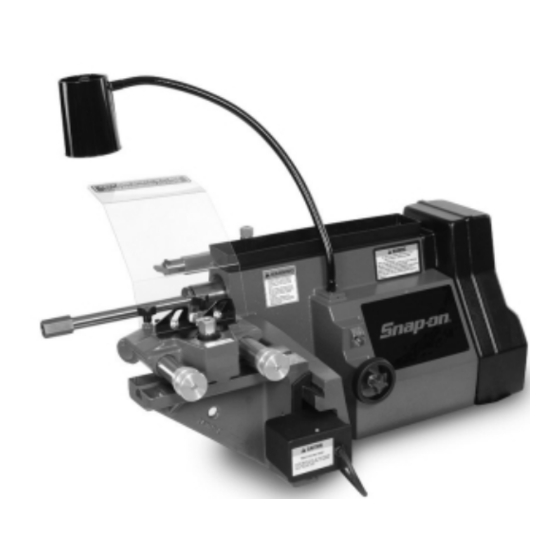
EEBR308A
Brake Lathes
Installation Instructions
Operating Instructions
Safety Instructions
Maintenance Instructions
READ these instructions before placing unit in
service. KEEP these and other materials delivered
with the unit in a binder near the machine for
ease of reference by supervisors and operators.
Advertisement
Table of Contents

Related Manuals for Snap-On EEBR308A

Summary of Contents for Snap-On EEBR308A
- Page 1 EEBR308A Brake Lathes Installation Instructions Operating Instructions Safety Instructions Maintenance Instructions READ these instructions before placing unit in service. KEEP these and other materials delivered with the unit in a binder near the machine for ease of reference by supervisors and operators.
-
Page 2: Important Safety Instructions
16. Secure the work properly to the unit for setup and tool bit positioning. Do not attempt to hold a drum or rotor steady on the arbor with your hands. Both hands must be free to operate unit. SAVE THESE INSTRUCTIONS 2 • Snap-on... -
Page 3: Table Of Contents
Tool Bar Adjustment .....15 Gib Adjustment ......15 Snap-on • 3... -
Page 4: Safety Notices And Decals
• Rotate workpiece before installing on faceplate. cautions in this manual. • Risk of injury due to accidential starting. • Do not use in an area where children may be present. 941134 4 • Snap-on... -
Page 5: Owner's Responsibility
• Do not override safety features. Watch for this symbol! It means BE ALERT! Your safety, or the safety of others, is involved! Snap-on • 5... -
Page 6: Installation
3-prong grounding type plugs and 3-pole receptacles which accept the lathe’s plug. 230 volt lathes use a plug and outlet like those illus- trated in Fig. 3. Replace or repair damaged or worn cords immedi- ately. Figures 2 & 3 6 • Snap-on... -
Page 7: Starting The Lathe
The patented self-aligning spacer prevents diagonal thrust on the adapters. The self-aligning spacer should always be used adjacent to the arbor nut. Snap-on • 7... -
Page 8: Typical Rotor Mounting Configurations
Note: Refer to instructions in adapter kit for mounting Hubless drums and rotors. - 1" Arbor - Arbor Nut - Self-Aligning Spacer - Spacer - Small Double Taper Adapter - Large Double Taper Adapter - Adapter, Used as Spacer Figure 4 8 • Snap-on... -
Page 9: Reconditioning Disc Brake Rotors
The scratch will usually appear as an incomplete cir- cle. This is caused by runout or wobble due to rotor condition, or by the way the rotor is mounted on the arbor. Snap-on • 9... - Page 10 .002" depth-of-cut, for support, and the partially cut 14. Recheck the setting of the depth-of-cut collars, side as needed. which were set to zero earlier by moving the tool bits 10 • Snap-on...
-
Page 11: Reconditioning Brake Drums
Remount the drum and check for runout again. If runout has been corrected, proceed to step 8. Figure 13 Snap-on • 11... - Page 12 19. Repeat steps 15, 16, 17 , and 18. still, and turn the inner dial to zero. Note: Drum—depth-of-cut is determined by the con- dition of the drum: Ovality Flatness (taper, bellmouth, barrel shape) Scoring Diameter (how close to the max. machining limit) 12 • Snap-on...
-
Page 13: Typical Drum Mounting Configurations
1/16 of a turn. DO NOT overtighten the arbor nut. Figure 16 Snap-on • 13... -
Page 14: Maintenance And Service
Handle the adaptors and arbors with care and store them on individual hooks. DO NOT throw them into a box. The adaptors are designed for mounting drums and rotors only, DO NOT misuse the adaptors. 14 • Snap-on... -
Page 15: Spindle Timing Belt Replacement
When the sound boring bar and carefully ease the bar away from the stops, tighten the screws. Clicking is heard when the stop. leadscrew/coupling is not running at a constant veloc- ity. Centering the motor eliminates that problem. Snap-on • 15... - Page 16 Snap-on Tools Company Limited One (1) Year Warranty Snap-on Tools Company (the “Seller”) warrants only to the original purchaser that under normal use, care and service, the Equipment (except as otherwise provided herein) shall be free from defects in material and workmanship for one year from the date of original invoice. Arbor runout is warranted for 30 calendar days from the date of original purchase.
Need help?
Do you have a question about the EEBR308A and is the answer not in the manual?
Questions and answers