Table of Contents
Advertisement
Quick Links
EEBR312A
Brake Lathe
Installation Instructions
Operating Instructions
Safety Instructions
Maintenance Instructions
READ these instructions before placing unit in
service. KEEP these and other materials delivered
with the unit in a binder near the machine for
ease of reference by supervisors and operators.
Advertisement
Table of Contents

Related Manuals for Snap-On EEBR312A

Summary of Contents for Snap-On EEBR312A
-
Page 1: Safety Instructions
EEBR312A Brake Lathe Installation Instructions Operating Instructions Safety Instructions Maintenance Instructions READ these instructions before placing unit in service. KEEP these and other materials delivered with the unit in a binder near the machine for ease of reference by supervisors and operators. -
Page 2: Important Safety Instructions
16. Secure the work properly to the unit for setup and tool bit positioning. Do not attempt to hold a drum or rotor steady on the arbor with your hands. Both hands must be free to operate unit. SAVE THESE INSTRUCTIONS 2 • Snap-on... -
Page 3: Table Of Contents
Model 6950 Twin Cutter ....14 Typical Rotor Mounting Configurations ..15 Set Up and Reconditioning Rotors ..16-18 Snap-on • 3... -
Page 4: Safety Notices And Decals
• Rotate workpiece before installing on faceplate. cautions in this manual. • Risk of injury due to accidential starting. • Do not use in an area where children may be present. 941134 4 • Snap-on... -
Page 5: Owner's Responsibility
• Do not override safety features. Watch for this symbol! It means BE ALERT! Your safety, or the safety of others, is involved! Snap-on • 5... -
Page 6: Before You Begin
3. Apply a light film of oil to all adapters to protect their machined surfaces from rust. Refer to the main- tenance section for more information. 115 VAC 220 VAC Figure 1 - Power Cord Plug and Receptacle Types 6 • Snap-on... -
Page 7: Operating Specifications
Maximum drum depth 9.875” (251 mm) Maximum load 1” Arbor 100 lbs. (45.36 kg) 1.875” Arbor 200 lbs. (90.72 kg) * The no. 906936 Cross Feed Extension – increases the maximum rotor diameter to 19” (483 mm). Snap-on • 7... -
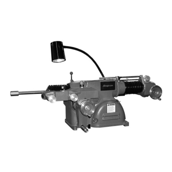
Page 8: Principle Operating Parts
ON/OFF Switch Twin Cutter Cross Feed Handwheel Cross Feed Lock Work Light Draw Bar Oil Dipstick Infimatic ® Variable Feed Gearbox Assembly Drive Motor Pulley Guard Cross Feed Gearbox V-Belt & Speed Belt Tension Adjusting Lever Adjusting Nut 8 • Snap-on... -
Page 9: Arbor Installation
The cross feed may also be operated manu- of each part before use. Wipe each part clean before ally using the cross feed handwheel. and after using it. Carefully correct any flaw with a fine stone. If damage cannot be corrected, replace the part. Snap-on • 9... -
Page 10: V-Belt Tension And Adjustment
3. Push in on the belt approximately 1⁄4” to 1⁄2” Figure 8 – Counterclockwise rotation of handwheels (0.64 to 12.7 mm) and hold. 4. Retighten the adjusting nut. ⁄ ” ⁄ ” Push in Figure 6 – Press the belt in and tighten adjusting nut 10 • Snap-on... -
Page 11: Reconditioning Brake Drums
4. Position the cross slide and spindle by turning their respective handwheels to their maximum clockwise (in) Dial Lock position. Then back off the cross feed handwheel 2 Screw complete turns and the spindle handwheel 4 complete turns. Figure 13 – Set drum diameter measurement Snap-on • 11... -
Page 12: Typical Drum Mounting Configurations
To avoid over- tightening, wrench tighten the arbor nut counterclock- wise until the drum and adapters begin to turn on the arbor, then continue to advance the wrench 1/16 of a turn. DO NOT overtighten the arbor nut. 12 • Snap-on... - Page 13 B. The measured diameter to determine the best amount of material to be removed in one pass. 18. Determine the depth-of-cut by these general guidelines: • Roughing cuts should be no deeper than 0.020". • Finish cuts should be no shallower than 0.004" deep. Snap-on • 13...
-
Page 14: Reconditioning Disc Brake Rotors
2. Secure the twin cutter to the cross feed with self- aligning nut and washer assembly. Tighten the nut firmly. Upper and lower Cross slide self-aligning nut/washer boring bar clamps Twin cutter Cross slide self-aligning nut/washer Figure 16 – Install the twin cutter 14 • Snap-on... -
Page 15: Typical Rotor Mounting Configurations
- 1" Arbor - Arbor Nut - Self-Aligning Spacer - Spacer - Spring - Flange Plate - Flange Plate - Centering Cone - Small Double Taper Adapter - Large Double Taper Adapter - Adapter, Used as Spacer Snap-on • 15... -
Page 16: Set Up And Reconditioning Rotors
WARNING Always wear safety glasses or a face shield. Cutting or grinding on an exposed surface such as a rotor will produce flying chips and debris. 16 • Snap-on... - Page 17 (180°), the rotor may not be properly mounted on the arbor. Remove the rotor and examine the arbor and all adapters for nicks, burrs, chips, dirt, or rust. Inspect the rotor hub for loose or damaged bearing cups. Clean, repair, remount, or replace as necessary. Snap-on • 17...
-
Page 18: Maintenance And Service
Lubricate the cross feed once each month with an automotive chassis grease. Pump the grease into the fitting until clean grease comes out the relief slot at the base of the fitting. 18 • Snap-on... -
Page 19: Cleaning
Remove the dot plug button. Remove the C-clip. Remove the shear gear. Remove any stripped teeth from the drive housing. Install the new gear. The con- cave side of the C-clip faces the gear to maintain pres- sure. Replace the dot plug button. Snap-on • 19... - Page 20 Snap-on Tools Company Limited One (1) Year Warranty Snap-on Tools Company (the “Seller”) warrants only to the original purchaser that under normal use, care and service, the Equipment (except as otherwise provided herein) shall be free from defects in material and workmanship for one year from the date of original invoice. Arbor runout is warranted for 30 calendar days from the date of original purchase.
Need help?
Do you have a question about the EEBR312A and is the answer not in the manual?
Questions and answers