Table of Contents
Advertisement
Available languages
Available languages
Advertisement
Table of Contents

Related Manuals for Radio Zeeland DMP Sigma 120

Summary of Contents for Radio Zeeland DMP Sigma 120
- Page 2 Version: Date: January 28, 2011 Document: Sigma 120 Rev 09 Page 2 of 60 Date 1 release: April 15, 2003...
-
Page 3: Ec Declaration Of Conformity
EN 60945 (IEC 945 Third edition: 1996-11) Chapters 9, 10, 11 and 12 This declaration is issued according to the European Community Directive on Electromagnetic Compatibility (89/336/EEC). On behalf of Radio Zeeland DMP B.V. Terneuzen, the Netherlands Technical Manager 24-06-2002... - Page 4 K2 connection (description) has been changed 23-09-2010 S-120 installation added SIGMA120 software version 9 or higher S-120 software version 3 or higher 28-01-2010 Changed Cover Version: Date: January 28, 2011 Document: Sigma 120 Rev 09 Page 4 of 60 Date 1 release: April 15, 2003...
-
Page 5: Table Of Contents
Dipswitch settings on the PCB of the RZ 1958/Ax .............. 24 3.4. Dipswitch settings SIGMA 120 on the PCB of the RZ 1965/Ax ........24 3.5.Connections in the junction box S-120 to the PCB of the RZ 2158/A1,A2,A3 ......25 3.6. - Page 6 SIGMA 120 OVELALL DIAGRAM................... 49 SIGMA 120 CONNECTIONS..................... 50 RZ 315 CONNECTIONS......................51 CONNECTIONS TWO RZ315 ON SIGMA 120..............52 CONNECTIONS SIGMA 120 REPEATER................ 53 SETTINGS ON PCB RZ1965....................54 M. connection one S-120 ......................... 55 N.
-
Page 7: Algemene Beschrijving / Technische Gegevens
Controleer of de bovengenoemde items allemaal aanwezig zijn. Is dit niet het geval, contacteer dan zo snel mogelijk uw dealer. Lees voor het installeren van de Sigma 120 aandachtig deze manual door. Als er vragen of onduidelijkheden zijn, neem dan contact op met uw dealer. - Page 8 Inbouwring. 4x Veer 1.2.7 Junctionbox S-120 In deze junctionbox worden de noodzakelijke aansluitingen gemaakt van de dieptemeter op de transducer. Version: Date: January 28, 2011 Document: Sigma 120 Rev 09 Page 8 of 60 Date 1 release: April 15, 2003...
-
Page 9: Installatie Voorschrift
Tevens is het zaak dat er zich geen luchtbellen vormen direct onder de transducer. De scheepshuid dient op Version: Date: January 28, 2011 Document: Sigma 120 Rev 09 Page 9 of 60 Date 1 release: April 15, 2003... - Page 10 Hierdoor ontstaat namelijk ook een verstoring van de juiste werking. Version: Date: January 28, 2011 Document: Sigma 120 Rev 09 Page 10 of 60 Date 1 release: April 15, 2003...
-
Page 11: Aansluitingen
Aansluitingen in de junctionbox RZ 315 op print RZ 1958/A3 Voeding Alarm contact ( niet werkzaam) Communicatie naar display Repeater NMEA Transducer 1 en 2 aansluitingen. Version: Date: January 28, 2011 Document: Sigma 120 Rev 09 Page 11 of 60 Date 1 release: April 15, 2003... -
Page 12: Dip Switch Instellingen Op Print Rz 1958/Ax
JB selection JB selection Print version: OFF=A0, ON=A1 or higher. Reserved 3.4. Dip switch instellingen Sigma 120 op print RZ 1965/Ax Als dipswitch SW1 op “ ON” staat zal de Sigma120 automatisch het juiste bereik kiezen. Version: Date: January 28, 2011... -
Page 13: Aansluitingen In De Junctionbox S-120 Op Print Rz 2158/A0, A1 Of A2
Falcon zichtinstrument of op een NMEA uitgang van een MultiHUB. De NMEA ingang en uitgang zijn galvanisch gescheiden van de rest van de elektronica. Version: Date: January 28, 2011 Document: Sigma 120 Rev 09 Page 13 of 60 Date 1 release: April 15, 2003... -
Page 14: Dip Switch Instellingen Op Print Rz 2158/Ax
Description: Reserved Dynamic Air Bubble suppression OFF (Euro/Delta) Reserved JB selection JB selection Print version: ON=A1 & A2, OFF=A0 Reserved Version: Date: January 28, 2011 Document: Sigma 120 Rev 09 Page 14 of 60 Date 1 release: April 15, 2003... -
Page 15: Aansluitingen Zichtinstrument
LED rood op ten teken dat er een spanningsbron mist. Als de Sigma 120 is aangesloten op 2 actieve voedingen dan zal dan zal de voedingsspanning indicator LED groen oplichten. Mocht één van de twee voedingen uitvallen dan zal de voedingsspanning indicator LED rood oplichten en zal er een akoestisch alarm signaal klinken. - Page 16 Poort 1A en 1B zijn identiek (intern door gelust) Op poort 1A kan bijv. de junctionbox worden aangesloten en op poort 1B een tweede zichtinstrument. Version: Date: January 28, 2011 Document: Sigma 120 Rev 09 Page 16 of 60 Date 1 release: April 15, 2003...
-
Page 17: Bediening
LED gaat dan ook branden. Indien geen transducer is aangesloten zal er ook geen indicatie zijn. De tweede transducer kan alleen worden aangesproken indien het zichtinstrument de juiste software versie heeft. Version: Date: January 28, 2011 Document: Sigma 120 Rev 09 Page 17 of 60 Date 1 release: April 15, 2003... - Page 18 Door deze toets 2 seconden in te drukken moeten alle leds oplichten (voedingsspanning moet rood oplichten) en zal het akoestisch alarm te horen zijn totdat deze toets weer losgelaten wordt. Version: Date: January 28, 2011 Document: Sigma 120 Rev 09 Page 18 of 60 Date 1 release: April 15, 2003...
-
Page 19: General Description / Technical Data
Always check whether you have received all the above-mentioned items. If any item is missing, contact your dealer as soon as possible. Before installing the Sigma 120, read this manual carefully. If you have any doubts or questions, please contact your dealer. - Page 20 Junction box S-120 The connections required to connect the depth meter to the transducer are made in this junction box. Version: Date: January 28, 2011 Document: Sigma 120 Rev 09 Page 20 of 60 Date 1 release: April 15, 2003...
-
Page 21: Installation Instructions
No cavity must be formed in the ship’s shell at the place where the transducer is fixed. This will also disturb the proper working of the transducer. Version: Date: January 28, 2011 Document: Sigma 120 Rev 09 Page 21 of 60 Date 1 release: April 15, 2003... - Page 22 Version: Date: January 28, 2011 Document: Sigma 120 Rev 09 Page 22 of 60 Date 1 release: April 15, 2003...
-
Page 23: Connections
Connections in the junction box RZ 315 to the PCB of the RZ 1958/A3 Power supply Alarm contact (not active ) Communication with the display Repeater NMEA Transducer 1 and 2 connections Version: Date: January 28, 2011 Document: Sigma 120 Rev 09 Page 23 of 60 Date 1 release: April 15, 2003... -
Page 24: Dipswitch Settings On The Pcb Of The Rz 1958/Ax
Print version: OFF=A0, ON=A1 or higher. Reserved 3.4. Dipswitch settings SIGMA 120 on the PCB of the RZ 1965/Ax When dipswitch SW1 is in the “ON” position, the Sigma 120 switch automatic to the right range. Version: Date: January 28, 2011... -
Page 25: Connections In The Junction Box S-120 To The Pcb Of The Rz 2158/A1,A2,A3
With dipswitch SW3 you can choose between address 0 and 3. Version: Date: January 28, 2011 Document: Sigma 120 Rev 09 Page 25 of 60 Date 1 release: April 15, 2003... -
Page 26: Dipswitch Settings On The Pcb Of The Rz 1958/Ax
Description: Reserved Dynamic Air Bubble suppression OFF (Euro/Delta) Reserved JB selection JB selection Print version: ON=A1 & A2, OFF=A0 Reserved Version: Date: January 28, 2011 Document: Sigma 120 Rev 09 Page 26 of 60 Date 1 release: April 15, 2003... -
Page 27: Connections Display Unit
GND (MAIN) +24VDC (MAIN) The display unit of the Sigma 120 can be connected to 1 or 2 power supply sources. For greater operating reliability, we recommend that the Sigma 120 should be connected to 2 power supply sources. If the main 24V supply fails, the Sigma 120 will continue working with the 24V emergency power supply. - Page 28 The junction box can be connected to port 1A and the second display unit can be connected to port 1B. Version: Date: January 28, 2011 Document: Sigma 120 Rev 09 Page 28 of 60 Date 1 release: April 15, 2003...
-
Page 29: Operation
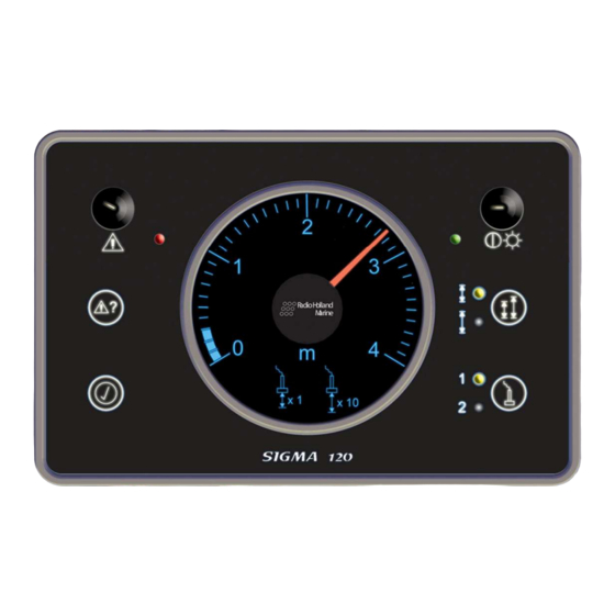
With this key, one can switch between the small range (0-4m) and the large range (0-40m). If two transducers are connected, both of them will switch- over. If SW1 is switch on, the Sigma 120 switch automatic to the right range. Selection of the transducer With this key, one can select between transducer 1 and transducer 2. - Page 30 2 seconds, all the LED’s should light up (the power supply should light up in red) and the acoustic alarm should sound until this key is released again. Version: Date: January 28, 2011 Document: Sigma 120 Rev 09 Page 30 of 60 Date 1 release: April 15, 2003...
-
Page 31: Allgemeine Beschreibung / Technische Daten
Ihrem Händler in Verbindung, wenn das nicht der Fall ist. Lesen Sie vor der Installation von dem Sigma 120 dieses Handbuch aufmerksam durch. Fragen Sie Ihren Händler, wenn Sie Fragen haben oder etwas unklar ist. - Page 32 Einbauring. 4x Feder 1.2.7 Anschlusskasten S-120 In diesem Anschlusskasten werden die erforderlichen Anschlüsse für den Tiefenmesser an dem Schwinger vorgenommen. Version: Date: January 28, 2011 Document: Sigma 120 Rev 09 Page 32 of 60 Date 1 release: April 15, 2003...
-
Page 33: Installationsvorschrift
Kabel am Schwinger darf auf keinen Fall verlängert oder verkürzt werden. Der RZ 318 darf nicht mit dem Erde verbunden werden. Lass 15 Zentimeter platz zwischen den Koaxkabel und andere Verkabelung. Version: Date: January 28, 2011 Document: Sigma 120 Rev 09 Page 33 of 60 Date 1 release: April 15, 2003... -
Page 34: Montage Schwinger
Schwinger bilden. An der Schiffshaut darf es deshalb an der Befestigungsstelle nicht zu einer Bildung von Hohlräumen kommen. Denn dadurch entsteht nämlich auch eine Störung der richtigen Funktionsweise. Version: Date: January 28, 2011 Document: Sigma 120 Rev 09 Page 34 of 60 Date 1 release: April 15, 2003... -
Page 35: Anschlüsse
Anschlüsse in dem Anschlusskasten RZ 315 an Schaltkartenmodul RZ 1958/A3 Spannungsversorgung Alarmkontakt ( nicht arbeidsam ) Verbindung zur Anzeige Rückmelder NMEA Schwinger 1 und 2 Anschlüsse Version: Date: January 28, 2011 Document: Sigma 120 Rev 09 Page 35 of 60 Date 1 release: April 15, 2003... -
Page 36: Einstellungen Für Dip-Schalter Im Modul Rz 1958/Ax
Dynamische Luftblasenunterdrückung (Euro/Delta) Ein oder zwei schwinger. Auswahl Anschlusskasten Auswahl Anschlusskasten Druckversion: EIN=A1/Höher, AUS=A0 Reserve 3.4. Einstellungen für DIP-Schalter im SIGMA 120 RZ 1965/Ax Version: Date: January 28, 2011 Document: Sigma 120 Rev 09 Page 36 of 60 Date 1... -
Page 37: Anschlüsse In Dem Anschlusskasten S-120 An Schaltkartenmodul Rz 2158/Ax
System angeschlossen ist, kann der NMEA-Eingang mit einem Falcon Sichtinstrument oder eines NMEA-Ausgang von einem MultiHUB angeschlossen werden. Die NMEA-Eingang und Ausgang sind galvanisch vom Rest der Elektronik getrennt. Version: Date: January 28, 2011 Document: Sigma 120 Rev 09 Page 37 of 60 Date 1 release: April 15, 2003... -
Page 38: Einstellungen Für Dip-Schalter Im Modul Rz 2158/A1
Description: Reserved Dynamic Air Bubble suppression OFF (Euro/Delta) Reserved JB selection JB selection Print version: ON=A1 & A2, OFF=A0 Reserved Version: Date: January 28, 2011 Document: Sigma 120 Rev 09 Page 38 of 60 Date 1 release: April 15, 2003... -
Page 39: Anschlüsse Sichtinstrument
SCREEN GND (MAIN) +24VDC (MAIN) Das Sichtinstrument des Sigma 120 kann an eine oder zwei Spannungs- versorgungen angeschlossen werden. Wir empfehlen im Hinblick auf eine bessere Betriebssicherheit das Sigma 120 an zwei Spannungsversorgungen anzuschließen. Wenn dann die Hauptspannungsversorgung mit 24 Volt ausfällt, wird das Sigma 120 mit der Reservespannungsversorgung mit 24 Volt... - Page 40 Wenn ein S-120 angeschlossen ist, wird an diesem Ausgang das Bereich ausgegeben für die S-120. K2-11 und 12: NMEA-Eingang Dieser Eingang wird bei dem Sigma 120 verwendet für anschließen des S-120. Screen Datenübertragung K3-1 und 2: Bidirektionale Datenübertragungsschnittstelle 1A K3-3 en 4: Bidirektionale Datenübertragungsschnittstelle 1B Schnittstelle 1A und 1B sind identisch (innen durchgeschaltet) An Schnittstelle 1A kann z.
-
Page 41: Bedienung
Alarmtiefe auf und ertönt ein akustisches Alarmsignal. Mit Hilfe der Taste lässt sich das akustische Alarmsignal ausschalten. Die LED für die Alarmtiefe den Alarm leuchtet weiterhin auf. Version: Date: January 28, 2011 Document: Sigma 120 Rev 09 Page 41 of 60 Date 1 release: April 15, 2003... - Page 42 LEDs aufleuchten (Versorgungsspannung muss rot aufleuchten) und wird der akustische Alarm zu hören sein, bis diese Taste wieder losgelassen wird. Version: Date: January 28, 2011 Document: Sigma 120 Rev 09 Page 42 of 60 Date 1 release: April 15, 2003...
-
Page 43: Sigma 120 Unit
SIGMA 120 unit. Version: Date: January 28, 2011 Document: Sigma 120 Rev 09 Page 43 of 60 Date 1 release: April 15, 2003... -
Page 44: Sigma 120 Frame
SIGMA 120 frame. Version: Date: January 28, 2011 Document: Sigma 120 Rev 09 Page 44 of 60 Date 1 release: April 15, 2003... -
Page 45: Sigma 120 Cut-Out Dimensions
SIGMA 120 cut-out dimensions. Version: Date: January 28, 2011 Document: Sigma 120 Rev 09 Page 45 of 60 Date 1 release: April 15, 2003... -
Page 46: Dimensions Junctionbox Rz315
DIMENSIONS JUNCTIONBOX RZ315. Version: Date: January 28, 2011 Document: Sigma 120 Rev 09 Page 46 of 60 Date 1 release: April 15, 2003... -
Page 47: Dimensions Matchingbox Rz316/Rz318 / Rz318Rev.b
57.5 mm DIMENSIONS MATCHINGBOX RZ316/RZ318 / RZ318REV.B 63.5 5.8 mm 45.5 mm Version: Date: January 28, 2011 Document: Sigma 120 Rev 09 Page 47 of 60 Date 1 release: April 15, 2003... -
Page 48: Dimensions Transducer
DIMENSIONS TRANSDUCER Version: Date: January 28, 2011 Document: Sigma 120 Rev 09 Page 48 of 60 Date 1 release: April 15, 2003... -
Page 49: Sigma 120 Ovelall Diagram
SIGMA 120 OVELALL DIAGRAM. Version: Date: January 28, 2011 Document: Sigma 120 Rev 09 Page 49 of 60 Date 1 release: April 15, 2003... -
Page 50: Sigma 120 Connections
SIGMA 120 CONNECTIONS. Rx/Tx+ Rx/Tx- Rx/Tx+ Rx/Tx- Screen Screen Version: Date: January 28, 2011 Document: Sigma 120 Rev 09 Page 50 of 60 Date 1 release: April 15, 2003... -
Page 51: Rz 315 Connections
Via RZ 318 Connection transducer 2 Via RZ 318 Connection NMEA OUT Connection repeater Connection Sigma 120 Alarm Power supply Version: Date: January 28, 2011 Document: Sigma 120 Rev 09 Page 51 of 60 Date 1 release: April 15, 2003... -
Page 52: Connections Two Rz315 On Sigma 120
Rx/Tx+ CONNECTIONS TWO RZ315 ON SIGMA 120. Rx/Tx- Rx/Tx+ Rx/Tx- K3-04 K3-03 K3-02 Rx/Tx+ K3-01 Rx/Tx- Screen K2-12 K2-11 NMEA OUT (+) K2-10 NMEA OUTPUT NMEA OUT (-) K2-09 A_OUT (+) K2-08 OUTPUT FOR A_OUT (-) ANALOG GAUGE K2-07 K2-06... -
Page 53: Connections Sigma 120 Repeater
CONNECTIONS SIGMA 120 REPEATER. K3-04 Rx/Tx+ K3-03 Rx/Tx- K3-02 Rx/Tx+ K3-01 Rx/Tx- Sc reen K2-12 K2-11 NMEA OUT (+) K2-10 NMEA OUTPUT NME A OUT (-) K2-09 A_OUT (+) K2-08 OUTP UT FOR A_OUT (-) ANALOG GAUGE K2-07 K2-06 K2-05... -
Page 54: Settings On Pcb Rz1965
SETTINGS ON PCB RZ1965. Version: Date: January 28, 2011 Document: Sigma 120 Rev 09 Page 54 of 60 Date 1 release: April 15, 2003... -
Page 55: Connection One S-120
M. connection one S-120 Version: Date: January 28, 2011 Document: Sigma 120 Rev 09 Page 55 of 60 Date 1 release: April 15, 2003... -
Page 56: Connection Two S-120
N. connection two S-120 Version: Date: January 28, 2011 Document: Sigma 120 Rev 09 Page 56 of 60 Date 1 release: April 15, 2003... -
Page 57: Intern Connection One S-120
O. intern connection one S-120 Version: Date: January 28, 2011 Document: Sigma 120 Rev 09 Page 57 of 60 Date 1 release: April 15, 2003... -
Page 58: Intern Connection Two S-120
P. intern connection two S-120 Version: Date: January 28, 2011 Document: Sigma 120 Rev 09 Page 58 of 60 Date 1 release: April 15, 2003... -
Page 59: Q Cable Connection For Sigma
Cable connection for Sigma Version: Date: January 28, 2011 Document: Sigma 120 Rev 09 Page 59 of 60 Date 1 release: April 15, 2003...
Need help?
Do you have a question about the Sigma 120 and is the answer not in the manual?
Questions and answers