Table of Contents
Advertisement
Quick Links
Radiocrafts
Embedded Wireless Solutions
TM
Tinymesh
RF Transceiver Modules
Product Description
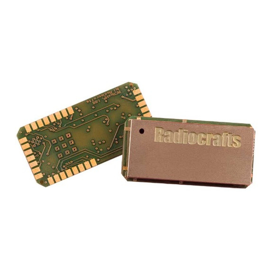
The RC11XX(HP) / RC25XX(HP) / RC17xx(HP)-TM RF Transceiver Modules are compact surface-
mounted high performance modules for wireless mesh networking applications. The modules feature a
fully embedded Tinymesh™ application and multi-hop protocol stack with automatic network forming
and self-healing features. The embedded Tinymesh™ application layer supports a full duplex UART,
Analogue- Pulse- and Digital inputs, as well as PWM and Digital outputs. Serial application data entered
on the UART port is transported automatically to the desired destination node without further interaction
from any external processor. The modules are completely shielded, available as Low Power, High
Power and Long Range Ultra Narrow Band versions, and pre-certified for operation in license free bands
from 169 MHz to 2.4 GHz.
Typical Applications
•
Wireless Sensor Networks
Automatic Meter Reading
•
Alarm- and Security Systems
•
Building Management
•
Telemetry Stations
•
Fleet Management
•
Asset Tracking
•
Street Light Control and Monitoring
•
Key Features
Embedded application layer for I/O control and data collection
•
Self-forming, self-healing and self-optimizing bi-directional mesh network stack
•
AES 128 encryption
•
•
Selectable Gateway, Router and low power End Device configuration
Configurable digital I/O, PWM (Dimmer) output and analogue inputs
•
Full Duplex Serial Port with handshake, streaming support and 256 byte buffer for easy
•
RS232/422/485 wire replacement and MODBUS RTU compatibility
Pulse counter with configurable de-bounce time and detection feedback output
•
•
'Walk-by' mode for low power data logging and metering applications
RSSI and Network connect LED output control for simplified field installation
•
Group-, Broadcast- or Individual addressing modes
•
•
Clustered Node Detection and Network Congestion Avoidance (CND/NCA™)
RF Jamming Detection and Alarm, with alarm output and network alarm messaging
•
Analogue- and Digital level triggered event messages.
•
Time-generated and event-triggered status messages
•
Locator Function for asset tracking applications
•
Network Busy Detection for ad hoc networks with multiple, roaming Gateway Devices
•
Multiple Gateway support for redundancy and automatic network load sharing
•
Small size (12.7 x 25.4 x 3.3 mm), shielded and optimized for SMD mounting
•
No external components
•
Wide supply voltage range
•
RC1x40/80(HP)-TM conforms with EU R&TTE directive (EN 300 220, EN 301 489, EN 60950)
•
•
RC119x-TM conforms with regulations for operation under FCC CFR 47 part 15
RC117x(HP)-TM complies with G.S.R.564(E) (G.S.R.168(E)).
•
•
RC2500(HP)-TM complies with EN 300 328 (Europe), FCC CFR 47 part 15 (US) and ARIB STD-
T66 (Japan)
RC117x-TM and RC117xHP-TM comply to IEEE 802.15.4.g PHY mode 0 encoding when
•
configured for RF Data Rate 8.
©2016 Radiocrafts AS
RC11xx(HP)/25xx(HP)/17xx(HP)-TM Data Sheet rev. 1.48
©2016 Tiny Mesh AS
RC11xx(HP)-TM
RC25xx(HP)-TM
RC17xx(HP)-TM
Page 1 of 86
Advertisement
Table of Contents

Related Manuals for Radiocrafts Tinymesh RC11 -TM Series


Summary of Contents for Radiocrafts Tinymesh RC11 -TM Series
-
Page 1: Product Description
RC2500(HP)-TM complies with EN 300 328 (Europe), FCC CFR 47 part 15 (US) and ARIB STD- T66 (Japan) RC117x-TM and RC117xHP-TM comply to IEEE 802.15.4.g PHY mode 0 encoding when • configured for RF Data Rate 8. ©2016 Radiocrafts AS RC11xx(HP)/25xx(HP)/17xx(HP)-TM Data Sheet rev. 1.48 Page 1 of 86 ©2016 Tiny Mesh AS... -
Page 2: Quick Reference Data
Please see additional schematic information regarding recommended Reset and Power supply filtering, LED outputs, configurable I/O pins and how to include a firmware upgrade connector later in this document. Radiocrafts will deliver RC11x0-TM or RC11x1-TM and RC11x0HP-TM or RC11x1HP-TM depending on availability. The versions performance is identical. ©2016 Radiocrafts AS RC11xx(HP)/25xx(HP)/17xx(HP)-TM Data Sheet rev. -
Page 3: Table Of Contents
Router in Packet Mode Transmitting Command and Configuration Packets from Gateway Group and Broadcast Addressing Command Acknowledge Command Packet Format Transmit Serial Data Packet from Gateway ©2016 Radiocrafts AS RC11xx(HP)/25xx(HP)/17xx(HP)-TM Data Sheet rev. 1.48 Page 3 of 86 ©2016 Tiny Mesh AS... - Page 4 Packet Mode Demo: Digital Output Control, PWM Dimming and Input Trigger End Device Test and Demo, Pulse Counter with Feedback Antenna Connection PCB Layout Recommendations Mechanical Drawing Mechanical Dimensions ©2016 Radiocrafts AS RC11xx(HP)/25xx(HP)/17xx(HP)-TM Data Sheet rev. 1.48 Page 4 of 86 ©2016 Tiny Mesh AS...
- Page 5 Regulatory Compliance Disclaimer Typical Application Circuit Power Supply Appendix: ASCII Table Document Revision History Product Status and Definitions Disclaimer Trademarks Life Support Policy Contact Information ©2016 Radiocrafts AS RC11xx(HP)/25xx(HP)/17xx(HP)-TM Data Sheet rev. 1.48 Page 5 of 86 ©2016 Tiny Mesh AS...
-
Page 6: Tinymesh™ Application And Protocol Stack
Router Devices are full-functioning devices with serial data UART and Input / Output capabilities. Router Devices provide the communication path between individual Router- or End-devices, and the network ©2016 Radiocrafts AS RC11xx(HP)/25xx(HP)/17xx(HP)-TM Data Sheet rev. 1.48 Page 6 of 86... -
Page 7: End Device
Data received by the device, and event data generated by the device will be stored in the internal device buffers until a valid connection has been established. ©2016 Radiocrafts AS RC11xx(HP)/25xx(HP)/17xx(HP)-TM Data Sheet rev. 1.48 Page 7 of 86... -
Page 8: Self-Optimizing
Gateway is powered up. Depending on the device configuration, the Gateway device will either refuse connection, provide an alert, or ignore the ©2016 Radiocrafts AS RC11xx(HP)/25xx(HP)/17xx(HP)-TM Data Sheet rev. 1.48 Page 8 of 86 ©2016 Tiny Mesh AS... -
Page 9: Alerts And Device Triggered Events
A special two-step mechanism protects the most sensitive configuration parameters that may cause a device to lose network connection. ©2016 Radiocrafts AS RC11xx(HP)/25xx(HP)/17xx(HP)-TM Data Sheet rev. 1.48 Page 9 of 86 ©2016 Tiny Mesh AS... -
Page 10: Getting Started
Router(s). Data entered at any Router Device (while CTS is low), will be delivered to the Gateway and presented on the Gateway TXD pin. ©2016 Radiocrafts AS RC11xx(HP)/25xx(HP)/17xx(HP)-TM Data Sheet rev. 1.48 Page 10 of 86 ©2016 Tiny Mesh AS... -
Page 11: What About The Antenna
In most cases, a simple quarter wavelength wire or a PCB track will do. Connect a piece of wire to the RF pin with length corresponding to the quarter of a wavelength. When space is limited, contact Radiocrafts for recommendations for the best antenna solution for your application. How do I change the RF Channel or any other Parameter? Configurable parameters such as RF Channel, RF Power or RF Data Rate, are stored in non-volatile memory in the module. -
Page 12: Module Pin Assignment
For UART communication, the TXD and RXD are used for serial data, and CTS for flow control. RXD must be high when not sending data to the module. ©2016 Radiocrafts AS RC11xx(HP)/25xx(HP)/17xx(HP)-TM Data Sheet rev. 1.48 Page 12 of 86... - Page 13 Flash pattern given for current sourcing: Flash frequency indicates network connection redundancy for Routers and End Devices. Flash indicates RF RX (received packets) for Gateway Devices ©2016 Radiocrafts AS RC11xx(HP)/25xx(HP)/17xx(HP)-TM Data Sheet rev. 1.48 Page 13 of 86 ©2016 Tiny Mesh AS...
-
Page 14: Pin Description, 17Xx Unb Devices
For UART communication, the TXD and RXD are used for serial data, and CTS for flow control. RXD must be high when not sending data to the module. ©2016 Radiocrafts AS RC11xx(HP)/25xx(HP)/17xx(HP)-TM Data Sheet rev. 1.48 Page 14 of 86... - Page 15 +27 dBm at 3.3 V. 23,24, RESERVED Test pins or pins reserved for future 25,27, use. Do not connect! 28,31, 32,33, 34,35, 36,37, 38,39, 40,42 ©2016 Radiocrafts AS RC11xx(HP)/25xx(HP)/17xx(HP)-TM Data Sheet rev. 1.48 Page 15 of 86 ©2016 Tiny Mesh AS...
-
Page 16: Circuit Description
Ultra Narrow Band version. As new members are added to the Radiocrafts family of modules, the Tinymesh™ Stack will be introduced on the new platforms. -
Page 17: Rctools
RCTools is a powerful and easy to use PC suite that helps you during test, development and deployment of the RC11XX(HP) / 25XX(HP)-TM. The tools may be used for both configuration and communication testing. Visit www.radiocrafts.com for a free download and full documentation. ©2016 Radiocrafts AS RC11xx(HP)/25xx(HP)/17xx(HP)-TM Data Sheet rev. -
Page 18: Transparent Mode Operation
Serial data entered and received at the Gateway will contain extra bytes for addressing, command and control. ©2016 Radiocrafts AS RC11xx(HP)/25xx(HP)/17xx(HP)-TM Data Sheet rev. 1.48 Page 18 of 86 ©2016 Tiny Mesh AS... -
Page 19: Transparent- And Packet Mode Functions
Router The RXTX mode is provided for direction control of RS485 drivers. When RXTX is enabled, the module UART will set CTS HIGH during data ©2016 Radiocrafts AS RC11xx(HP)/25xx(HP)/17xx(HP)-TM Data Sheet rev. 1.48 Page 19 of 86 ©2016 Tiny Mesh AS... -
Page 20: Aes Encryption
An encrypted Gateway will accept and decrypt messages from encrypted nodes, as well as accept data packets from unencrypted nodes. An un-encrypted Gateway will only accept messages from un-encrypted nodes. • ©2016 Radiocrafts AS RC11xx(HP)/25xx(HP)/17xx(HP)-TM Data Sheet rev. 1.48 Page 20 of 86 ©2016 Tiny Mesh AS... -
Page 21: Sleep Mode
DATA MSB will indicate the duration of the jamming situation in minutes, and the MESSAGE DATA LSB will indicate the time since the jamming condition ended in hours. ©2016 Radiocrafts AS RC11xx(HP)/25xx(HP)/17xx(HP)-TM Data Sheet rev. 1.48 Page 21 of 86... -
Page 22: Clustered Node Detection And Network Congestion Avoidance (Cnd/Nca™)
For further information, please reference the later chapter on AUTOMATIC STATUS REPORTING. ©2016 Radiocrafts AS RC11xx(HP)/25xx(HP)/17xx(HP)-TM Data Sheet rev. 1.48 Page 22 of 86... -
Page 23: Led Indicators
Module pins RSSI/ TX LED and CONNECTION/ RX LED are designed to directly drive LEDs. The Red LED (D1) of the Radiocrafts Demo Board is connected to module pin RSSI/ TX LED, and the Yellow LED (D2) is connected to module pin CONNECTION/ RX LED. -
Page 24: Radio Rx /Tx Indicator Led
The device connection status may be included in the data field of STATUS MESSAGE (IMA) messages Radio RX /TX Indicator LED When configured as a Gateway Device, an LED connected to module pin RSSI/ TX LED (Radiocrafts Demo Board Red LED), will flash every time an RF packet is transmitted. An LED connected to module pin CONNECTION/ RX LED (Radiocrafts Demo Board Yellow LED), will flash every time an RF packet with valid formatting and valid CRC is received. -
Page 25: Packet Mode Operation
UNIQUE_ID in the command NODE ADDRESS is interpreted as a group identifier by the receiving device. The addressing structure for group commands is '255 255 255 nnn', where the 'nnn' byte represents the ©2016 Radiocrafts AS RC11xx(HP)/25xx(HP)/17xx(HP)-TM Data Sheet rev. 1.48 Page 25 of 86... -
Page 26: Command Acknowledge
. Byte = address For other Command arguments, this byte is . Byte= value don't care. ….. Introduced with Tinymesh™ release 1.40 Introduced with Tinymesh™ release 1.43 ©2016 Radiocrafts AS RC11xx(HP)/25xx(HP)/17xx(HP)-TM Data Sheet rev. 1.48 Page 26 of 86 ©2016 Tiny Mesh AS... -
Page 27: Transmit Serial Data Packet From Gateway
Packet Type Event 2 (0x02) or Serial data in 16 (0x10) General Event Packet Format (Packet Type 0x02) Byte # Field name Size Description ©2016 Radiocrafts AS RC11xx(HP)/25xx(HP)/17xx(HP)-TM Data Sheet rev. 1.48 Page 27 of 86 ©2016 Tiny Mesh AS... - Page 28 16,17 User selected command number Address(ID) Data Message Detail Message Data ACK and NAK messages from Gateway Device truncated after the Message Data Fields ©2016 Radiocrafts AS RC11xx(HP)/25xx(HP)/17xx(HP)-TM Data Sheet rev. 1.48 Page 28 of 86 ©2016 Tiny Mesh AS...
- Page 29 Single data block, terminated by UART time-out. 1-255: Block (partition) number in large data streams controlled by CTS or Xon/Xoff handshake Serial data 1..120 Serial data ©2016 Radiocrafts AS RC11xx(HP)/25xx(HP)/17xx(HP)-TM Data Sheet rev. 1.48 Page 29 of 86 ©2016 Tiny Mesh AS...
-
Page 30: Practical Use Of Packet Header Data
MESSAGE DATA MSB, MESSAGE DATA LSB and ADDRESS(ID) DATA packet fields is configurable through the IMA MESSAGE DATA FIELD CONTENTS and the IMA MESSAGE ADDRESS FIELD CONTENTS parameters. ©2016 Radiocrafts AS RC11xx(HP)/25xx(HP)/17xx(HP)-TM Data Sheet rev. 1.48 Page 30 of 86... -
Page 31: Serial Data Block Counter
In some applications using ad hoc networks with, for instance, portable Gateway Devices, it may be important for the operation of the systems that only one Gateway Device is active at any time. ©2016 Radiocrafts AS RC11xx(HP)/25xx(HP)/17xx(HP)-TM Data Sheet rev. 1.48 Page 31 of 86 ©2016 Tiny Mesh AS... -
Page 32: Network Id
Event messages triggered by input status changes will be transmitted immediately, providing a more responsive approach than what may be achieved in a traditional, polled system. Please reference the chapters ©2016 Radiocrafts AS RC11xx(HP)/25xx(HP)/17xx(HP)-TM Data Sheet rev. 1.48 Page 32 of 86... -
Page 33: Receive Neighbour Function
GPIO. The receiving application may interpret this signal as a command to turn on/ off a function, such as a light source. ©2016 Radiocrafts AS RC11xx(HP)/25xx(HP)/17xx(HP)-TM Data Sheet rev. 1.48 Page 33 of 86... -
Page 34: Input / Output Functions
The counter status may be viewed either in a two-byte format, by selecting the IMA MESSAGE DATA FIELD CONTENTS parameter = 2, or in a four byte format, by setting IMA MESSAGE ADDRESS FIELD CONTENTS ©2016 Radiocrafts AS RC11xx(HP)/25xx(HP)/17xx(HP)-TM Data Sheet rev. 1.48 Page 34 of 86... -
Page 35: Pulse Counter De-Bounce
INDICATORS ON Note: Duration of the Pulse Counter Feedback Indicator function is controlled by the parameter. Pulse Counter Feedback will terminate when Indicators are off. ©2016 Radiocrafts AS RC11xx(HP)/25xx(HP)/17xx(HP)-TM Data Sheet rev. 1.48 Page 35 of 86 ©2016 Tiny Mesh AS... -
Page 36: Digital Output Control
Change Change Change Change Change Change GPIO mapping GPIO7 GPIO6 GPIO5 GPIO4 GPIO3 GPIO2 GPIO1 GPIO0 Module Module Module Module Module Module Module Module ©2016 Radiocrafts AS RC11xx(HP)/25xx(HP)/17xx(HP)-TM Data Sheet rev. 1.48 Page 36 of 86 ©2016 Tiny Mesh AS... -
Page 37: Digital Output Drive
1228*1.25 / 2047= 0.75 [V] Please note that negative voltages or voltages above the module supply voltage may result in permanent damage to the module, please reference the electrical specifications for details. ©2016 Radiocrafts AS RC11xx(HP)/25xx(HP)/17xx(HP)-TM Data Sheet rev. 1.48 Page 37 of 86... -
Page 38: Analogue Input Event Triggering
The sliding average and the sampling interval may be used as a filter function to eliminate spurious glitches in the measured voltage. The default sampling interval is set for 1 second. ©2016 Radiocrafts AS RC11xx(HP)/25xx(HP)/17xx(HP)-TM Data Sheet rev. 1.48 Page 38 of 86... -
Page 39: End Device
On wakeup from the pulse counter, the module will not dispatch data, but return directly to sleep mode after detecting the pulse. ©2016 Radiocrafts AS RC11xx(HP)/25xx(HP)/17xx(HP)-TM Data Sheet rev. 1.48 Page 39 of 86 ©2016 Tiny Mesh AS... -
Page 40: Wake Up From Digital Input
The determining factor is going to be how often the module is awake, for how long time, and what is the power consumption of the module plus interfacing circuits while the module is awake. Number of instances Module type ©2016 Radiocrafts AS RC11xx(HP)/25xx(HP)/17xx(HP)-TM Data Sheet rev. 1.48 Page 40 of 86 ©2016 Tiny Mesh AS... -
Page 41: Analogue Port Sampling By End Devices
The STATUS MESSAGE (IMA) event message contains current status of all digital- and analogue inputs, module temperature and module voltage level, as well as the current status of the pulse counter, either in 2- or 4-byte format. ©2016 Radiocrafts AS RC11xx(HP)/25xx(HP)/17xx(HP)-TM Data Sheet rev. 1.48 Page 41 of 86... -
Page 42: Receive And Transmit Timing
Time to transmit ACK packet, including preamble and sync TX(ACK) Note: Timing diagram representative for packet transmission without collision and retry, and no wait for clear channel delay. ©2016 Radiocrafts AS RC11xx(HP)/25xx(HP)/17xx(HP)-TM Data Sheet rev. 1.48 Page 42 of 86 ©2016 Tiny Mesh AS... -
Page 43: Uart Receive And Cts Timing
(10 x 0.521) + 10 + 2 + 5.3 + 2 + 5.3 + 10 = 39.8 ms max: (10 x 0.521) + 10 + 32 + 5.3 + 32 + 5.3 + 10= 99.8 ms ©2016 Radiocrafts AS RC11xx(HP)/25xx(HP)/17xx(HP)-TM Data Sheet rev. 1.48 Page 43 of 86 ©2016 Tiny Mesh AS... -
Page 44: Memory Configuration Timing
Time from end of command byte to start of response byte received on UART on Command-Response all commands except R, G, N and memory configuration commands. 1 ms Time from 'X' command until module in normal operation CONFIG-IDLE ©2016 Radiocrafts AS RC11xx(HP)/25xx(HP)/17xx(HP)-TM Data Sheet rev. 1.48 Page 44 of 86 ©2016 Tiny Mesh AS... -
Page 45: Rf Frequencies, Output Power And Data Rates
For channels 17 and 18, the maximum RF speed is 1.2 kbit/s and maximum output power is +25 dBm, due to limitations in spectrum spread at the 869.4-869.65 MHz band-edges. 76.8 kbit/s is maximum RF bitrate for HP version. 100 kbit/s setting not available ©2016 Radiocrafts AS RC11xx(HP)/25xx(HP)/17xx(HP)-TM Data Sheet rev. 1.48 Page 45 of 86... - Page 46 7: For future use 4: 2403.75 MHz 1: -10 dBm 8: 50kbit/s 0 dBm 5 dBm 10 dBm 5: 17 dBm Available from firmware release 1.45 ©2016 Radiocrafts AS RC11xx(HP)/25xx(HP)/17xx(HP)-TM Data Sheet rev. 1.48 Page 46 of 86 ©2016 Tiny Mesh AS...
- Page 47 * 0.0125 MHz n = channel [153, 173] RF Channel, Output Power and Data Rate must be set identical for all devices within a network. ©2016 Radiocrafts AS RC11xx(HP)/25xx(HP)/17xx(HP)-TM Data Sheet rev. 1.48 Page 47 of 86 ©2016 Tiny Mesh AS...
- Page 48 For more details on changing the RF channel, output power or data rate, refer to the description of the CONFIGURATION COMMANDS. Available on request, MOQ applies ©2016 Radiocrafts AS RC11xx(HP)/25xx(HP)/17xx(HP)-TM Data Sheet rev. 1.48 Page 48 of 86 ©2016 Tiny Mesh AS...
- Page 49 RC118x-TM, channels 5-9 are license free channels within Russia. RC119x-TM is pending approval under FCC for use in the US and Canada. For more information see section REGULATORY COMPLIANCE INFORMATION. ©2016 Radiocrafts AS RC11xx(HP)/25xx(HP)/17xx(HP)-TM Data Sheet rev. 1.48 Page 49 of 86...
-
Page 50: Module Configuration
No Response Restores configuration memory to (0x40 0x54 factory default values. 0x4D) Exit ‘X’ (0x58) No argument No Response Exit to normal operation mode. All ©2016 Radiocrafts AS RC11xx(HP)/25xx(HP)/17xx(HP)-TM Data Sheet rev. 1.48 Page 50 of 86 ©2016 Tiny Mesh AS... -
Page 51: Rssi Reading (S- Command)
©2016 Radiocrafts AS RC11xx(HP)/25xx(HP)/17xx(HP)-TM Data Sheet rev. 1.48 Page 51 of 86... -
Page 52: Temperature Reading (U- Command)
The Module remains in Configuration Mode until 'X' command received 0x58 No response The Tinymesh protocol runs through a full Power On Reset Cycle, to ensure all configuration changes are applied. ©2016 Radiocrafts AS RC11xx(HP)/25xx(HP)/17xx(HP)-TM Data Sheet rev. 1.48 Page 52 of 86 ©2016 Tiny Mesh AS... -
Page 53: Set Sleep Mode (Z-Command)
The internal temperature sensor may require calibration to show correct value. The TEMP OFFSET parameter in CALIBRATION MEMORY is used for temperature calibration in steps of 0.25 degree Celsius. ©2016 Radiocrafts AS RC11xx(HP)/25xx(HP)/17xx(HP)-TM Data Sheet rev. 1.48 Page 53 of 86... -
Page 54: Setting And Changing The Network Id (Nid)
By Asserting and releasing the input, or Mode By issuing the SET GATEWAY IN CONFIG MODE command to a Gateway Device 'HW' 0x48 '>' Wait for '>' prompt ©2016 Radiocrafts AS RC11xx(HP)/25xx(HP)/17xx(HP)-TM Data Sheet rev. 1.48 Page 54 of 86 ©2016 Tiny Mesh AS... -
Page 55: Setting And Changing The Fixed Destination Id (Fdid)
Tinymesh™ packet, followed by a limited set of descriptive data derived from the received packet. Only packets with matching SYSTEM_ID will be accepted by the Sniffer function. ©2016 Radiocrafts AS RC11xx(HP)/25xx(HP)/17xx(HP)-TM Data Sheet rev. 1.48 Page 55 of 86... - Page 56 To avoid losing data, the transfer speed should be set to the highest acceptable data rate. The UART BAUD RATE Tinymesh™ module will support data rates up to 230 400 by setting the parameter in Configuration Memory. ©2016 Radiocrafts AS RC11xx(HP)/25xx(HP)/17xx(HP)-TM Data Sheet rev. 1.48 Page 56 of 86 ©2016 Tiny Mesh AS...
-
Page 57: Configuration Memory
Default value 0 or 255 provides auto setting per configured RF DATA RATE from FW 1.44 Changed to 140 from FW version 1.44 Set by ‘G’, ‘R’, 'N'-command in Configuration Mode Zero value treated as 1 ©2016 Radiocrafts AS RC11xx(HP)/25xx(HP)/17xx(HP)-TM Data Sheet rev. 1.48 Page 57 of 86 ©2016 Tiny Mesh AS... - Page 58 Applies to End Device selection Values out of range will be treated as 1 (Input) Values out of range will be treated as 0 (No Trig) ©2016 Radiocrafts AS RC11xx(HP)/25xx(HP)/17xx(HP)-TM Data Sheet rev. 1.48 Page 58 of 86 ©2016 Tiny Mesh AS...
- Page 59 Value different from 9 will be treated as 8 Value different from 1 will be treated as zero (no parity) Value different from 2 will be treated as 1 (Single stop bit) ©2016 Radiocrafts AS RC11xx(HP)/25xx(HP)/17xx(HP)-TM Data Sheet rev. 1.48 Page 59 of 86...
- Page 60 RTS, Xon/ Xoff, ACK/NAK, Wait For ACK from FW 1.31. RXTX from FW 1.40 Unrecognised values will be treated as 1 (Encrypted) Value different from 0 will be treated as 1 (on) ©2016 Radiocrafts AS RC11xx(HP)/25xx(HP)/17xx(HP)-TM Data Sheet rev. 1.48 Page 60 of 86...
- Page 61 Value larger than 2 will be treated as 2 Out of range values will be treated as Disabled Available for special version firmware only ©2016 Radiocrafts AS RC11xx(HP)/25xx(HP)/17xx(HP)-TM Data Sheet rev. 1.48 Page 61 of 86 ©2016 Tiny Mesh AS...
- Page 62 Reset Configuration memory to backup Reserved Changed from 0x3F to 0x1F in FW release 1.42 applicable Not applicable from fw version 1.46 ©2016 Radiocrafts AS RC11xx(HP)/25xx(HP)/17xx(HP)-TM Data Sheet rev. 1.48 Page 62 of 86 ©2016 Tiny Mesh AS...
-
Page 63: Calibration Memory
Note: Address locations not listed, should not be changed from their default values Default value changed from 5 to 0 starting with Tiymesh version 1.42 ©2016 Radiocrafts AS RC11xx(HP)/25xx(HP)/17xx(HP)-TM Data Sheet rev. 1.48 Page 63 of 86... -
Page 64: Demo Board Exercises
RC11xx(HP)-TM RC25xx(HP)-TM Embedded Wireless Solutions RC17xx(HP)-TM Demo Board Exercises With Radiocrafts TM-CCT examples Hardware required: Minimum two demo boards Preparation: Connect serial ports to computer USB ports. Open a copy of TM-CCT for each of the connected demo boards. Select appropriate COM: port at 19200 bps, click the Connect button for each demo board. -
Page 65: Packet Mode Serial Communication, Test And Demo
Serial Data packet received by Gateway Device: Enter text string in clear text, then click Text String: Hi Meshy Serial Data Packet SERIAL DATA MESSSAGE ©2016 Radiocrafts AS RC11xx(HP)/25xx(HP)/17xx(HP)-TM Data Sheet rev. 1.48 Page 65 of 86 ©2016 Tiny Mesh AS... -
Page 66: Packet Mode Demo: Digital Output Control, Pwm Dimming And Input Trigger
GPIO 0 LED = Off (Output is Low) Paste the Command String to TM-CCT, click Observe response message from Router Device: Length of received packet: 0x23 = 35d ©2016 Radiocrafts AS RC11xx(HP)/25xx(HP)/17xx(HP)-TM Data Sheet rev. 1.48 Page 66 of 86 ©2016 Tiny Mesh AS... - Page 67 Using a digital input to trigger an alarm message Observe: Trig GPIO 4 Message received from Router Device: Press S7 button Input Change Detected Triggered by GPIO 4 DIGITAL INPUT CHANGE DETECTED ©2016 Radiocrafts AS RC11xx(HP)/25xx(HP)/17xx(HP)-TM Data Sheet rev. 1.48 Page 67 of 86 ©2016 Tiny Mesh AS...
-
Page 68: End Device Test And Demo, Pulse Counter With Feedback
Press S7 button to simulate pulse input Observe: Counter status Short flash on Pulse Counter Feedback LED, No glitches on pressing and releasing switch STATUS MESSAGE (IMA) ©2016 Radiocrafts AS RC11xx(HP)/25xx(HP)/17xx(HP)-TM Data Sheet rev. 1.48 Page 68 of 86 ©2016 Tiny Mesh AS... -
Page 69: Antenna Connection
50 ohms. The lengths of a quarter-wave antenna for different operational frequencies are given in the table below. Frequency Length [MHz] [cm] 16.4 865-867 2450 ©2016 Radiocrafts AS RC11xx(HP)/25xx(HP)/17xx(HP)-TM Data Sheet rev. 1.48 Page 69 of 86 ©2016 Tiny Mesh AS... -
Page 70: Pcb Layout Recommendations
It is recommended that vias be tented. Reserved pins should be soldered to the pads but the pads must be left floating. Note that Radiocrafts technical support team is available for schematic and layout review of your design. ©2016 Radiocrafts AS RC11xx(HP)/25xx(HP)/17xx(HP)-TM Data Sheet rev. -
Page 71: Mechanical Drawing
Ultrasonic processes like ultrasonic cleaning and ultrasonic welding to assemble plastic enclosures can cause deterioration or destruction of components inside the module. Please avoid ultrasonic processes on products that include any of the RC11xxHP module variants in the design. ©2016 Radiocrafts AS RC11xx(HP)/25xx(HP)/17xx(HP)-TM Data Sheet rev. 1.48 Page 71 of 86... -
Page 72: Absolute Maximum Ratings
When the module operates in IDLE/RX/TX, the loaded battery voltage will usually drop to fall inside the module operating voltage range as referenced in table ©2016 Radiocrafts AS RC11xx(HP)/25xx(HP)/17xx(HP)-TM Data Sheet rev. 1.48 Page 72 of 86... - Page 73 Note: RC11xxHP-TM and RC2500HP-TM have absolute maximum ratings close to the nominal output of a 3.6V Li Cell, and must not be connected directly to a battery without introducing a voltage drop between the module and the battery. ©2016 Radiocrafts AS RC11xx(HP)/25xx(HP)/17xx(HP)-TM Data Sheet rev. 1.48 Page 73 of 86...
-
Page 74: Electrical Specifications
EN300-220-2 V2.4.1. The 25 kHz narrow band ACP requirement will limit the output power to +22 dBm when characterised as 25 kHz channel under EN300-220-2. For 12.5 kHz narrow band systems the RC17x0HP-TM complies with ACP up to +27 dBm. ©2016 Radiocrafts AS RC11xx(HP)/25xx(HP)/17xx(HP)-TM Data Sheet rev. 1.48 Page 74 of 86... - Page 75 -109 -110 50 kbit/s -106 -107 100 kbit/s -101 -102 Adjacent channel rejection RC11xx – 25xx-TM RC11xxHP-TM, 25xxHP-TM RC17xxHP-TM Alternate channel selectivity RC11xx(HP)/25xx(HP)-TM RC17XX(HP)-TM ©2016 Radiocrafts AS RC11xx(HP)/25xx(HP)/17xx(HP)-TM Data Sheet rev. 1.48 Page 75 of 86 ©2016 Tiny Mesh AS...
- Page 76 RC2500-TM RC2500HP-TM RC17xx-TM RC17xxHP-TM VCC_PA RC1701HP-TM VCC_PA Current consumption, RX/IDLE Apply over entire supply voltage RC114x–RC119x-TM (LP&HP) range RC2500-TM RC2500HP-TM RC17xx(HP)-TM VCC_PA 3 *10 ©2016 Radiocrafts AS RC11xx(HP)/25xx(HP)/17xx(HP)-TM Data Sheet rev. 1.48 Page 76 of 86 ©2016 Tiny Mesh AS...
- Page 77 Output logic level, low (1µA) Output logic level,high(-1µA) SET pin Minimum 250 ns pulse width Input logic level, low 30 % Input logic level, high 70 % ©2016 Radiocrafts AS RC11xx(HP)/25xx(HP)/17xx(HP)-TM Data Sheet rev. 1.48 Page 77 of 86 ©2016 Tiny Mesh AS...
- Page 78 The guaranteed number of write cycles cycles using the ‘M’ command is limited PWM switching frequency Applies to GPIO 7 when configured for PWM ©2016 Radiocrafts AS RC11xx(HP)/25xx(HP)/17xx(HP)-TM Data Sheet rev. 1.48 Page 78 of 86 ©2016 Tiny Mesh AS...
-
Page 79: Regulatory Compliance Information
R&TTE directive (EU) According to R&TTE directives, it is the responsibility of Radiocrafts customers to check that the host product (i.e. final product) is compliant with R&TTE essential requirements. The use of a CE marked radio module can avoid re-certification of the final product, provided that the end user respects the recommendations established by Radiocrafts. -
Page 80: Wpc Compliance (India)
Users must assess and verify that their final product meets the appropriate specifications and to perform the required procedures for regulatory compliance. The relevant regulations are subject to change. Radiocrafts AS does not take responsibility for the validity and accuracy of the understanding of the regulations referred above. Radiocrafts only guarantee that this product meets the specifications in this document. -
Page 81: Typical Application Circuit
For recommended connection of CONFIG, RESET and UART pins, please see table below • Application Circuit No MCU, No Serial Port No MCU, with Serial Port MCU with serial port ©2016 Radiocrafts AS RC11xx(HP)/25xx(HP)/17xx(HP)-TM Data Sheet rev. 1.48 Page 81 of 86 ©2016 Tiny Mesh AS... - Page 82 Apply Pull Up (R2) to VCC Apply Pull Up (R2) to unless driven by a push-pull VCC unless driven by a output push-pull output ©2016 Radiocrafts AS RC11xx(HP)/25xx(HP)/17xx(HP)-TM Data Sheet rev. 1.48 Page 82 of 86 ©2016 Tiny Mesh AS...
-
Page 83: Power Supply
Component Manufacturer Part number EMI filter bead Murata BLM11A102S, ordering code BLM18xx102xN1D For High Power versions of modules use BLM18SG331TN1 ©2016 Radiocrafts AS RC11xx(HP)/25xx(HP)/17xx(HP)-TM Data Sheet rev. 1.48 Page 83 of 86 ©2016 Tiny Mesh AS... -
Page 84: Appendix: Ascii Table
Radiocrafts RC11xx(HP)-TM RC25xx(HP)-TM Embedded Wireless Solutions RC17xx(HP)-TM Appendix: ASCII Table CTRL " & − − − − < > ©2016 Radiocrafts AS RC11xx(HP)/25xx(HP)/17xx(HP)-TM Data Sheet rev. 1.48 Page 84 of 86 ©2016 Tiny Mesh AS... -
Page 85: Document Revision History
Radiocrafts. The data sheet is printed for reference information only. Disclaimer Radiocrafts AS believes the information contained herein is correct and accurate at the time of this printing. However, Radiocrafts AS reserves the right to make changes to this product without notice. ©2016 Radiocrafts AS RC11xx(HP)/25xx(HP)/17xx(HP)-TM Data Sheet rev. -
Page 86: Trademarks
Radiocrafts AS customers using or selling these products for use in such applications do so at their own risk and agree to fully indemnify Radiocrafts AS for any damages resulting from any improper use or sale.
Need help?
Do you have a question about the Tinymesh RC11 -TM Series and is the answer not in the manual?
Questions and answers