Table of Contents
Advertisement
Available languages
Available languages
Quick Links
E
KIT 12V PARA CANCELAS BATIENTES CON HOJAS DE HASTA 2 m
P
KIT 12V PARA PORTÕES A BATENTE COM FOLHAS ATÉ 2 m DE COMPRIMENTO
12V KIT FOR SWING GATES UP TO 2 m LEAF
GB
F
KIT POUR PORTAILS À VANTAIL JUSQU' À 2 m DE LONGUEUR
D
BAUSATZ FÜR GITTERTÜRE, DIE TÜRFLÜGEL MIT EINER MAXIMALER LÄNGE VON 2 m HABEN
DIMOEL
www.dimoel.es
info@dimoel.es
IL n. 145-A
EDIZ. 05/04/04
KIT BATT12V
Advertisement
Chapters
Table of Contents

Related Manuals for DIMOEL KIT BATT12V


Summary of Contents for DIMOEL KIT BATT12V
- Page 1 IL n. 145-A EDIZ. 05/04/04 KIT BATT12V KIT 12V PARA CANCELAS BATIENTES CON HOJAS DE HASTA 2 m KIT 12V PARA PORTÕES A BATENTE COM FOLHAS ATÉ 2 m DE COMPRIMENTO 12V KIT FOR SWING GATES UP TO 2 m LEAF KIT POUR PORTAILS À...
- Page 2 KIT BATT12V INSTRUCCIONES ..........1 INSTRUÇÕES .
-
Page 3: Table Of Contents
ÍNDICE ADVERTENCIAS IMPORTANTES ..........2 CONFORMIDAD A LAS NORMATIVAS . -
Page 4: Advertencias Importantes
ADVERTENCIAS IMPORTANTES CONFORMIDAD A LAS NORMATIVAS DIMOEL S.L. declara que los componentes del kit son La DIMOEL S.L. se reserva el derecho de aportar conformes con los requisitos esenciales fijados por las eventuales modificaciones al producto sin previo aviso; Directivas: ademmás, no se hace responsable de danos a personas... -
Page 5: Lista De Componentes
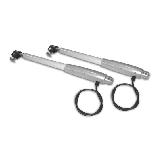
LISTA DE COMPONENTES Ref. Descripción Cant. Operadores electromecánicos 12VDC Cuadro de maniobras PRG12PP Emisores TRC-4 DM Lámpara de señalización EGG12 Soporte para instalación operadores al poste 2 Perno para instalación operador Seeger para sujetar perno Soporte para instalación operadores a la hoja 2 Pinza tubular Arandelas de plástico Arandelas de plástico de reserva... -
Page 6: Datos Técnicos Slim12V
DATOS TÉCNICOS SLIM12V Longitud máxima de la hoja Alimentación 12 VDC Potencia motor 30 W Carrera máx. de arrastre 300 mm Velocidad de arrastre 0,016 m/s Temperatura de funcionamiento -20 ÷ +60 °C Grado de protección IP44 Ciclo de trabajo 80 % Peso motor 3 Kg... -
Page 7: Montaje De Los Operadores
MONTAJE DE LOS OPERADORES Para instalar de forma correcta los operadores a la puerta seguir atentamente los siguientes puntos: • Marcar en los postes las medidas A y B que se consideren más oportunas. • Instalar los soportes 5 a los postes y posicionar los operadores en ellos. -
Page 8: Esquema De Instalación
ESQUEMA DE INSTALACIÓN INSTALACION DEL CUADRO DE INSTALACION DE LAS FOTOCELULAS MANIOBRAS Esta operación debe efectuarse únicamente siguiendo las instrucciones del constructor. La posición de monta- Es importante instalar el cuadro de maniobras lo más je ideal prevé que el eje óptico entre el receptor y el cerca posible de la puerta para evitar utilizar cables de emisor quede a una altura incluida entre 30 y 60 cm conexión excesivamente largos. -
Page 9: Descripcion Del Cuadro De Maniobras
DESCRIPCION DEL CUADRO DE CONEXION DE LOS BORNES MANIOBRAS 1 - 4 Conectar al pulsador/es de START El PRG12PP ha sido desarrollado para el comando de (contacto normalmente abierto o cancelas de una o dos hojas, motorizadas con operadores en corriente continua a 12 Voltios. normalmente cerrado seleccionable Las ventajas derivadas por uso de sistemas de auto- en programación con switch 5). -
Page 10: Instalacion De La Bateria
INSTALACION DE LA BATERIA AUTOAPRENDIZAJE DE LOS TIEMPOS Si quieren utilizar la función antiblackout han de conec- Antes de proceder seleccionar por medio de SW2 la tar una batería de plomo (del tipo que no necesitan condición hoja única o doble hoja, según el tipo de mantenimiento) a los bornes enchufables expresos instalación (ver tabla de pág. -
Page 11: Programacion De Las Funciones
PROGRAMACION DE LAS FUNCIONES Proceder ahora con la personalización de las lógicas de funcionamiento. Esta operación, que tiene el fin de adaptar el funcionamiento del sistema de apertura a vuestro gusto, se efectúa mediante el mini switch de 6 posiciones presente en la placa (SW2). -
Page 12: Indicadores Visivos
INDICADORES VISIVOS LED EN EL CUADRO DE MANIOBRAS En el cuadro hay 2 indicadores luminosos (LED) indica- (LÁMPARA DE SEÑALIZACIÓN) dos con la serigrafía como L1 y L2. El sistema ha sido estudiado para dar indicaciones visi- Para L1 se han visto ya las indicaciones que proporcio- vas sobre el estado de funcionamiento en condiciones na durante la fase de programación (ver tab.2). - Page 13 SUMÁRIO AVISOS IMPORTANTES ........... . .12 CONFORMIDADE COM AS NORMAS .
-
Page 14: Avisos Importantes
AVISOS IMPORTANTES CONFORMIDADE COM AS NORMAS DIMOEL S.L. Declara que os componentes do kit são DIMOEL S.L. reserva-se o direito de efectuar eventuais conformes aos requisitos essenciais estabelecidos alterações ao produto sem aviso prévio; declina ainda pelas seguintes Directrizes: qualquer responsabilidade pelos danos a pessoas ou 73/23/EEC segurança eléctrica... -
Page 15: Lista Componentes
LISTA COMPONENTES Descrição Q.de Actuadores electromecânicos 12VDC Quadro de comando PRG12PP Transmissores TRC-4 DM Luz intermitente EGG12 Estribo para fixação do actuador na folha Pino par a fixação do actuador Seeger para fixação do pino Estribo para fixação do actuador na folha Pinça tubular Arruelas de plástico Arruelas de plástico de reserva... -
Page 16: Especificações Técnicas Slim12V
ESPECIFICAÇÕES TÉCNICAS SLIM12V Comprimento máximo porta Energia Eléctrica 12 VDC Potência motor 30 W Curso máx. de arrastamento 300 mm Velocidade de arrastamento 0,016 m/s Température de fonctionnement -20 ÷ +60 °C Grau de protecção IP44 Ciclo de trabalho 80 % Peso motor 3 Kg OPERAÇÕES PRELIMINARES... -
Page 17: Medidas De Instalação
MEDIDAS DE INSTALAÇÃO Para instalar de forma correcta os operadores à porta, observe cuidadosamente os pontos a seguir: • Marcar nos postes as medidas A e B que se considerar mais oportunas. • Instalar os suportes 5 aos postes e posicionar os operadores neles. -
Page 18: Esquema Da Instalação
ESQUEMA DA INSTALAÇÃO INSTALAÇÃO DA CAIXA ELÉCTRICA INSTALAÇÃO DO SISTEMA DE É importante instalar a caixa eléctrica muito próxima ao DETECÇÃO DE INFRAVERMELHO portão, para evitar o uso de cabos de ligação (Células fotoeléctrica). excessivamente compridos. Utilizar intervalos Esta operação deve ser executada unicamente sob as adequados ao tipo de parede (ex. -
Page 19: Descrição Da Centrale De Comando
DESCRIÇÃO DA CENTRALE DE LIGAÇÕES AO BORNE COMANDO 1 - 4 Ligar ao botão START (contacto A PRG12PP foi desenhada para o comando de portões normalmente aberto ou normalmente de dupla porta e de porta única, motorizados com actuadores em corrente contínua a 12 Volt. fechado que se pode seleccionar As vantagens derivantes do uso de sistemas de auto- na programação com switch 5). -
Page 20: Instalação Acumulador
INSTALAÇÃO ACUMULADOR AUTO-APRENDIZAGEM DOS TEMPOS Ao pretender usar a função antiblackout carece ligar um Antes de proceder seleccionar com o SW2 a condição acumulador de chumbo (do tipo sem manutenção) atra- porta singular ou porta dupla conforme o tipo de insta- vés dos bornes próprios de enxerto e tomar o máximo lação (ver tabela pág. -
Page 21: Repartição Das Funções
REPARTIÇÃO DAS FUNÇÕES Proceder agora com a personalização das lógicas de funcionamento. Esta operação, que tem a finalidade de adaptar o funcionamento do sistema de abertura ao Vosso gosto, efectua-se a actuar no mini switch de 6 posições presente na ficha (SW2). -
Page 22: Indicadores Visuais
INDICADORES VISUAIS LED SOBRE A FICHA DE COMANDO Sobre a ficha de comando existem 2 indicadores lumi- O sistema foi estudado para dar indicações visuais nosos de LED indicados pela serigrafia como L1 e L2. sobre o estado de funcionamento em condições nor- Para L1 já... - Page 23 INDEX IMPORTANT REMARKS ........... . .22 CONFORMITY TO REGULATIONS .
- Page 24 IMPORTANT REMARKS CONFORMITY TO REGULATIONS DIMOEL S.L. declares that the components included in DIMOEL S.L. has the right to modify the product without the kit are in conformity with the provisions of the previous notice; it also declines any responsibility to...
- Page 25 PARTS LIST Part name Q.ty Electromechanical actuators 12VDC Control unit PRG12PP Transmitters TRC-4 DM Flasher EGG12 Fastening bracket, actuator to pillar Fastening pin, actuator Fastening Seeger, pin Fastening bracket, actuator to shutter Clamp cylinder Plastic washers Spare plastic washers M10 nut M10 washer M10 x 40 screw 12V - 4,2Ah Battery...
- Page 26 SPECIFICATION FOR SLIM12V Max leaf length Power supply 12 VDC Motor power 30 W Max travel 300 mm Operating speed 0,016 m/s Working temperature -20 ÷ +60 °C Protection grade IP44 Duty cicle 80 % Motor weight 3 Kg PRELIMINARY OPERATIONS Such automation has been planned for a max.
- Page 27 OPERATOR INSTALLATION In order to correctly mount actuators onto the gate, carefully follow the directions below: • Mark pillars with the most significant A and B mea surements. • Fasten brackets 5 to pillars and position operators onto them. • Insert pin 6 into the hole and lock it at both ends by placing the two seegers 7 into the specially made grooves.
- Page 28 INSTALLATION LAYOUT INSTALLATION OF THE CONTROL INSTALLATION OF THE INFRARED BOARD SURVEY SYSTEM (Photocells). The control board should be installed next to the gate, This operation shall be carried out according to the to avoid too much long connecting wiring. manufacturer’s instructions only.
- Page 29 DESCRIPTION OF THE CONTROL UNIT TERMINAL CONNECTIONS PRG12PP has been planned to control double- and one – door gates, driven by means of 12V D.C. actuators. 1 - 4 Connect to the START button/s Benefits resulting from the very low voltage automations using PRG12PP are as follows: (it deals with a normal open or nor- mal closed contact, which can be...
- Page 30 ACCUMULATOR INSTALLATION TIME AUTO-LEARNING If the antiblackout function is required, a no-maintenan- Before starting, select “one door” or “double door”, by ce lead accumulator needs to be connected by means means of the SW2, according to the kind of installation of special coupling terminals, by strictly complying with required (see table at page 11), and put the “light”...
- Page 31 FUNCTION SETUP Proceed with the customization of the operation logic. This kind of operation which aims to customize your opening system, shall be carried out by means of the 6-position SW2 micro switch, which is on the card. The following table will show you which kind of function you may select.
- Page 32 VISUAL INDICATORS LED ON THE CONTROL UNIT On the control unit there are two LED luminous The system has been planned to provide for visual indicators, which the silk screen-printing shows as L1 indications about the operation status in normal or and L2.
- Page 33 INDEX CONSEILS IMPORTANTS ........... .32 CONFORMITÉ...
- Page 34 CONSEILS IMPORTANTS CONFORMITÉ AUX NORMATIFS DIMOEL S.L. déclare que les composants du kit sont DIMOEL S.L. se réserve le droit d’apporter conformes aux qualités requises par les Directives: d’éventuelles modifications au produit sans préavis; 73/23/EEC sécurité électrique elle décline en outre toute responsabilité pour tous types 93/68/EEC compatibilité...
- Page 35 LISTE COMPOSANTS Réf Description Q.té Opérateurs électromécaniques 12VDC Armoire de commande PRG12PP Emetteurs TRC-4 DM Clignotant EGG12 Patte de fixation opérateur sur pilier Goujon de fixation opérateur Seeger pour fixation du goujon Patte de fixation opérateur sur vantail Pince tubulaire Rondelle plastique Rondelle plastique en réserve Dé...
- Page 36 DONNEE TECHNIQUES SLIM12V Longueur maximale vantail Alimentation 12 VDC Puissance moteur 30 W Course max. de traction 300 mm Vitesse de traction 0,016 m/s Température de fonctionnement -20 ÷ +60 °C Degré de protection IP44 Cycle de fonctionnement 80 % Poids moteur 3 Kg OPÉRATIONS PRÉLIMINAIRES...
- Page 37 MONTAGE DES ACTIONNEURS Pour bien monter les opérateurs sur le portail il faut suivre attentivement les points suivants: • Pointer sur les piliers les mesures A et B les plus convenables. • Fixer les pattes 5 sur les piliers et positionner les opérateur sur celles-ci.
- Page 38 SCHÉMA D’INSTALLATION INSTALLATION DU BOÎTIER INSTALLATION DU SYSTEME DE ÉLECTRIQUE DETECTION À INFRAROUGE Il est important d'installer le boîtier électrique dans le (Cellules photoélectriques) voisinage immédiat du portail pour éviter d'avoir à Cette opération doit être exécutée uniquement en sui- utiliser des câblages de raccordement excessivement vant les consignes données par le constructeur.
- Page 39 DESCRIPTION DE LA CENTRALE DE BRANCHEMENTS AU BORNIERE COMMANDE La PRG12PP a été conçue pour la commande de 1 - 4 Raccorder au poussoir/i démarrage portails à volet double et unique, motorisés grâce à (contact normalement ouvert ou des actionneurs à courant continu de 12 Volt. Dans la liste qui va suivre ci-dessous sont énoncés les normalement fermé...
- Page 40 INSTALLATION ACCUMULATEUR AUTO-APPRENTISSAGE DES DELAIS Si vous avez l'intention d'utiliser la fonction contre le Avant de procéder, sélectionnez au moyen de SW2 la black-out vous devez raccorder un accumulateur au condition volet unique ou volet double en fonction du plomb (du type sans maintenance) au moyen de bornes type d'installation (voir table de page 19) et placez le à...
- Page 41 MISE EN PLACE DES FONCTIONS Procéder à présent par la personnalisation des logiques de fonctionnement. Cette opération, qui a pour but d'adapter le fonctionnement du système d'ouverture selon vos souhaits, s'effectue en agissant sur le minicommutateur à 6 positions présent sur la carte (SW2).La table suivante vous indique quel type de fonction vous pouvez sélectionner. FONCTION POSITION DESCRIPTION...
- Page 42 INDICATEURS VISUELS DEL SUR LA CARTE DE COMMANDE Sur la carte de commande il y a 2 voyants à DEL indi- Le système a été étudié pour donner des indications qués sur la sérigraphie comme L1 et L2. visuelles sur l'état de fonctionnement en conditions En ce qui concerne L1 on a déjà...
- Page 43 INHALT WICHTIGE HINWEISE ............42 ÜBEREINSTIMMUNG MIT DEN NORMEN .
-
Page 44: Wichtige Hinweise
WICHTIGE HINWEISE ÜBEREINSTIMMUNG MIT DEN NORMEN DIMOEL S.L. dichiara che i componenti del kit sono Die Firma DIMOEL S.L. behält sich das Recht vor, das conformi ai requisiti essenziali fissati dalle seguenti Produkt ohne vorherige Ankündigungen abzuändern; Direttive: die Übernahme der Haftung für Schäden an Personen... -
Page 45: Liste Der Komponenten
LISTE DER KOMPONENTEN Bez. Beschreibung Menge Elektromechanische Stellglieder 12V GS Steuerzentrale PRG12PP TRC-4 DM Sender Blinkleuchte EGG12 Bügel für die Befestigung der Stellglieder am Pfeiler Befestigungsstift Stellglied Seegerring für Stiftbefestigung Bügel für die Befestigung des Stellgliedes am 2 Torflügel Befestigungsschelle Unterlegscheiben aus Kunststoff Reserve-Unterlegscheiben aus Kunststoff Mutter M10... -
Page 46: Technische Daten Slim12V
TECHNISCHE DATEN SLIM12V Maximale Länge des Flügels 2 m Versongung 12 VDC Motorleistung 30 W Maximaler Schleppenlauf 300 mm Laufgeschwindigkeit 0,016 m/s Betriebstemperatur -20 ÷ +60 °C Schutzart IP44 Arbeitszyklus 80 % Motorgewicht 3 Kg VORBEREITNDE ARBEITSSCHRITTE Die Automatik wurde für die Anpassung an Tore von maximal 4 Metern entwickelt. -
Page 47: Montage Der Operatoren
MONTAGE DER OPERATOREN Folgen Sie für die korrekte Montage der Stellglieder am Tor bitte aufmerksam dieser Anleitung: • Markieren Sie an den Pfeilern die für angemessen erachteten Abstände A und B. • Befestigen Sie die Bügel 5 an den Pfeilern und positionieren Sie die Stellglieder darauf. -
Page 48: Installationsplan
INSTALLATIONSPLAN INSTALLATION DER ELEKTRISCHEN INSTALLATION DES INFRAROT-ERFAS- SCHALTTAFEL SUNGSSYSTEMS (Fotozellen) Die elektrische Schalttafel sollte in unmittelbarer Nähe Diese Installation darf nur nach den Anweisungen des des Tores installiert werden, um zu vermeiden, dass für Herstellers ausgeführt werden. Die ideale die Anschlüsse zu lange Kabel erforderlich werden. Montageposition sieht vor, dass sich die optische Verwenden Sie Dübel, die für die jeweilige Art von Wand Achse zwischen dem Infrarot-Sender und -Empfänger auf... -
Page 49: Beschreibung Der Steuerzentrale
BESCHREIBUNG DER STEUERUNG ANSCHLÜSSE AM KLEMMENBRETT Die PRG12PP wurde zur Steuerung von Toren mit einem oder zwei Flügeln entwickelt, die mit 12 Volt- 1 - 4 Anschluss an die Taste / i START Gleichstrom-Stellantrieben automatisiert werden. Eine (Kontakt normalerweise geöffnet Niedrigstspannungs-Automatik, wie sie von der Steuerzentrale PRG12PP verwendet wird, bietet die fol- oder normalerweise geschlossen,... -
Page 50: Installation Des Akkumulators
INSTALLATION DES AKKUMULATORS EIGENERFASSUNG DER ZEITEN Zur Verwendung der Funktion Antiblackout muss ein Wählen Sie bitte zunächst über den Mikroswitch SW2 Bleiakkumulator (wartungsfrei) über die dafür die Option für Tore mit einem oder zwei Flügen, je nach vorgesehenen Steckklemmen angeschlossen werden. Installationsart (s. -
Page 51: Einstellung Der Funktionen
EINSTELLUNG DER FUNKTIONEN Nun kann mit der Einstellung der Funktionslogiken fortgefahren werden. Diese Einstellung mit dem Zweck der individuel- len Anpassung der Systemfunktionen des Öffnungsvorgangs an die Bedürfnisse de Nutzers erfolgt über den Miniswitch mit 6 Stellpositionen auf der Leiterplatte (SW2). Die folgende Tabelle veranschaulicht die Auswahl der verfügbaren Funktionen. FUNKTION POSITION BESCHREIBUNG... -
Page 52: Leuchtanzeigen
LEUCHTANZEIGEN LED AUF DER STEUERPLATTE Auf der Steuerplatte befinden sich 2 Leuchtanzeigen Das System wurde mit Leuchtanzeigen ausgestattet, (LED), die in der Serigrafie mit L1 und L2 bezeichnet die über den jeweiligen Betriebsstatus informieren oder sind. eventuelle Anomalien signalisieren. Die Anzeigenfunktion von L1 in der Programmierungsphase wurde bereits erläutert WARNBLINKLEUCHTE (s.Tabelle 2).
Need help?
Do you have a question about the KIT BATT12V and is the answer not in the manual?
Questions and answers