LG Multi V Series Installation Manual
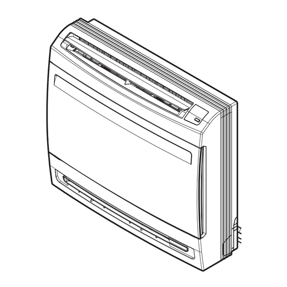
Console type indoor unit
Hide thumbs
Also See for Multi V Series:
- User manual ,
- Owner's manual (266 pages) ,
- Engineering manual (203 pages)
Table of Contents
Advertisement
Quick Links
INSTALLATION MANUAL
AIR CONDITIONER
• Please read this installation manual completely before installing the product.
• Installation work must be performed in accordance with the national wiring
standards by authorized personnel only.
• Please retain this installation manual for future reference after reading it
thoroughly.
TYPE : CONSOLE
P/NO : MFL61971203
www.lg.com
Advertisement
Table of Contents

Subscribe to Our Youtube Channel
Related Manuals for LG Multi V Series


Summary of Contents for LG Multi V Series
-
Page 1: Installation Manual
• Please read this installation manual completely before installing the product. • Installation work must be performed in accordance with the national wiring standards by authorized personnel only. • Please retain this installation manual for future reference after reading it thoroughly. TYPE : CONSOLE www.lg.com P/NO : MFL61971203... -
Page 2: Table Of Contents
Console Type Indoor Unit Installation Manual TABLE OF CONTENTS Required Parts Required Tools Installation Requirements Installation Parts ....3 Safety Precautions....4 Installation o Installation guide map o Level gauge o Screw driver Selection of the Best Location...7 o Electric drill o Hole core drill Indoor unit installation....8 o Horizontal meter o Connecting cable... -
Page 3: Installation Parts
Installation Parts Installation Parts Air filter Signal receiver Operation lamp Air purifier lamp ON/OFF button Air outlet Air inlet Allergy filter Installation Clamp Name Drain Hose Other Plate (Tie wrap) Quantity 1 EA 1 EA 4 EA - Allergy Filter - Fixing screw for Installation Plate 4*25 mm-5EA - Wood screw for indoor... -
Page 4: Safety Precautions
Safety Precautions Safety Precautions To prevent injury to the user or other people and property damage, the following instructions must be followed. n Be sure to read before installing the air conditioner. n Be sure to observe the cautions specified here as they include important items related to safety. n Incorrect operation due to ignoring instruction will cause harm or damage. - Page 5 Safety Precautions Do not modify or extend the Do not let the air conditioner Be cautious when unpacking power cable. run for a long time when the and installing the product. humidity is very high and a door or a window is left open. •...
-
Page 6: Installation
Installation Installation Read completely, then follow step by step. Selection of the Best Location • There should not be any heat source or steam near the unit. • There should not be any obstacles to the air circulation. • A place where air circulation in the room will be good. •... -
Page 7: Indoor Unit Installation
Installation Indoor unit installation 1. Preparation / Removing front panel 1. Open the front grille by pulling forward 2. Then pull out the link of grille from groove in front panel. 3. Then pull out 2 hinges of grille from grooves in front panel. 4. -
Page 8: Refrigerant Piping
Installation 3. Refrigerant Piping 1. The location of hole is different depending on which side of the pipe is taken out. 2. Drill a hole(Ø70mm) in the point indicated by symbol in the illustration as below. Wall Left bottom piping Right bottom piping Left back piping Right back piping... -
Page 9: Drill A Hole In The Wall
Installation 4. Drill a Hole in the wall • Drill the piping hole with a ø70mm hole core drill. Drill the piping hole at either the right or the left WALL with the hole slightly slanted to the outdoor side. Indoor Outdoor 5. -
Page 10: Installing Indoor Unit
Installation 6. Installing Indoor unit 6-1 Installation on the Floor. 1. Fix up using 6 screws for floor installation. (700) 30.5 6 screw (M4*25L) 30.5 (Unit : mm) 6-2 Installation on the Wall 1. Fix up the installation plate using 5 screws and the indoor unit using 4 screws. 2. - Page 11 Installation 6-3 Half concealed installation. 1. Make a wall hole of the size shown Fig-1. Wall Supplemental plate Supplemental plate (Field supply) (Field supply) Hole (Unit : mm) <Fig - 1> 1) Normal concealed 2) Deep concealed 2. Installation of supplemental plate for attaching main unit •...
- Page 12 Installation 3.Piping Hole Wall Left bottom piping Right bottom piping Left pipng Wall (Unit : mm) 4. Remove the Deco Covers and Fixing Indoor Unit 1) Remove the Deco Covers. 2) Insert the Indoor Unit to the Wall hole. 3) Secure using 6 screws. (shown in the illus- tration) NOTICE - Check the horizon of Indoor unit with the wall.
-
Page 13: Flaring Work
Installation Flaring Work Main cause for gas leakage is due to defect of flaring work. Carry out correct flaring work in the following proce- dure. Cut the pipes and the cable. 1. Use the piping kit accessory or the pipes purchased Copper locally. -
Page 14: Connecting The Piping
Installation Connecting the Piping When you connect the refrigerant pipe, it is easier that you connect the gas pipe first. 1. Hold up the Sensor Link. 2. Separate the Pipe Bracket (2 screws) 3. Connect the refrigerant pipe. (Refer to next page) 4. - Page 15 If the drain hose is routed inside the room insu- late the hose with an insulation material* so that dripping from sweating (condensation) will not damage furniture or floors. Tape * Foamed polyethylene or equivalent is recom- Connecting mended. cable Drain hose Connecting pipe Connecting the installation pipe and...
-
Page 16: Wiring Connection
Installation Wiring Connection • Connect the wires to the terminals on the control board individually according to the outdoor unit connection. • Ensure that the color of the wires of outdoor unit and the terminal No. are the same as those of indoor unit respectively. Terminal block of outdoor unit Outdoor unit Indoor unit Central controller... -
Page 17: Installation Of Wired Remote Controller
Installation Installation of Wired Remote Controller 1. Please fix tightly using provided screw after placing remote controller setup board on the place where you like to setup. - Please set it up not to bend because poor setup could take place if setup board bends. Please set up remote controller board fit to the reclamation box if there is a reclamation box. - Page 18 4. Please connect indoor unit and remote controller using connecting cable. Please check if connector is normally connected. Indoor Unit side Connecting cable 5. Please use extension cable if the distance between wired remote controller and indoor unit is more than 10m.
-
Page 19: Installer Setting -Thermistor
Installation Installer Setting -Thermistor This is the function to select the temperature sensor to judge the room temperature. If pressing button long for 3 seconds, it enters into remote controller setter setup mode. - If pressing once shortly, it enters into user setup mode. -
Page 20: Dip Switch Setting
Installation Dip Switch Setting Function Description Setting Off Setting On Default Communication N/A (Default) Cycle N/A (Default) Group Control Selection of Master or Slave Master Slave Dry Contact Mode Selection of Dry Contact Wired/Wireless remote Mode controller Auto Selection of Manual or Auto operation Mode Installation Fan continuous operation... -
Page 21: Group Control Setting
Installation Group Control Setting 1. Group Control 1 Wired remote controller 1 + Standard Indoor Units LGAP Network System Slave Master Slave Signal Slave 12 V Display Error Message Only connect serial signal and GND lines between slave indoor unit Master Dip Switch in PCB (Cassette and Duct Type indoor units) - No. - Page 22 Installation 5. In case of any error occurs at indoor unit, display on the wired remote controller. Exception of the error indoor unit, an individual indoor unit control possibility. 6. In case of Group Control, it is possible to use following functions. - Selection of operation options (operation/stop/mode/set temperature) - Control of flow rate (High/Middle/Low) - It is not possible at some functions.
- Page 23 Installation 3. Group Control 3 Mixture connection with indoor units and Fresh Air Intake Unit LGAP Network System Signal Master Slave Master Slave 12 V Display Error Message Master Master In case of connecting with standard indoor unit and Fresh Intake Unit, separate Fresh Air Intake Unit with standard units.
-
Page 24: Remote Control
Installation 4. 2 Remote Control Wired remote controller 2 + Indoor unit 1 LGAP Network System Master Display Error Message Master Slave 1. It is possible to connect two wired remote controllers with one indoor unit. 2. Every types of indoor unit is possible to connect two remote controller. 3. - Page 25 Installation 5. Accessories for group control setting It is possible to set group control by using below accessories. Indoor unit 2 EA +Wired remote controller Indoor unit 1 EA +Wired remote controller 2EA ❈ PZCWRCG3 cable used for connection ❈ PZCWRC2 cable used for connection S lave Mas te r PZC WRC 2...
Need help?
Do you have a question about the Multi V Series and is the answer not in the manual?
Questions and answers