Advertisement
ENGLISH
Manufacturer :
FAAC S.p.A.
Address:
Via Benini, 1 - 40069 Zola Predosa BOLOGNA - ITALY
Declares that:
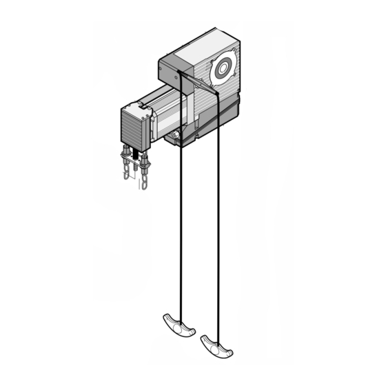
Operator mod. 540 and 541
• is manufactured to be incorporated in a machine or for assembly with other machines to constitute a machine
under the provisions of Directive 89/392/EEC, and subsequent amendments 91/368/EEC, 93/44/EEC, 93/68/
EEC;
• conforms to the essential safety requirements of the following further EEC Directives:
73/23/EEC and subsequent amendment 93/68/EEC.
89/336/EEC and subsequent amendment 92/31/EEC and 93/68/EEC
and, furthermore, declares that putting the machine into service is forbidden until the machine in which it
will be incorporated or of which it will become a part has been identified and it has been declared as
conforming to the conditions of Directive 89/392/EEC and subsequent amendments enacted by the national
implementing legislation.
Bologna, 01 January 2003
1) ATTENTION! To ensure the safety of people, it is important that you read
all the following instructions. Incorrect installation or incorrect use of the
product could cause serious harm to people.
2) Carefully read the instructions before beginning to install the product.
3) Do not leave packing materials (plastic, polystyrene, etc.) within reach of
children as such materials are potential sources of danger.
4) Store these instructions for future reference.
5) This product was designed and built strictly for the use indicated in this
documentation. Any other use, not expressly indicated here, could
compromise the good condition/operation of the product and/or be a
source of danger.
6) FAAC declines all liability caused by improper use or use other than that for
which the automated system was intended.
7) Do not install the equipment in an explosive atmosphere: the presence of
inflammable gas or fumes is a serious danger to safety.
8) The mechanical parts must conform to the provisions of Standards EN 12604
and EN 12605.
For non-EU countries, to obtain an adequate level of safety, the Standards
mentioned above must be observed, in addition to national legal regulations.
9) FAAC is not responsible for failure to observe Good Technique in the
construction of the closing elements to be motorised, or for any deformation
that may occur during use.
10) The installation must conform to Standards EN 12453 and EN 12445.
For non-EU countries, to obtain an adequate level of safety, the Standards
mentioned above must be observed, in addition to national legal regulations.
11) Before attempting any job on the system, cut out electrical power .
12) The mains power supply of the automated system must be fitted with an all-
pole switch with contact opening distance of 3mm or greater. Use of a 6A
thermal breaker with all-pole circuit break is recommended.
13) Make sure that a differential switch with threshold of 0.03 A is fitted upstream
of the system.
CE DECLARATION OF MACHINE CONFORMITY
(DIRECTIVE 89/392/EEC, ANNEX II, PART B)
The Managing Director
WARNINGS FOR THE INSTALLER
GENERAL SAFETY OBLIGATIONS
A. Bassi
14) Make sure that the earthing system is perfectly constructed, and connect
metal parts of the means of the closure to it.
15) The safety devices (EN 12978 standard) protect any danger areas against
mechanical movement Risks, such as crushing, dragging, and shearing.
16) Use of at least one indicator-light (e.g. FAACLIGHT ) is recommended for
every system, as well as a warning sign adequately secured to the frame
structure, in addition to the devices mentioned at point "15".
17) FAAC declines all liability as concerns safety and efficient operation of
the automated system, if system components not produced by FAAC are
used.
18) For maintenance, strictly use original parts by FAAC.
19) Do not in any way modify the components of the automated system.
20) The installer shall supply all information concerning manual operation of
the system in case of an emergency, and shall hand over to the user the
warnings handbook supplied with the product.
21) Do not allow children or adults to stay near the product while it is operating.
22) Keep remote controls or other pulse generators away from children, to
prevent the automated system from being activated involuntarily.
23)
Transit under the door is permitted only when the automated system is idle.
24) The user must not attempt any kind of repair or direct action whatever
and contact qualified personnel only.
25)
Maintenance: check at least every 6 months the efficiency of the system,
particularly the efficiency of the safety devices (including, where foreseen,
the operator thrust force) and of the release devices.
26) Anything not expressly specified in these instructions is not permitted.
9
ENGLISH
Advertisement
Table of Contents

Related Manuals for FAAC 540

Summary of Contents for FAAC 540
- Page 1 19) Do not in any way modify the components of the automated system. 6) FAAC declines all liability caused by improper use or use other than that for which the automated system was intended. 20) The installer shall supply all information concerning manual operation of...
-
Page 2: Technical Specifications
Df in millimetres. For example, if a door can be moved with a force of system (in models for which it is supplied) make it possible to 60daN and the drum diameter is 170 mm, a 540 with chain transmission of 1:1.5 move the door in case of a power cut or malfunction. -
Page 3: Preliminary Checks
3. ELECTRICAL EQUIPMENT ARRANGEMENT Figure 3 shows the layout of the electrical equipment required 4. PRELIMINARY CHECKS for installing the 540 operator. The door structure must be suitable to be automated and must Figure 4 shows the layout of the electrical equipment required conform to standards EN12604 and EN 12605. -
Page 4: Installing The Operator
The securing plate can be installed on any of the operator’s The 540 operator has a 25.4 mm (1”) power take-off. If the drive two sides. shaft is of a different size, the chain transmission (optional item) must be installed. - Page 5 ENGLISH ENGLISH 5.3 INSTALLING THE OPERATOR 5.4 WINCH ADJUSTMENT •Release the operator with the appropriate lever. Fully unwind the supplied chain and unite one of its ends to the •Fit the securing plate on the operator without tightening the one already inserted in the winch, using one of the supplied screws.
- Page 6 ENGLISH ENGLISH is not prevented or interrupted by the tripping of the winch’s Fit the lever and make sure that it reaches the travel limits in the safety microswitch. two directions, at an inclination of about 45-50°. We advise you to create an anchoring point for the lower part Fit the lever fixing screw.
-
Page 7: Electrical System
To prevent any electric noise whatever, use separate sheaths. Move the door by hand to open position until the mechanical The 540 operator is supplied with the 200BT equipment on board. buffers are slightly compressed. The 541 operator is supplied with an on-board inter-connection Lift up the spring, turn the ring-nut of the opening limit-switch board. -
Page 8: Maintenance
If the operator is supplied with a winch, fix - in the immediate vicinity of the chain - the sticker indicating the traction directions for the opening and closing manual manoeuvres. 7.1 540 and 541 with 200BT equipment • Run a few complete cycles to check the efficiency of the automated system. -
Page 9: General Safety Regulations
• In the event of malfunctions, manually activate or release the The 540 and 541 operators are provided with an emergency system door to allow access and wait for qualified technical personnel which can be activated from the inside.
Need help?
Do you have a question about the 540 and is the answer not in the manual?
Questions and answers