
Summary of Contents for Ultimarc AimTrak Light Gun
- Page 1 Bluetooth Light Gun Please also see the Aimtrak Setup Guide at : www.ultimarc.com/AimTrak Setup Guide.pdf...
-
Page 2: Table Of Contents
Contents Section 1: Introduction ......................3 Features ..........................3 Bluetooth SIG Qualification................... 3 Section 2: Charging......................4 Section 3: Bluetooth Host Connectivity ................4 Tested Host Systems ....................... 4 Connecting to the Host....................5 Recovering from no-connect situation or device not being correctly detected....6 Section 3: Configuration ..................... -
Page 3: Section 1: Introduction
Section 1: Introduction Features • No special drivers or application changes needed. • Configuration utility allows the trigger and buttons to be configured as gamepad buttons or mouse buttons. • Configuration information is sent “over-the-air” from a PC equipped with a standard Bluetooth interface. -
Page 4: Section 2: Charging
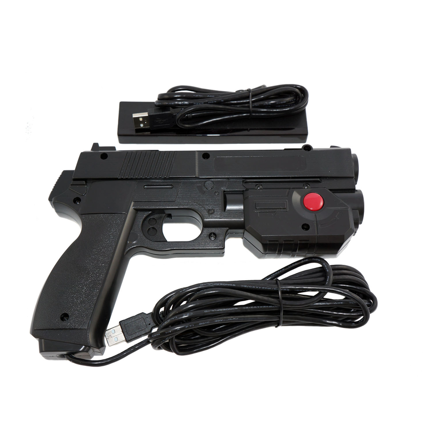
Section 2: Charging A USB charging cable is provided, which can be plugged into any USB charger or port. Charging is rapid and should be completed in 30 mins or so. Important note: The unit is designed to only be charged rather than used when connected to a USB port. -
Page 5: Connecting To The Host
Connecting to the Host When the Aimtrak is powered up, or when trigger is activated, the board will start to advertise its presence to the host system. During this time, the host needs to be told to search for devices. It should discover the device: The next step is to select the device and pair with it. -
Page 6: Recovering From No-Connect Situation Or Device Not Being Correctly Detected
Recovering from no-connect situation or device not being correctly detected. The device should show as an additional HID mouse in device manager. To reset the device and connection and clear bind information, open Device Manager in Windows and right click and uninstall the Bluetooth Radio as shown. Do not check the “delete drivers”... -
Page 7: Section 3: Configuration
Section 4: Bluetooth Configuration These settings are located on the “Configuration” tab of the Aimtrak utility The slider defines how many seconds of no-activity elapse before the unit disconnects the Bluetooth link. Or you can opt to have the device never disconnect but this will consume much more battery power. -
Page 8: Section 4: Upgrading Firmware
4. Accept the OK prompt. 5. Open the “Bluetooth devices” dialog in Windows 6. Search for new devices. An “Ultimarc Loader” device should be found. 7. Click on the new device to bind to it. 8. If not already running, go to the U-Config install folder and run the program called “Blueupload.exe”. - Page 9 Section 6: Fitting Upgrade Kit Note this kit does not support recoil and we do not recommend fitting it to a recoil-equipped unit. USB and Bluetooth devices can be used together on one host but the Aimtrak software utility will not function with both connected. Kit contents: Replacement sensor module Charging cable...
- Page 10 Place unit on desk as shown and remove 7 screws. Lift off top (Right side) Remove existing sensor module and USB cable. These are no longer required.
- Page 11 The next step depends on version. Later housing versions will not require this step as they are already modified in production, in preparation for this kit. If the housing is older, it will have a number of internal ribs which need to be removed.
- Page 12 Remove adhesive cover transparent foil from front of sensor module lens. Fit the charging board, connect power cable to module and fit the module. Connect battery. Cut the supplied silicone foam into two pieces and place each side of battery in the position shown.
Need help?
Do you have a question about the AimTrak Light Gun and is the answer not in the manual?
Questions and answers