
Related Manuals for Agilent Technologies 5530


Summary of Contents for Agilent Technologies 5530
- Page 1 A g i l e n t 5 5 3 0 D y n a m i c C a l i b r a t o r G e t t i n g S t a r t e d G u i d e...
- Page 3 Getting Started Guide Agilent 5530 Dynamic Calibrator...
- Page 4 Do not General proceed beyond a CAUTION Certification until the indicated conditions This product and related Agilent Technologies, Inc. are fully understood and met. documentation must be Indicates hazardous voltages. certifies that this product met reviewed for familiarization...
-
Page 5: Table Of Contents
Contents Contents About This Guide Introducing the Agilent 5530 Introduction Overview of the Agilent 5530 System Overview Overview of Laser Calibration Types of Measurements Making Laser Measurements Safely Introduction Safety Labeling General Safety Precautions Using the Laser Head Safely Using Components Safely... - Page 6 Agilent 10888A Remote Control Unit 3-16 Agilent 10887-60202 A-quad-B Cable Assembly 3-17 Connecting and Turning on Power 3-18 Using the Agilent 5530 for the First Time Introduction Task 1: Assembling and Connecting Components Task 2: Setting Up the Software Task 3: Aligning the Optics...
- Page 7 Contents Setting Up the Laser Software for Your Measurement 5-17 Verifying the hardware setup Testing the remote control unit Setting up environmental compensation Defining laser parameters Resetting the laser position Setting Up Your Measurement 5-22 Making the Measurement Introduction Mounting the Laser Head on the Tripod Collecting Measurement Data Recording Measurement Data Erasing Measurement Data...
- Page 8 Optimizing Repeatability From One Calibration to the Next 8-13 Improving Resolution 8-14 Troubleshooting and Maintenance Introduction Troubleshooting the Agilent 5530 Maintaining the Agilent 5530 Maintaining the optics Cleaning with pressurized air Cleaning with lens tissue and methanol or alcohol Maintaining the air sensor Cleaning...
- Page 9 Contents Maintaining material temperature sensor Cleaning Checking accuracy quickly Returning sensors to Agilent for calibration Agilent Service Agreement Glossary Index Getting Started Guide...
- Page 10 Contents viii Getting Started Guide...
- Page 11 About This Guide The Agilent 5530 Dynamic Calibrator Getting Started Guide explains to first-time users how to set up and use the Agilent 5530 to perform a simple linear measurement (on your desk or bench instead of on a machine). It also provides an overview of the Agilent 10747F Metrology Software, guidelines for ensuring consistent accuracy, and troubleshooting and maintenance procedures.
- Page 12 About This Guide Chapter 5 Setting Up the Software for a Measurement — Explains how to access and use the metrology software. It also explains how to set up the software for a measurement. Chapter 6 Making the Measurement — Explains how to use the metrology software to make a measurement and collect data.
-
Page 13: Introducing The Agilent 5530
Introducing the Agilent 5530... -
Page 14: Introduction
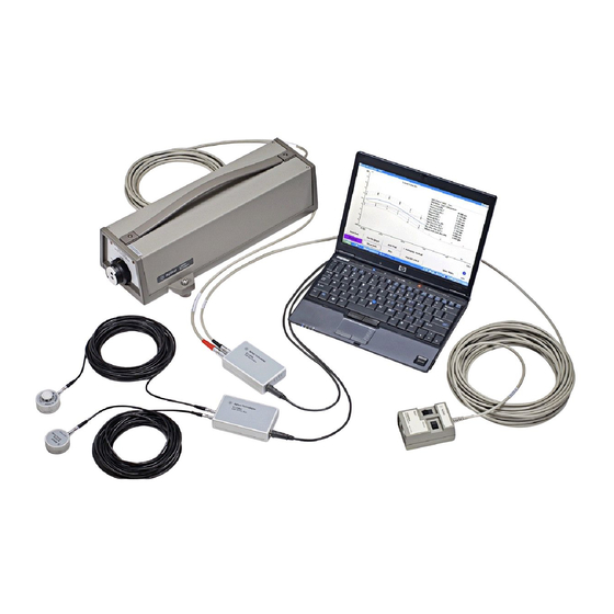
Chapter 1 Introducing the Agilent 5530 Introduction Introduction This chapter provides an overview of the Agilent 5530 Dynamic Calibrator and briefly describes the types of measurements you can make with it. Figure 1-1 shows the various components used in a typical system configuration. -
Page 15: Overview Of The Agilent 5530
Overview of the Agilent 5530 Overview of the Agilent 5530 The Agilent 5530 Dynamic Calibrator is a laser system used to ensure the accuracy of a machine’s motion and positioning. Controlled through your PC (with the Microsoft® Windows operating system installed), the system is able to collect and analyze measurement data for a number of measurements. -
Page 16: System Overview
Chapter 1 Introducing the Agilent 5530 System Overview System Overview The Agilent 5530 Dynamic Calibrator System typically includes the following components: • measurement optics such as reflector, retroreflector, turning mirror, and interferometer • Agilent 5519A/B Laser Head • Agilent 10753B Tripod •... -
Page 17: Overview Of Laser Calibration
90 degree reference (the optical square). The Agilent 5530 uses a laser to provide the data you need to accurately analyze the machine’s geometry. Laser measurement systems provide high accuracy over long distances—up to 80 meters (260 feet) with long range optics —... - Page 18 Chapter 1 Introducing the Agilent 5530 Overview of Laser Calibration measurement systems provide higher accuracy than other types of calibration systems. The Agilent 5530 offers even more reliability because it uses Agilent’s two-frequency laser technique, which virtually eliminates problems resulting from changes in beam intensity.
-
Page 19: Types Of Measurements
Chapter 1 Introducing the Agilent 5530 Types of Measurements Types of Measurements The Agilent 5530 dynamic calibrator performs the following types of measurements: • Linear measurements made in a straight line along a single axis. They indicate whether your machine is accurately measuring distances where the laser beam is located. - Page 20 Chapter 1 Introducing the Agilent 5530 Types of Measurements Getting Started Guide...
-
Page 21: Making Laser Measurements Safely
Making Laser Measurements Safely... -
Page 22: Introduction
This chapter provides safety guidelines you must follow to help ensure your protection and the protection of the equipment. Familiarize yourself with all these guidelines before setting up or using the Agilent 5530. Safety Labeling The following symbols appear on the Agilent 5530: When you see this symbol, refer to the instruction manual for help. -
Page 23: General Safety Precautions
General Safety Precautions Before turning on the power to any component of the Agilent 5530 system, make sure it is plugged into a protective grounded socket. Tampering with a protective (grounding) conductor or disconnecting the protective earth terminal causes a potential shock hazard. -
Page 24: Using The Laser Head Safely
Using Components Safely When using any Agilent 5530 calibrator system’s electronic component (including the laser head, air and temperature sensors, and remote control unit), observe the following guidelines: •... -
Page 25: Protecting The Optics
• Do not open the casings on the sensors. Protecting the Optics Although the Agilent 5530 calibration system’s optics are rugged, there is a possibility they can be damaged by the following conditions: • hard impact or excessive force—either from dropping or machine movement •... - Page 26 Chapter 2 Making Laser Measurements Safely Protecting the Optics Getting Started Guide...
-
Page 27: Installing The Software And Connecting Components
Installing the Software and Connecting Components... -
Page 28: Introduction
Chapter 3 Installing the Software and Connecting Components Introduction Introduction This chapter first explains how to install the metrology software. It then explains how to connect the following components to your personal computer (PC): the laser head, air and material temperature sensors, and optional remote control unit and A-quad-B input. - Page 29 Chapter 3 Installing the Software and Connecting Components Installing the Metrology Software Figure 3-1. Vista Operating System Type If your PC is running Windows Vista (32-bit), you must install and enable winhelp32.exe, as follows: You must be logged on to your PC as an administrator. Navigate to the Microsoft download center by connecting to the Microsoft web site at www.microsoft.com and clicking on the appropriate link(s).
-
Page 30: Installing The Software
Chapter 3 Installing the Software and Connecting Components Installing the Metrology Software Installing the software To install the metrology software, follow these steps: If you haven’t already done so, turn on your PC. Insert the Agilent 10747F Metrology Software CD, which came with the product, into the PC’s CD-ROM drive. -
Page 31: To Start The Metrology Software (General)
2. Select Programs on the pop-up menu, see Figure 3-3) 3. Select the Laser Metrology group. 4. Select Laser Metrology (see Figure 3-3), then select the 5530 icon. To exit the Metrology Software (general) To exit the software, follow these steps: Return to the Main Menu, then select Quit. -
Page 32: Connecting The Axis Module And Sensor Hub
Chapter 3 Installing the Software and Connecting Components Connecting the Axis Module and Sensor Hub Connecting the Axis Module and Sensor Hub After installing the software, connect the E1735A USB Axis Module and E1736A USB Sensor Hub to the USB ports on your PC. The steps for connecting either the Axis Hub or the Sensor Module to the PC are identical. - Page 33 Chapter 3 Installing the Software and Connecting Components Connecting the Axis Module and Sensor Hub 3. Next connect the USB cable from the Axis Module to a USB port on your PC, or a powered USB 2.0 port connected to your PC. 4.
- Page 34 Chapter 3 Installing the Software and Connecting Components Connecting the Axis Module and Sensor Hub 6. On the new screen that appears, answer the question “What do you want the wizard to do?” by selecting the radio button “Install from a list or specific location (Advanced)”...
- Page 35 Chapter 3 Installing the Software and Connecting Components Connecting the Axis Module and Sensor Hub 8. On the new screen that appears, select the radio button “Search for the best driver in these locations.” Below this selection, check the box for “Search removable media (floppy, CD-ROM...)”...
- Page 36 Chapter 3 Installing the Software and Connecting Components Connecting the Axis Module and Sensor Hub 10. The new screen that appears should indicate that the driver for the Axis Module has been found and installed on your PC (see Figure 3-8). Click on Finish to close the wizard.
-
Page 37: Communication Leds
Chapter 3 Installing the Software and Connecting Components Connecting the Sensors Communication LEDs The LEDs on the E1735A Axis Module and the E1736A Sensor Hub (see Figure 3-4) indicate the following conditions: LED indicator device driver is working driver not installed H.S. - Page 38 Chapter 3 Installing the Software and Connecting Components Connecting the Sensors The connectors at either end of a sensor cable are identical. To connect the sensor cables to the sensors, line up the red mark on the cable connector with the red mark on the sensor connector (on the bottom side of the sensor) and insert the cable connector.
- Page 39 Chapter 3 Installing the Software and Connecting Components Connecting the Sensors 1 - 4 Sensor connection ports 5 Agilent E1736A USB Sensor Hub 6 Cable connector alignment mark (x4) n s o n s o n s o n s o Figure 3-10.
-
Page 40: Connecting The Laser
Chapter 3 Installing the Software and Connecting Components Connecting the Laser Connecting the Laser This section explains how to connect the laser head to the system. The Agilent 10882A,B,C cable connects the laser head to the USB Axis Module. The connectors on both ends of the cable are the same. NOTE Do not set up the laser on the tripod at this time. - Page 41 If you are not using the optional remote control unit, and if you do not wish to connect an encoder to the 5530 Dynamic Calibrator, then you are ready to power up the system. Proceed to the section “Connecting and Turning on Power”...
-
Page 42: Agilent 10888A Remote Control Unit
Chapter 3 Installing the Software and Connecting Components Agilent 10888A Remote Control Unit Agilent 10888A Remote Control Unit The optional Agilent 10888A Remote Control Unit includes a non- removable 15-meter (49-foot) cable that plugs into the Agilent E1735A USB Axis Module. To connect the cable, line up the red mark on the cable connector with the small circle above the port labelled “Remote”... -
Page 43: Agilent 10887-60202 A-Quad-B Cable Assembly
Chapter 3 Installing the Software and Connecting Components Agilent 10887-60202 A-quad-B Cable Assembly Agilent 10887-60202 A-quad-B Cable Assembly This 3-meter (10-foot) cable connects your machine’s A-quad-B encoder output to the Agilent E1735A USB axis module’s A-quad-B input port. The cable is supplied with a mating connector for the Agilent E1735A module on one end. -
Page 44: Connecting And Turning On Power
Chapter 3 Installing the Software and Connecting Components Connecting and Turning on Power Connecting and Turning on Power To connect power and turn on the system, see Figure 3-12 and follow these steps: Connect the laser head power cord to the three-prong outlet on the rear panel of the laser head (see Figure 3-12). -
Page 45: Using The Agilent 5530 For The First Time
Using the Agilent 5530 for the First Time... -
Page 46: Introduction
This chapter steps you through a simplified linear measurement you can perform on a table or desktop. This tutorial will allow you to get comfortable with the Agilent 5530 before you set it up on a machine to make an actual calibration. For this tutorial, you need a straightedge and the measurement template provided on page 4-21, in addition to the Agilent 5530 components. -
Page 47: Task 1: Assembling And Connecting Components
Chapter 4 Using the Agilent 5530 for the First Time Task 1: Assembling and Connecting Components Task 1: Assembling and Connecting Components To set up the hardware for this tutorial, follow these steps: Print the measurement template provided on page 4-21. - Page 48 Chapter 4 Using the Agilent 5530 for the First Time Task 1: Assembling and Connecting Components Linear retroreflector Height adjuster and post Base Linear interferometer Figure 4-2. Assembling the interferometer Place the interferometer assembly about 1 cm (1/2 inch) away from the straightedge approximately 5 cm (2 inches) from the front of the laser head as shown in Figure 4-1.
- Page 49 Chapter 4 Using the Agilent 5530 for the First Time Task 1: Assembling and Connecting Components Place the retroreflector as close as possible to the interferometer assembly without allowing the two to touch. Mark the positions of the interferometer assembly and retroreflector on the template with a pencil or piece of tape.
-
Page 50: Task 2: Setting Up The Software
Chapter 4 Using the Agilent 5530 for the First Time Task 2: Setting Up the Software Task 2: Setting Up the Software NOTE The following instructions assume that you have the Agilent 10747F Metrology Software installed on your computer and you know how to use Microsoft Windows. - Page 51 Chapter 4 Using the Agilent 5530 for the First Time Task 2: Setting Up the Software Figure 4-4. Sample Windows screen showing the metrology menu Open the metrology software by selecting Agilent 5530 Dynamic Calibrator as shown in Figure 4-4.
- Page 52 Chapter 4 Using the Agilent 5530 for the First Time Task 2: Setting Up the Software Figure 4-5. Metrology Main Menu Select the Linear button. To select a button if you have a mouse, place the cursor on the button and press the mouse button once (click).
- Page 53 Chapter 4 Using the Agilent 5530 for the First Time Task 2: Setting Up the Software Figure 4-6. Set Up Laser: LINEAR screen If the Position Units field (to the right of the Measurement Axis diagram) is not set to mm, follow these steps: a.
-
Page 54: Task 3: Aligning The Optics
Chapter 4 Using the Agilent 5530 for the First Time Task 3: Aligning the Optics Task 3: Aligning the Optics In this procedure, you make sure that the optics are aligned with the laser beam path and with each other. Follow these steps: Set the turret ring on the laser head to OTHER (Figure 4-7). - Page 55 Chapter 4 Using the Agilent 5530 for the First Time Task 3: Aligning the Optics Adjust the interferometer assembly’s position so that its return beam is centered on the laser head’s target in the lower port. Adjust the retroreflector’s position so that its return beam is centered on the laser head’s target.
- Page 56 Chapter 4 Using the Agilent 5530 for the First Time Task 3: Aligning the Optics If the beam strength falls to 60 percent or below, realign the optics by repeating steps 1 through 5.Move the retroreflector to the end of the straightedge (at least 75 mm;...
-
Page 57: Task 4: Making The Measurements
Chapter 4 Using the Agilent 5530 for the First Time Task 4: Making the Measurements Task 4: Making the Measurements In this section you will make three measurements. Follow these steps: On the Set Up Laser: LINEAR screen, select Set Up Meas. - Page 58 Chapter 4 Using the Agilent 5530 for the First Time Task 4: Making the Measurements In the Travel Mode box, select Unidirectional. In the Start Position field, type 0, which stands for 0 mm; this is the position you will move the retroreflector to first. To enter information in a field, first select the field, then type the information.
- Page 59 Chapter 4 Using the Agilent 5530 for the First Time Task 4: Making the Measurements Figure 4-9. Collect Data: LINEAR screen On the screen, select Record. Move the retroreflector 25 mm (1 inch) away from the interferometer assembly. On the screen, select Record.
- Page 60 Chapter 4 Using the Agilent 5530 for the First Time Task 4: Making the Measurements NOTE If the Laser Position is not within the Target Window of the Target: millimeters position, then the red "Outside Target Window" label is displayed and the record function disabled.
-
Page 61: Task 5: Displaying And Saving Data
Chapter 4 Using the Agilent 5530 for the First Time Task 5: Displaying and Saving Data Figure 4-10. Analyze Data: LINEAR screen Task 5: Displaying and Saving Data There are a number of ways you can use the data you collected during your measurement. - Page 62 Chapter 4 Using the Agilent 5530 for the First Time Task 5: Displaying and Saving Data The system also allows you to display the following information for each measurement point: • the actual measurement recorded • the target position •...
-
Page 63: Saving Data
Chapter 4 Using the Agilent 5530 for the First Time Task 5: Displaying and Saving Data Saving data To save your measurement data, follow these steps: Select Main Menu. The Metrology Main Menu is displayed. Select Save Data. The Save Data screen is displayed (Figure 4-12). -
Page 64: Task 6: Exiting The Metrology Software
Chapter 4 Using the Agilent 5530 for the First Time Task 6: Exiting the Metrology Software a. Select the down arrow on the right side of the Disk Drives box. b. Select a disk drive. If necessary, in the Directories box, select the directory in which you want to save the data. - Page 65 Measurement Template 1 Laser feet positions 2 @ Straightedge position Getting Started Guide 4-21...
-
Page 67: Setting Up The Software For A Measurement
Setting Up the Software for a Measurement... -
Page 68: Introduction
This chapter covers the first function; chapters 6 and 7 cover the second and third. Figure 5-1 provides an overview of the metrology software screens. The specific instructions required to use the software to make a measurement are presented in the Agilent 5530 Dynamic Calibrator Measurements Reference Guide. Getting Started Guide... - Page 69 Chapter 5 Setting Up the Software for a Measurement Introduction Quit Save Data Main Menu Are You Sure? Save Recall Previous Quit Data Data Screen Exit Program Recall Data Setup Other Setup Other Measurements Only & Data Time- Square Parallel Diagonal Base Laser Diagram...
-
Page 70: Terms To Know
Chapter 5 Setting Up the Software for a Measurement Terms to Know Terms to Know Before using the metrology software, you should be familiar with the following terms and concepts: • arrow cursor—The mouse cursor is an arrow when the software is idle and the cursor is not on a field that requires a keyboard or remote control entry. - Page 71 Chapter 5 Setting Up the Software for a Measurement Terms to Know • hourglass cursor—The mouse cursor looks like an hourglass when the software is busy processing a command. The cursor changes back to one of the other icons when processing is completed. Mouse clicks are ignored until processing is completed.
-
Page 72: Conventions Used In The Software
Chapter 5 Setting Up the Software for a Measurement Conventions Used in the Software NOTE Since individual PCs vary slightly, you may need to adjust the software instructions for your PC. For example, the Enter key is labeled Return on some keyboards. -
Page 73: Using Buttons
Chapter 5 Setting Up the Software for a Measurement Using Online Help After you have finished working in the Start menu window, click on the minimized metrology screen, which is located in the task bar at the bottom of the screen. The metrology screen that you were working on is maximized and displayed on your computer screen. -
Page 74: Accessing The Software
Chapter 5 Setting Up the Software for a Measurement Accessing the Software Press F1. The help text for that field is displayed in a new window. Close the help window by pressing the Alt key and the F4 key simultaneously or by using the mouse to “click” Exit on the File menu. To access online help for an entire screen or for a procedure, select the information (i) button. - Page 75 Chapter 5 Setting Up the Software for a Measurement Accessing the Software Figure 5-2. Sample Windows screen showing the metrology icon Open the metrology software by selecting Agilent 5530 Dynamic Calibrator. The Metrology Main Menu is displayed (Figure 5-3). Getting Started Guide...
-
Page 76: Selecting A Measurement Type
Chapter 5 Setting Up the Software for a Measurement Selecting a Measurement Type Figure 5-3. Metrology Main Menu Selecting a Measurement Type The Metrology Main Menu, shown in Figure 5-3, is your gateway to the Agilent 10747F Metrology Software. You start with this screen to perform the following functions: •... - Page 77 Chapter 5 Setting Up the Software for a Measurement Selecting a Measurement Type To make a linear, angular, or straightness measurement, select the button for that measurement. The Set Up Laser screen for that measurement type is displayed. Select the Other Meas button to display a menu of additional measurement types as shown in Figure 5-4.
-
Page 78: Recalling Saved Setup Files And Data Files
Chapter 5 Setting Up the Software for a Measurement Recalling Saved Setup Files and Data Files Recalling Saved Setup Files and Data Files You can easily recall a file containing measurement setup data and data saved from a previous measurement. The setup data is saved in the same file as the measurement data but can be recalled without recalling the measurement data. - Page 79 Chapter 5 Setting Up the Software for a Measurement Recalling Saved Setup Files and Data Files Figure 5-5. Recall Data screen If necessary, select the disk drive where the file is stored. Click the arrow, or press the Alt key and the down arrow key simultaneously, to display available disk drives.
-
Page 80: Saving Setup Data And Measurement Data Files
Chapter 5 Setting Up the Software for a Measurement Saving Setup Data and Measurement Data Files Select the file name on the list. Select one of the following buttons: • Setup and Data (Alt s)—recalls both the measurement setup data and the measurement data file. - Page 81 Chapter 5 Setting Up the Software for a Measurement Saving Setup Data and Measurement Data Files Figure 5-6. Save Data screen If necessary, select the disk drive where you want to store the file. Click the arrow, or press the Alt key and the down arrow key simultaneously, to display available disk drives.
-
Page 82: Exiting The Metrology Software
Chapter 5 Setting Up the Software for a Measurement Exiting the Metrology Software If you are entering a new file name, use a three-character file extension to indicate the type of measurement. For example, use one of the following: • “lin”... -
Page 83: Setting Up The Laser Software For Your Measurement
Chapter 5 Setting Up the Software for a Measurement Setting Up the Laser Software for Your Measurement Select Quit. A window is displayed asking if you are sure you want to quit. Select Yes to quit. Select No or press Enter to return to the Metrology Main Menu. -
Page 84: Verifying The Hardware Setup
Chapter 5 Setting Up the Software for a Measurement Setting Up the Laser Software for Your Measurement Figure 5-7. Set Up Laser: LINEAR screen Verifying the hardware setup The Set Up Laser screen automatically verifies the following: • The laser head is connected and is ready to make a measurement. •... -
Page 85: Testing The Remote Control Unit
Chapter 5 Setting Up the Software for a Measurement Setting Up the Laser Software for Your Measurement Testing the remote control unit On the remote control unit, press the Record button. If the remote control unit is working, the Test Record Button field on the Set Up Laser screen flashes when the Record button is pressed on the unit. -
Page 86: Defining Laser Parameters
Chapter 5 Setting Up the Software for a Measurement Setting Up the Laser Software for Your Measurement Figure 5-8. Set Up Environmental Compensation screen Defining laser parameters Selecting the Change Parameters button on the Set Up Laser screen (Figure 5-7) displays a screen (Figure 5-9) with option boxes where you can redefine the following parameters: •... - Page 87 Chapter 5 Setting Up the Software for a Measurement Setting Up the Laser Software for Your Measurement • Averaging —these buttons select the period over which data for each measurement point is averaged. Averaging results in a smoother, more stable numeric display (with a longer period yielding a more stable display).
-
Page 88: Resetting The Laser Position
Chapter 5 Setting Up the Software for a Measurement Setting Up Your Measurement Resetting the laser position There are three situations in which you need to reset the laser position: • You have aligned the optics and completed the laser setup and are ready to begin the measurement. - Page 89 Trigger—determines if the remote control, machine tool encoder, or an automatic trigger will signal the software to record a measurement. See the Agilent 5530 Dynamic Calibrator Measurements Reference Guide for information on selecting a triggering mode. The Record Button (manual) trigger is used unless Auto or Encoder is chosen.
- Page 90 Chapter 5 Setting Up the Software for a Measurement Setting Up Your Measurement • Set Up Targets—defines the target list. To display and edit the target list (Figure 5-11), press Show Targets. Figure 5-11. Set Up Measurement screen with Set Up Targets window open You are now ready to begin making the measurement.
-
Page 91: Making The Measurement
Making the Measurement... -
Page 92: Introduction
Introduction This chapter first explains how to mount the laser head on the tripod. Once you have set up the Agilent 5530’s hardware and the measurement portions of the software, you are ready to collect measurement data. Mounting the Laser Head on the Tripod... - Page 93 Chapter 6 Making the Measurement Mounting the Laser Head on the Tripod Laser head Handle Elevation adjustment nut Azimuth adjustment knob Slide adjustment knob Mounting plate retention screw Tripod Knob to lock height adjustment in place Leg locks Knob to stiffen leg support Height adjustment knob Knob to lock the...
- Page 94 Chapter 6 Making the Measurement Mounting the Laser Head on the Tripod If the legs are not fully extended or if the tripod is on a rough or uneven floor, use the bubble level on the mounting plate to ensure that the mounting plate is level.
- Page 95 Chapter 6 Making the Measurement Mounting the Laser Head on the Tripod Pedestals for laser head's front feet Flexure Bubble level Groove for laser head’s rear foot Azimuth adjustment screw Azimuth adjustment knob Slide adjustment for translating the laser head Slide adjustment knob Groove for lower edge of the mounting clamp...
- Page 96 Chapter 6 Making the Measurement Mounting the Laser Head on the Tripod Knurled knob for pedestal captive screw Elevation adjustment screw Elevation screw locknut Clamp for rear foot Figure 6-3. Securing the laser head to the mounting plate d. Raise the elevation screw locknut to hold the clamp in place. With the laser head secured to the mounting plate, ensure that: •...
-
Page 97: Collecting Measurement Data
Chapter 6 Making the Measurement Collecting Measurement Data Collecting Measurement Data Once you have set up the Agilent 5530’s hardware and the measurement portions of the software, you are ready to collect measurement data. On the Set Up Measurement screen, select Collect Data. -
Page 98: Recording Measurement Data
Chapter 6 Making the Measurement Recording Measurement Data The numeric displays are defined by the options selected in Upper Num. Display and Lower Num. Display. The top display indicates the actual laser position or actual error. The lower display indicates the target or encoder position. -
Page 99: Erasing Measurement Data
Chapter 6 Making the Measurement Erasing Measurement Data Erasing Measurement Data If, during your measurement, you record data you do not want or if you need to collect additional data, the metrology software enables you to erase one or more data points. Follow these steps: On the Collect Data screen, select Erase Data. - Page 100 Chapter 6 Making the Measurement Erasing Measurement Data Select one of the following options: • Erase last data point—erases the most recent measurement recorded and recalls the previous target value so you can retake the measurement. • Erase last data run—erases the current partial data run (or the last run if there is no data in the current run) and sets up data collection at the beginning of the run.
-
Page 101: Analyzing, Transferring, And Printing Measurement Data
Analyzing, Transferring, and Printing Measurement Data... -
Page 102: Introduction
Chapter 7 Analyzing, Transferring, and Printing Measurement Data Introduction Introduction The Agilent 10747F Metrology Software enables you to take the raw measurement data you collected and analyze the following machine characteristics: • accuracy • repeatability • mean backlash • slope This chapter describes how to use the system to make these analyses. -
Page 103: Displaying The Analyze Data Screen
Chapter 7 Analyzing, Transferring, and Printing Measurement Data Displaying the Analyze Data Screen Displaying the Analyze Data Screen To begin data analysis, select Analyze Data on the Collect Data screen. The Analyze Data screen is displayed (Figure 7-1). Figure 7-1. Analyze Data: LINEAR screen The Analyze Data screen presents graphical data and numerical analysis of the data set. -
Page 104: Changing The Data Display
Chapter 7 Analyzing, Transferring, and Printing Measurement Data Changing the Data Display To move the comment box, in which the results of the numerical analysis are displayed, to another part of the Analyze Data screen, follow these steps: Place the mouse cursor on the edge of the box. Press and hold the mouse button and drag the box where you want it displayed. -
Page 105: Displaying And Editing Measurement Data
Chapter 7 Analyzing, Transferring, and Printing Measurement Data Changing the Data Display To create a text box, follow these steps: a. Place the mouse cursor where you want one corner of the box to be located. b. Press and hold the mouse button. Then drag the cursor along a diagonal line to draw a box. - Page 106 Chapter 7 Analyzing, Transferring, and Printing Measurement Data Changing the Data Display NOTE Changing a measurement value on this screen also changes the value on the Analyze Data screen when the file is saved. To change an individual measurement value, follow these steps: In the table on the Show Data Set screen, highlight the value you want to change.
-
Page 107: Printing The Data Analysis Graph
Chapter 7 Analyzing, Transferring, and Printing Measurement Data Changing the Data Display Printing the data analysis graph To print the graph and numerical analysis after you have customized your data display, on the Analyze Data screen select Plot, then click Plot again in the pop-up Plot Type menu. -
Page 108: Transferring Data To Another Program
Chapter 7 Analyzing, Transferring, and Printing Measurement Data Transferring Data to Another Program Transferring Data to Another Program To transfer your measurement data to a spreadsheet or other PC program, follow these steps: On the Analyze Data screen, select Show Data. The Show Data Set screen is displayed (Figure 7-2). -
Page 109: Selecting An Industry Standard
Chapter 7 Analyzing, Transferring, and Printing Measurement Data Setting Up the Data Analysis Graph Figure 7-4. Set Up Graph: LINEAR screen Selecting an industry standard The industry standard you select on the Set Up Graph screen determines the settings for numerical and graphical analyses. If you alter any of the settings dictated by the industry standard selected, when you select OK and return to the Analyze Data screen the comment box will show the standard, followed by “(modified),”... -
Page 110: Entering Machine Information
Chapter 7 Analyzing, Transferring, and Printing Measurement Data Setting Up the Data Analysis Graph You also use the Set Up Graph screen to indicate additional information to be printed on your printed copy of the graph. This information includes the following: •... -
Page 111: Creating A Compensation Table
Chapter 7 Analyzing, Transferring, and Printing Measurement Data Setting Up the Data Analysis Graph Figure 7-5. Machine Information screen Creating a compensation table To create a compensation table to correct the machine tool for linear positioning errors, select Comp Table from the Show Data Set screen. The Linear Compensation Table screen is displayed (Figure 7-6). - Page 112 Chapter 7 Analyzing, Transferring, and Printing Measurement Data Setting Up the Data Analysis Graph Figure 7-6. Linear Compensation Table screen 7-12 Getting Started Guide...
-
Page 113: Ensuring Repeatability, Accuracy, And Resolution
Ensuring Repeatability, Accuracy, and Resolution... -
Page 114: Introduction
Chapter 8 Ensuring Repeatability, Accuracy, and Resolution Introduction Introduction This chapter discusses the importance of repeatability, accuracy, and resolution. These terms are not interchangeable but are sometimes confused. Therefore, you should understand their meanings. To help visualize these terms, think of a sharpshooter firing at a target (Figure 8-1). -
Page 115: Ensuring Accuracy
Chapter 8 Ensuring Repeatability, Accuracy, and Resolution Ensuring Accuracy You can think of repeatability in a similar way when making measurements with the laser. Operator skill, machine stability, machine geometry, and the environment all affect repeatability. Accuracy is how closely the measurements agree to a given standard for the measurement. -
Page 116: Compensating For Environmental Factors
Chapter 8 Ensuring Repeatability, Accuracy, and Resolution Ensuring Accuracy One of the most important steps you can take to improve the accuracy of your measurements is to follow the calibration schedules for your laser measurement system’s components. The rest of this section describes common problems that affect accuracy and offers suggestions for minimizing the impact of these problems. -
Page 117: Abbé Error
Chapter 8 Ensuring Repeatability, Accuracy, and Resolution Ensuring Accuracy Abbé error The perpendicular distance between the displacement measurement axis of a machine (the machine’s scales) and the measurement line where displacement in that coordinate is being measured is called the Abbé offset. -
Page 118: Deadpath Error
Chapter 8 Ensuring Repeatability, Accuracy, and Resolution Ensuring Accuracy Measurement axis at lead screw Measurement axis at probe or tool path Measurement axis Work piece Abbé offset Error in measurement Measured distance Actual distance Probe or tool path θ Angle of offset Figure 8-2. -
Page 119: Cosine Error
Chapter 8 Ensuring Repeatability, Accuracy, and Resolution Ensuring Accuracy To minimize this error, during setup you should place the optics as close as possible without allowing them to touch. Measure the remaining distance and enter and record this distance on the Set Up Laser screen so the system can compensate for WOL changes over this distance. - Page 120 Chapter 8 Ensuring Repeatability, Accuracy, and Resolution Ensuring Accuracy Laser head Interferometer assembly Retroreflector at the first measurement position Displacement along the axis of measurement Retroreflector at the second measurement position Axis of motion Axis of measurement Actual displacement Figure 8-4. Example of cosine error To minimize cosine error, follow these guidelines: •...
-
Page 121: Correcting Errors That Affect Angular Measurements
To minimize the effect of the mirrors along the horizontal axis, follow these steps: Rotate the straightness reflector 180 degrees and make a second set of measurements. Average the data collected for each point. See the Agilent 5530 Dynamic Calibrator Measurements Reference Guide for more information. Getting Started Guide... -
Page 122: Correcting For Slope
Chapter 8 Ensuring Repeatability, Accuracy, and Resolution Ensuring Accuracy Correcting for slope The misalignment (slope) between the machine travel and the laser measurement axis for a straightness measure is different from the cosine error that you get in linear measurements. Misalignment causes a slope to be measured because the reflector is not directing its reference bisector along a path parallel to the machine travel axis (Figure 8–5). -
Page 123: Compensating For Environmental Factors
Chapter 8 Ensuring Repeatability, Accuracy, and Resolution Ensuring Accuracy For squareness and parallelism measurements, the slope is removed from the first axis. This same amount of slope is removed from the second axis. Any remaining slope on the second axis is the out-of-squareness or out-of- parallelism measurement for the combination of the two axes. - Page 124 Chapter 8 Ensuring Repeatability, Accuracy, and Resolution Ensuring Accuracy • Place pads under the reflector’s base as a last resort in high-vibration, low-accuracy measurements. You can also help factor out the vibrational effects by averaging successive runs or averages. Air turbulence is caused by temperature differences in the air. To minimize the effect of air turbulence, follow these steps: 1.
-
Page 125: Optimizing Repeatability From One Calibration To The Next
Chapter 8 Ensuring Repeatability, Accuracy, and Resolution Optimizing Repeatability From One Calibration to the Next Optimizing Repeatability From One Calibration to the Next Repeatability is a measure of consistency from one calibration to the next (see Figure 8-1). The metrology software helps you make consistent measurements by enabling you to recall saved setup files and open online setup diagrams. -
Page 126: Improving Resolution
Chapter 8 Ensuring Repeatability, Accuracy, and Resolution Improving Resolution Lost motion, or backlash, is one source of non-repeatability; therefore, you should pay special attention to this. The lost motion can be seen in the difference between your forward and reverse means on the Analyze Data screen. -
Page 127: Troubleshooting And Maintenance
Troubleshooting and Maintenance... -
Page 128: Introduction
See your Windows documentation for Windows problems. See your PC user documentation for PC-related problems. Troubleshooting the Agilent 5530 Table 9-1 lists problems you might encounter while using the Agilent 5530 and provides solutions. Table 9-1. Problems and Solutions... - Page 129 Chapter 9 Troubleshooting and Maintenance Troubleshooting the Agilent 5530 Table 9-1. Problems and Solutions (Continued) Problem Solution No sensor readings. Make sure sensors are properly connected and Automatic Compensation is selected on the Set Up Environmental Compensation screen. Record button does not work.
-
Page 130: Maintaining The Agilent 5530
Chapter 9 Troubleshooting and Maintenance Maintaining the Agilent 5530 Maintaining the Agilent 5530 This section provides maintenance instructions for the optics and optional sensors. Maintaining the optics Although you should clean the optics periodically, frequent cleaning may actually damage the lenses. Therefore, minimize cleanings by preventing the optics from getting dirty. -
Page 131: Maintaining The Air Sensor
Chapter 9 Troubleshooting and Maintenance Maintaining the Agilent 5530 If you use alcohol with lens tissue, avoid alcohol contamination by observing these precautions: • Use only unopened containers of alcohol. Alcohol absorbs water when exposed to air, resulting in water spots when the alcohol evaporates. -
Page 132: Maintaining Material Temperature Sensor
Chapter 9 Troubleshooting and Maintenance Maintaining the Agilent 5530 Maintaining material temperature sensor It is important that you clean and calibrate the material temperature sensors regularly. Cleaning Clean the sensor casing and cable using a cleaning solution, such as Simple Green, applied to a soft cloth or paper wipe. Do not open the casing to clean inside. - Page 133 Glossary...
- Page 134 Glossary Abbé error—The measurement error resulting from angular motion of a moveable component and the Abbé offset between the scales measuring the motion of that component and the measurement line. Abbé offset—The perpendicular distance between the displacement measurement axis of a machine (the machine’s scales) and the measurement line where displacement in that coordinate is being measured accuracy—How closely a measurement agrees to a known standard or true value.
- Page 135 Glossary cosine error—An error resulting from misalignment of the scale (the laser beam) to the mechanical axis of motion. This error is called cosine error because its magnitude is proportional to the cosine of the angle of misalignment. cube corner—See retroreflector. degrees of freedom—Possible types of motion along a machine’s travel path.
- Page 136 Glossary microinch—One millionth of an inch. micrometer—One millionth of a meter (39.37 microinches). micron—See micrometer. near end of travel—The point in a measurement setup when the measurement optics are closest to each other. NMTBA—National Machine Tool Builders Association. Now known as the Association of Manufacturing Technology (AMT).
- Page 137 Glossary time constant—A measure of the time required for a physical system to move from one equilibrium state to another. In each time constant, the system moves about 63 percent (1 - 1/e) of the remaining distance between its present state and the new equilibrium state. After five time constants, the system is essentially at the new equilibrium state.
- Page 138 Glossary Getting Started Guide...
- Page 139 Index assembling optics, tutorial assembling the interferometer, Abbé error illustrated accessing the software assembling the retroreflector, accuracy illustrated checking air sensor autoscaling checking material temperature sensor ensuring buttons, using of the straightness reflector mirrors adding text to your graph cable assembly Agilent 10747A Metrology Software.
- Page 140 Index data glossary erasing Graph screen, illustrated recording graph, data analysis saving 4-19 printing data display changing help, online data transfer to another program Deadpath error defining laser parameters 5-20 illustrated degrees of freedom, illustrated improving resolution 8-14 displaying analysis data 4-17 industrial standards displaying and saving data,...
- Page 141 Index making the measurement PC calibrator board making the measurements, overview tutorial 4-13 PC compensation board material temperature sensor overview checking accuracy physical setup errors measurement data power and turn on the system 3-18 displaying power connector editing laser head 3-15 erasing Print window, illustrated...
- Page 142 Index screens illustrated environmental compensation 5-19 Save Data screen 4-19 for tutorial, illustrated Set Up Measurement screen 5-24 the data analysis graph screens, illustrated the laser software 5-17 Analyze Data screen setting up the software Analyze Data: Linear screen 4-17 Show Data screen, illustrated Collect Data screen Show Data: Linear screen,...
- Page 143 Index using buttons using online help verifying the hardware setup 5-18 wavelength of light (WOL) 5-19 Windows screen Windows screen, illustrated Getting Started Guide Index-5...
- Page 144 Index Index-6 Getting Started Guide...
-
Page 145: Technical Support
Contacting Agilent Technologies: For more information about Agilent test and measurement products, applications, and services, visit our web site at www.parts.agilent.com. Agilent’s Test Measurement Fax Service for United States and Canada: Technical information for test and measurement products and services is available 24 hours a day, 7 days a week, by calling 1-800-829-4444. - Page 146 R a n d a l l W h i t e Date Randall White Product Regulations Manager For further information, please contact your local Agilent Technologies sales office, agent or distributor, or Agilent Technologies Deutschland GmbH, Herrenberger Straße 130, D 71034 Böblingen, Germany.
- Page 147 Date: December 12, 1995 Bruce Euler, Quality Engineering Manager Contact your local Agilent Technologies Sales and Service Office in Americas; in Asia Pacific or in Europe: Hewlett-Packard GmbH Department ZQ/Standards Europe Herrenberger Straße 130, D-7030 Böblingen (FAX: +49-7031-143143) WARNING: This is a Class A product. In a domestic environment this product may cause radio interference,...
- Page 148 Continued from front matter. . . Warranty (contd) extent that all such damages Safety Considerations Acoustic Noise Emissions are determined by a court of (contd) Agilent does not warrant that LpA<47 dB at operator position, competent jurisdiction to have the operation of Agilent at normal operation, tested per been directly caused by a WARNING...
- Page 150 *10747-90061* Manual Part Number 10747-90061 Printed in U.S.A, OCTOBER 13, 2008...