
Related Manuals for Könner & Söhnen KS ATS 4/32 -12


Summary of Contents for Könner & Söhnen KS ATS 4/32 -12
- Page 1 Owner’s Manual Please read this manual carefully before use! Automatic Transfer Switch (ATS) Unit KS ATS 4/32 -12 KS ATS 4/32 -15 www.ks-power.de/en...
-
Page 2: Table Of Contents
TABLE OF CONTENTS Preface 1. ATS Unit Use and Safety Precautions 2. Safety Symbols 3. Product Description 4. Specifications 5. General View of the ATS Unit 6. Operating the ATS Unit 7. Connecting the Generator and ATS Unit to the Mains Supply 8. - Page 3 SAFETY PRECAUTIONS - The design of the device includes live parts and assemblies. - The device may only be operated by trained personnel. - Make sure the device is grounded before use. - Place the device so that the control panel is easily accessible. - Place the device on a flat, solid surface.
-
Page 4: Safety Symbols
SAFETY SYMBOLS а. Use caution when operating the device. b. Read this owner’s manual carefully before operating the device. с. If the generator is turned off, disconnect all power consumers connected to this device. d. Avoid high humidity. e. Caution! Risk of electric shock! f. -
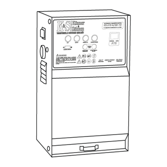
Page 5: General View Of The Ats Unit
GENERAL VIEW OF THE ATS UNIT The ATS unit consists of a housing that can be mounted on a wall. The ATS unit is connected to the generator set via a special control cable (included) and a power cable. The integrated clamping terminals are used to connect the generator output, redundant electrical devices and AC mains. -
Page 6: Operating The Ats Unit
OPERATING THE ATS UNIT The ATS unit automatically starts the generator and transfers load to it when the main power supply is disconnected. ATS unit has two modes: - Manual mode - Automatic mode MANUAL MODE If the ATS unit operates in manual mode, no mains voltage control is provided; the generator can only be controlled in manual mode. - Page 7 If the engine starts successfully, the engine operating indicator (10) and the generator power indicator (9) will glow steadily. After the engine starts successfully, the system will pause to warm up the engine before connecting the load. In summer mode the delay will be 10 seconds, in winter mode the delay will be 25 seconds. After this time, power switches will turn on and power consumers will be supplied by the generator.
-
Page 8: Connecting The Generator And Ats Unit To The Mains Supply
CONNECTING THE GENERATOR AND ATS UNIT TO THE MAINS SUPPLY Fig. 2 ATS CONTROL CABLE ATS UNIT MAINS SUPPLY GENERATOR ELECTRIC METER POWER CONSUMERS Fig. 3 8-pin ATS output on the generator panel 8-pin ATS output on the ATS unit Automatic start cable The ATS socket is located on the generator panel. -
Page 9: Electrical Diagram
ELECTRICAL DIAGRAM Diagram 2 Generator Mains Load www.ks-power.de/en | 8... -
Page 10: Maintenance
MAINTENANCE The device is energized, which is life threatening. Equipment maintenance must only be carried out by qualified personnel. During maintenance work, be sure to disconnect the PLEASE NOTE! mains and generator set to prevent inadvertent switching on of the ATS unit. Follow all instructions in the manual! The current list of service centers can be found on the exclusive importer’s website: www.ks-power.de. - Page 11 NOTES ________________________________________________ ________________________________________________ ________________________________________________ ________________________________________________ ________________________________________________ ________________________________________________ ________________________________________________ ________________________________________________ ________________________________________________ ________________________________________________ ________________________________________________ ________________________________________________ ________________________________________________ ________________________________________________ ________________________________________________ ________________________________________________ ________________________________________________ ________________________________________________ ________________________________________________ ________________________________________________ ________________________________________________ ________________________________________________ ________________________________________________ ________________________________________________ ________________________________________________ ________________________________________________ ________________________________________________ ________________________________________________ The current list of service centers can be found on the official importer’s website: www.ks-power.de www.ks-power.de/en | 10...
- Page 12 CONTACTS Germany ks-power.de info@dimaxgroup.de Poland ks-power.pl info.pl@dimaxgroup.de Ukraine ks-power.com.ua sales@ks-power.com.ua www.ks-power.de/en | 30...
Need help?
Do you have a question about the KS ATS 4/32 -12 and is the answer not in the manual?
Questions and answers