Table of Contents
Advertisement
Advertisement
Table of Contents

Related Manuals for Simmons SD200

Summary of Contents for Simmons SD200
- Page 1 OWNER’S MANUAL SimmonsDrums.net...
-
Page 2: Safety Instructions
OWNER’S MANUAL SAFETY INSTRUCTIONS THE LIGHTNING FLASH WITH ARROWHEAD SYMBOL WITHIN AN EQUILATERAL TRIANGLE IS INTENDED TO ALERT THE USER TO THE PRESENCE OF UNINSULATED DANGEROUS VOLTAGE WITHIN THE PRODUCT’S ENCLOSURE THAT MAY BE OF SUFFICIENT MAGNITUDE TO CONSTITUTE A RISK OF ELECTRIC SHOCK TO PERSONS. THE EXCLAMATION POINT WITHIN AN EQUILATERAL TRIANGLE IS INTENDED TO ALERT THE USER TO THE PRESENCE OF IMPORTANT OPERATING AND MAINTENANCE(SERVICING) INSTRUCTIONS IN THE LITERATURE ACCOMPANYING THE PRODUCT. APPARATUS SHALL NOT BE EXPOSED TO DRIPPING OR SPLASHING AND THAT NO OBJECTS FILLED WITH LIQUIDS, SUCH AS VASES, SHALL BE PLACED ON THE APPARATUS. Read these instructions. 12. Use only with the cart, stand, tripod, Keep these instructions. bracket, or table specified by the Heed all warnings. manufacturer, or sold with the Follow all instructions. -
Page 3: Table Of Contents
Connecting Headphones ......9 SD200 DRUM MODULE OPERATION Top Panel ..........10 LED Display . -
Page 4: Features
OWNER’S MANUAL FEATURES SD200 SOUND MODULE GENERAL FEATURES POLYPHONY • Voices - 32 SOUND • Drum Voices - 93 • Drum Kits - 10 Preset / 1 User • Songs - 10 Preset / 1 User EFFECTS • Reverb - Hall1, Hall2, Room1, Room2, Room3, Stage1, Stage2, Plate, Delay, Echo. -
Page 5: Assembling Your Kit
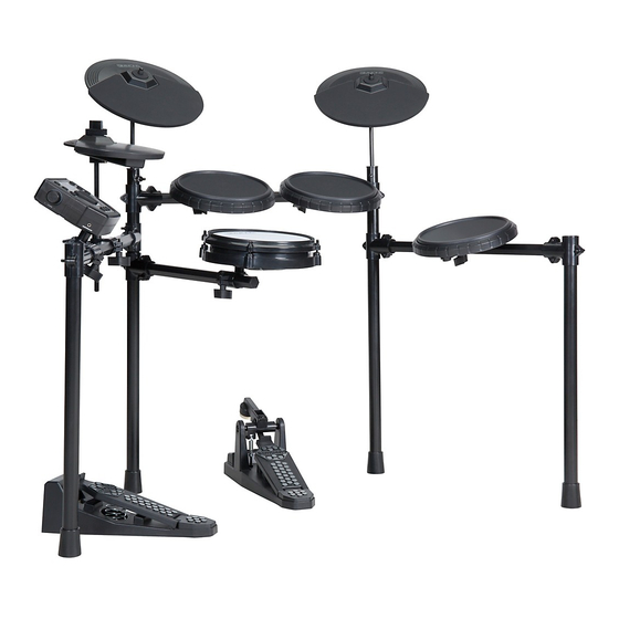
ASSEMBLING YOUR KIT INSIDE THIS PACKAGE Before assembly, please make sure that all the items listed below are present. Cymbals Accessories Single Zone Single Zone Single Zone AC Adaptor Multi-pin Cable Harness 10” Crash Cymbal Pad 10” Ride Cymbal Pad 8”... - Page 6 OWNER’S MANUAL ASSEMBLING YOUR KIT STEP 1 - DRUM RACK The Drum rack will be fully assembled in the box. Remove the drum rack from the box and tighten the connecting clamps until the kit is stable. STEP 2 - ATTACH CYMBAL ARMS Insert each cymbal arm into the rack clamp.
- Page 7 ASSEMBLING YOUR KIT STEP 5 - POSITION PEDALS & ATTACH DRUM PADS Place the hi-hat pedal on the floor and to the left, as illustrated below. Place the bass pedal on the floor in the center of the rack as illustrated. Loosen the wing screws on the drum mount clamps then place the tom pads into the mounts and tighten the wing screws.
-
Page 8: Connections
OWNER’S MANUAL CONNECTIONS CONNECTING THE PADS CAUTION! To prevent electric shock and damage to the device, make sure the power is switched OFF on the sound module and all related devices before making any connection. From Sound Module to 7 Pads Cymbal Pads To Crash To Ride... -
Page 9: Connecting The Power Supply
USB cable not included. CONNECTING HEADPHONES Your headphones can be connected to the SD200 module. The headphone jack is located on the front left side of module. Use the MASTER VOLUME knob to adjust the headphone volume. -
Page 10: Sd200 Drum Module Operation
OWNER’S MANUAL SD200 DRUM MODULE OPERATION TOP PANEL Volume Knob +/- Buttons Adjusts the current parameter on the screen Kit Button Switches the module to Kit Mode Rec/Play Button Plays the currently selected song, or records a Song Button user song... -
Page 11: Rear Panel
BACK PANEL AC Adapter Input Connection for the included 9V DC power adapter. USB Port Used for connecting the SD200 module to a computer. AUX Input Stereo 1/ 8 ” jack to connect external audio devices to module. Output ¼”... -
Page 12: Getting Started
OWNER’S MANUAL GETTING STARTED SWITCHING THE POWER ON 1. Connect the AC Adapter to the drum module. 2. Press the power switch on the front panel to turn on the module. NOTE: There is an automatic power off function that turns off the module when the kit is not being used for a certain period of time. -
Page 13: Selecting A Kit
GETTING STARTED SELECTING A KIT Entering KIT Mode 1. Press the [KIT] button. The LCD displays the current Kit number and the decimal point is in the first place as pictured to the right. 2. Press the [–] / [+] buttons to select a preset or user kit. SELECTING A SONG 1. -
Page 14: Advanced Operations
OWNER’S MANUAL ADVANCED OPERATIONS EDITING A KIT The drum kits of the module can be modified from the factory presets. However to save them you will have to store them to the User memory location. See the steps below on how to change the parameters for each pad input. -
Page 15: Click (Metronome)
ADVANCED OPERATIONS CLICK (METRONOME) The Click is the metronome. The click can be played during a song in song mode or on its own. Press [CLICK] button to start and stop the metronome. 1. To change the time signature, press and hold the [CLICK] button for 2 seconds 2. -
Page 16: Parameter Definitions
OWNER’S MANUAL ADVANCED OPERATIONS PARAMETER DEFINITIONS Retrig-C (Retrigger cancel) Retrigger Cancel prevents retriggering from occurring. Although setting this to a high value prevents retriggering, it then becomes easy for sounds to be omitted when the drums is played fast (like during a drum roll). -
Page 17: Drum Kit Presets
DRUM KIT PRESETS Preset Drum Kit List Drum Sound List Kit # Kit Name Section Number Sound Name Kit 1 Modern Maple Kick 22x18 Maple Kit 2 Acrylic Kick 22x18 Maple Rutes Kit 3 Grunge Kick 26x14 Acrylic Kit 4 Classic Rock Kick 24x16 Kick Tunnel... - Page 18 OWNER’S MANUAL DRUM KIT PRESETS Drum Sound List Drum Sound List Section Number Sound Name Section Number Sound Name 12" Gated Hi Hat HH Open Techno 18" 90s Rock Hi Hi Hat HH Closed HipHop 18" 90s Rock Low Hi Hat HH Foot HipHop 16"...
-
Page 19: Midi Implementation Chart
MIDI IMPLEMENTATION CHART O: YES X: NO Function Transmitted Recognized Remarks Basic Default 10 CH Only 1-16 CH Memorized Channel Changed 1-16 CH Mode Default Mode 3 Mode 3 Messages Altered ************** Note 0~127 0~127 Number: True voice ************** 0~127 Velocity Note ON O (99H, V=1–127) O (9nH, V=1–127) -
Page 20: Specifications
Two (2) Years limited warranty 1. Caution: Changes or modifications to this unit not expressly Subject to the limitations set forth below, Simmons® hereby approved by the party responsible for compliance could void the represents and warrants that the components of this product shall user’s authority to operate the equipment.
Need help?
Do you have a question about the SD200 and is the answer not in the manual?
Questions and answers