Table of Contents
Advertisement
Advertisement
Table of Contents

Related Manuals for Pentair Pentek Intellidrive Series


Summary of Contents for Pentair Pentek Intellidrive Series
-
Page 2: Safety
Safety Important Safety Instructions Risk of fire. Can cause severe injury, property damage or death if installed with incorrect SAVE THESE INSTRUCTIONS - This manual or inadequate circuit breaker protection. To ensure contains important instructions that should be protection in the event of an internal fault in the followed during installation, operation, and PENTEK INTELLIDRIVE, install the Drive on an maintenance of the PENTEK INTELLIDRIVE Variable... -
Page 3: Table Of Contents
Table of Contents Safety . . . . . . . . . . . . . . . . . . . . . . . . . . . . . . . . . . . . . . . . . . . . . . . . . . . . . . . . . . . . . 2 Owner’s Information . -
Page 4: Description
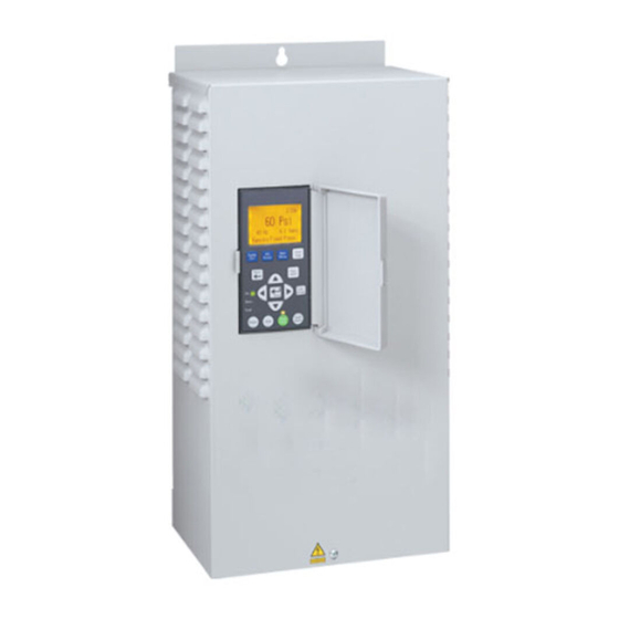
Description Specifications/Ratings pump Owner’s Manual and the National Electrical Code for proper wire size. Input Voltage ... 1-Phase 230VAC Nominal (190–265VAC) Input Frequency ............50/60Hz Each carton contains: Ambient Temperate Range .... -4 to 122 °F (-20° to 50 °C) • Variable Frequency Drive PENTEK INTELLIDRIVE Output Connections ....3-Phase, 3-Wire/1-Phase or • Pressure Transducer 1-Phase/2-Wire... - Page 5 Description Transducer Keypad The PENTEK INTELLIDRIVE uses a 4-20mA, The keypad programs the Drive, monitors the status 0-100PSI pressure transducer to control motor of the pump, and displays faults if they occur. speed (Drive settings may be changed to use a Each button has a unique function, as described in max 300 PSI transducer).
-
Page 6: Installation
Installation Table 2 - Circuit breaker and wire sizes (Typical installation with 400’ cable length from service entrance to drive) Input Wire Motor Volts Motor HP Circuit Breaker* Generator (kVA)** Size 2-wire 1-1/2 3-wire 1-1/2 3 phase 1-1/2 12.6 * With properly-sized circuit breakers, the Drive is protected from short circuit on the input and the output. There is no risk of fire or electrical shock due to a short circuit. - Page 7 Installation Mounting the Drive Ensure the Drive’s ventilation holes are not blocked and there is enough space around it To mount the Drive as shown in Figure 6, follow to allow free air flow (minimum 3” clearance this procedure: on top, bottom, and sides). See Figure 6. Once First, remove the cover by backing out screw the Drive is mounted, electrical wiring can be at bottom of front cover.
- Page 8 Installation Wiring to connect all output wires (larger wire gauge) first, then all input wires. To allow for ease of wiring, the enclosure wiring Pump Connections area is free of electronics other than the terminals. Conduit holes and knockouts are located so If the PENTEK INTELLIDRIVE is used with above that the wire can be fed straight through to the ground motors (3-phase only) not rated for Variable...
- Page 9 Installation Pressure Tank Recommendations To connect the transducer wires: 1. Strip wire ½ inch Minimum tank size is two gallons. Use a pre- charged pressure tank with Drive, as shown in 2. Push spring terminal up with finger or slotted Table 3. The tank size must equal at least 20 screwdriver percent of the pump’s rated flow in gallons per 3.
-
Page 10: Initial Startup
Initial Startup Initial Startup and Service Factor Amps Programming Procedures To maximize pump performance, be sure to enter the correct Service Factor Amps (SF Amps) Ensure that the cover is installed before operating in the PENTEK INTELLIDRIVE. the PENTEK INTELLIDRIVE. • Entering SF Amps higher than the motor rating Most installations will only require the initial lets the Drive supply more amps to the motor... - Page 11 Initial Startup Table 4 - Pentek Motor Service Factor Amps discharge runs clear, then press STOP button to stop Drive. Rating @ Service Motor PENTEK Part Risk of explosion. In Pump Out 230V Factor Type Number mode, pump runs at a constant speed, which can Amps cause very high pressure if flow is restricted.
-
Page 12: Programming
Programming 60 Hz to 80 Hz Operation There are three ways to change the pressure setpoint: When installing the PENTEK INTELLIDRIVE with While running the pump a motor and liquid end of the same HP rating, operate it at 60 Hz (the default value). The Drive •... - Page 13 Programming Table 5 lists all available commands and parameters for the PENTEK INTELLIDRIVE. Table 5 - Main Menu and Parameters Value Menu Unit of Description Parameter Settings Measure Default Min. Max. Hour Format Hours 12Hr 12Hr 24Hr Selects 12 or 24 hour time scale. Sets current time.
- Page 14 Programming Table 5 - Continued Value Menu Unit of Parameter Description Settings Measure Default Main pressure setpoint used. Sets Max main system operational pressure. Sensor Internal This parameter is accessed here, 60 PSI 15 PSI Value Setpoint through PSI Preset button, or by minus 3 pressing Enter button while in PSI.
- Page 15 Programming Table 5 - Continued Value Menu or Parameter Unit of Measure Description Sub Menu Default Excessive Enables or disables Excessive Runtime Runtime Disabled Disabled Enabled Detection. Detection Ex Runtime Excessive Number of hours Drive can run before it Hours Runtime Hours faults on Excessive Runtime.
-
Page 16: I/O Connections
I/O Connections The I/O terminals are located in the center of the wiring compartment, as shown previously in Figure 9. The Digital Input connections (I1 and I2) are used to control the Drive based on the state of an external device, such as a flow switch, moisture sensor, alternator, or other device. - Page 17 I/O Connections Table 6 - I/O Function, Connections, Ratings Label Function Connection Rating Positive connection for transducer Red transducer wire 24 Volt (supplied) Negative connection for transducer Black transducer wire Positive side of 24V external device, i.e., Positive side of 24 volt power supply. flow switch, moisture sensor, alternator, Used to power external devices.
-
Page 18: Additional Information
Additional Information RS-485 Communications Table 7 - Service Factor Amps @ 230V RS-485 is a US-based telecommunications Service Factor Rating, standard for binary serial communications between in Amps Motor Type devices. It is the protocol, or set of specifications, CentriPro¹ Franklin²... -
Page 19: Troubleshooting
Troubleshooting* Fault Possible Causes Solution Shorted output Check for any shorts in motor cables. Over Current Damaged wire insulation Check motor wire insulation with a megger. With power to Drive off, measure outputs Internal Drive short with ohmmeter to detect short. Over Voltage Check for a generator or switching on input Power cycling on and off... - Page 20 Troubleshooting Troubleshooting, continued Fault Possible Causes Solution Check all transducer wires are securely Intermittent connection connected or for damaged cable insulation. Check for proper wiring of all transducer Open Connection wires and verify cable connector securely attached to transducer. Open Transducer Drive cannot read transducer Check electrical system for ground loops or signal...
- Page 21 Troubleshooting Troubleshooting, continued Warning Possible Causes Solution Verify ground wire is connected on both incoming voltage side and motor side of Drive. With the power disconnected, use an Ungrounded Drive, with ohmmeter to verify which pipe the Drive’s ground detection parameter Warning LED flashing transducer is connected to.
-
Page 22: Software Updates
Software Updates NOTE: If using the information at www.sta-rite.com/PIDupdate, please note that some internet browsers need to be refreshed to show the most current software files. Please press Ctrl+F5 to refresh the webpage to verify that it is displaying the latest data. To determine whether you need to update, compare the software version number in your Pentek Intellidrive against the software you plan to install. -
Page 23: Warranty
F o r mo r e i n f o r ma t i o n , c o n t a c t y o u r l o c a l d i s t r i b u t o r . 2 3 1 8 4 F r a s e r H w y .
Need help?
Do you have a question about the Pentek Intellidrive Series and is the answer not in the manual?
Questions and answers