Table of Contents
Advertisement
Quick Links
Advertisement
Table of Contents

Subscribe to Our Youtube Channel
Related Manuals for MiX Telematics Talk


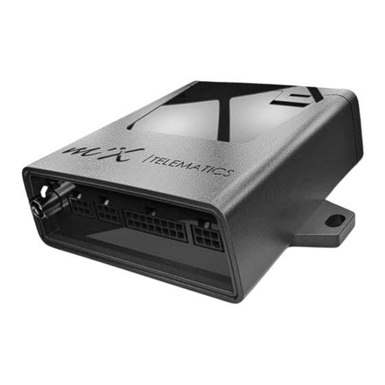
Summary of Contents for MiX Telematics Talk
- Page 1 MiX Talk Installation Guide...
-
Page 2: Table Of Contents
Table of Contents Introduction ............................... 3 Glossary Terms ..........................4 Hardware Features ..........................4 Product Parts and Spare Parts ......................5 Power Requirements ......................... 7 Safety Precautions............................ 7 Prior to Installation ............................ 7 Preparing the SIM card ........................7 Inserting of SIM card ......................... 7 Configuration of unit .......................... -
Page 3: Introduction
The MiX Talk unit supports fixed dialling and fixed incoming call numbers for easy administrative management. The MiX Talk unit can be directly setup and configured via a serial data cable connected to either a Laptop or PC. The unit can also be configured remotely via SMS. The MiX Talk Unit does not support any continuous GSM data transmission. -
Page 4: Glossary Terms
Auto Answer a predefined number of rings. The number of rings is also configurable. The MiX Talk unit can be directly setup and configured via a serial (RS- Direct and/or Remote 232) data cable connected either to a Laptop or PC. Direct setup and Configuration configuration can also be done remotely via SMS. -
Page 5: Product Parts And Spare Parts
Auxiliary Output The auxiliary output can be connected directly to an in-cabin radio An open collector output from the MiX Talk unit gives it the ability to Radio Mute Function automatically Mute / Un-mute an in-cabin radio for incoming and outgoing calls The unit displays it’s ON or OFF power status with a dedicated LED on... - Page 6 MiX Talk Main Harness Hands Free Speaker Key Pad & Harness MiX Talk Electronic Unit External GSM Antenna Hands Free Microphone P a g e...
-
Page 7: Power Requirements
Before inserting the SIM card ensure that the SIM is configured as follows “No PIN Required” In this case the MiX Talk units will not take any action. It will leave the SIM in the “No PIN Required” configuration. -
Page 8: Sms Configuration
The configuration of a unit when it is connected to a PC or laptop via a serial cable is described in Appendix D. Mix Fleet Manager MiX Talk is NOT integrated with MiX Fleet Manager Configuration of telephone numbers are only possible via: 1. SMS commands from a standard Cellphone 2. -
Page 9: Installation
None Configuration Utility Configure the unit using the PC Configuration Utility (Separate user guide) Install the MiX Talk main harness and connect to the vehicle’s power. None Install the MiX Talk electronic unit None Install the MiX Talk speaker, microphone and antenna... -
Page 10: General Wiring Requirements
General Wiring Requirements Note the product’s wire gauge cross-sectional area. If the wire gauge cross-section is reduced, current density increases which may cause the wiring to overheat. Cables should be routed in existing channels and should not be routed parallel to ignition cables or other cables subject to high current. -
Page 11: Harnesses And Connectors
Avoid Recommended Avoid sharp corners and bends: Use rounded bends: Avoid coupling between 2 different pieces of wire: Separate coiled wires where possible: Harnesses and connectors Please read section 10 (Safety) of this document before installing the vehicle harness. Confirm which of the harnesses will be used in the install as the wire colours will differ depending on the harness selected. - Page 12 Antenna Connector AUX – Not Connected Serial Data – Not Speaker Connector Connected Microphone Connector MiX Talk Main Harness Main Harness / Key Pad Conectors 12 | P a g e...
- Page 13 The FM Voice Kit Microphone (440FT0204) connects to the 2 way connector on the front panel. See image above. 4.5.5 Serial Data Configuration Port When using the MiX Talk Serial Harness SR2 (440FT0315) during configuration it si connected to the 3 way connector on the front panel. See image above. 4.5.6 Audio Line-Output MiX Talk Line Out Harness AX4 (440FT0319) A dedicated Radio Audio Line Interface cable is available as an optional extra that can be connected to the vehicle radio if required.
-
Page 14: Wiring And Connections
Wiring and Connections 4.6.1 Positioning the Product in the vehicle Note: Please follow the instructions, regarding the positioning of product components, as contained in the “Safety” section, of this document, section 10. The Product must be installed inside the passenger compartment or the driver cabin, to protect it from possible damage by water, solvents, fuel or other environmental factors. -
Page 15: General Operation
General Operation Keypad Functions Figure 1 Keypad LED’s 6.1.1 Refer to Figure 1: Answer incoming call with any of the four buttons Terminate call with the “On hook” button Status LED will indicate missed calls from pre-configured numbers ... -
Page 16: Troubleshooting
Troubleshooting Supporting Documentation can be found at: https://confluence.mixtelematics.com/display/MFHF/MiX+Talk+-+Home+Page Symptom Probable Cause Action Unit does not Check the voltage supply to the Product No battery voltage applied to switch ON (LED Ensure the connectors are properly fitted Product. does not flash) Check fuse if applicable Refer to section 3.1 for the correct SIM card... -
Page 17: Appendix A: Safety
Installers should not smoke or make use of naked flames, which could cause a fire in or near the vehicle. After installation, verify that no interference is caused to the vehicle’s electrical system. Check dashboard warning lights and error messages. Should any error conditions exist, remove the installed unit and contact MiX Telematics for assistance. 10.1.1 Tools ... -
Page 18: Appendix B: Configurable Parameters
11.5.1 Summary: The four Button Numbers (BUT) are exclusively used for voice calls. The MiX Talk unit can dial any of four telephone numbers configured as a Button Number. Thus for example if the operator presses button number one then the unit will dial the telephone number configured and associated with button number one. -
Page 19: Incoming Call Number
The Call Length Timer is used to limit the length in time of voice calls. Once the timer reaches zero the MiX Talk unit responds with four beeps to warn the operator that is about to cut the call. The operator then needs to press any button except the “On Hook”... -
Page 20: Auto Answer Timer
11.12 Auto Answer Timer 11.12.1 Summary: The Auto Answer Timer is used to determine when the unit should automatically answer an incoming call. When the unit receives an incoming call the Auto Answer Timer is activated. If the Auto Answer Timer reaches zero before the call is answered by the operator, then the unit will automatically answer the call. -
Page 21: Appendix C: Configuration Via Sms Message
Parameter Format Example Restrictions Initiator Number On first power-up the Existing Master MASTER will be set to the MiX Talk Device MASTER +27836750000 Number default of 10 zeros. New Command MASTER;+27836750000;+27836750001 Master Number and Cell Set Master number used to send SMS... - Page 22 Parameter Category Destination Message ID Parameter Format Example Restrictions Initiator Number Config Number MiX Talk Device CONF One numerical digit Cell number used to send Indicator Command CONF;1;+27836750002 SMS = Master or Config Number Allocated Number +27836750002 SMS Sender and...
- Page 23 Set Low Power Timer Low Power Timer in SMS Sender and Master Three numerical digits Seconds 60, 120, Reply from applicable MiX Talk Reply LP;120;OK Device Confirmation Call Length Timer 600, 900, Cell number used to send SMS = Command...
- Page 24 Answer Timer Auto Answer Timer SMS Sender and Master Two numerical digits in Seconds 0, 5, 10, 15, AA;15;OK Reply from applicable MiX Talk Reply AA;0;OK Device Confirmation Cell number used to send SMS = Command MiX Talk Device OPEN...
- Page 25 SMS = Master or Config Device Number Number Master or Existing Master QUERY +27836750000 Config Number Reply QUERY;MASTER;+27836750000;OK Applicable MiX Talk Device Confirmation Cell number used to send MiX Talk Query Config Command QUERY CONF QUERY;CONF SMS = Master or Config Device Numbers...
- Page 26 Message ID Parameter Format Example Restrictions Initiator Number Cell number used Query Incoming to send SMS = Command MiX Talk Device QUERY QUERY;PH Call Numbers Master or Config Number Incoming Call Master or Config QUERY +27836750009 Number 1 Incoming Call...
- Page 27 Low Power Timer Config Low Power Timer Value Call Length Timer Call Length 1200 Timer Value Call Continue Timer Call Continue Applicable MiX Talk Reply QUERY;TIMER;LP;120;CT;1200;PB;10;RT;120;AA;10;OK Timer Value Device Incoming Ring Timer Incoming Ring Timer Value Auto Answer Timer Auto Answer...
-
Page 28: Appendix D: Configuration Via Pc/Laptop Application
6. Wait for unit start up confirmation – (Buzzer beep – speaker tone – buzzer beep – speaker tone) 7. Connect Serial Harness - 3-way connector 8. Open the MiX Talk Configuration application The following Screen will appear: 1. Select the correct Com Port from the drop down box below the Serial Configuration heading 2. - Page 29 See example below: 29 | P a g e...
- Page 30 Click on the Firmware Configuration tab The following screen will appear All the configuration items as set out in Appendix B can now be changed as required. See the examples of the application’s visual feedback below. 30 | P a g e...
- Page 31 31 | P a g e...
- Page 32 Load Config and save Config is not used at present 32 | P a g e...
Need help?
Do you have a question about the Talk and is the answer not in the manual?
Questions and answers