Table of Contents
Advertisement
Quick Links
Basic series
ﺍﻟﻣﺟﻣﻭﻋﺔ ﺍﻷﺳﺎﺳﻳﺔ
Remote control
series
ﻣﺟﻣﻭﻋﺔ ﺍﻟﺗﺣﻛﻡ ﻋﻥ ﺑﻌﺩ
Sensor series
ﻣﺟﻣﻭﻋﺔ ﺃﺟﻬﺯﺓ
ﺍﻻﺳﺗﺷﻌﺎﺭ
READ AND SAVE THESE OPERATION INSTRUCTION.
Thank you very much for choosing KDK Air Curtain.
Please read these instructions carefully before attempting to install,
operate or service the KDK Air Curtain.
Failure to comply with instructions could result in personal injury or
prorerty damage. Please explain to users how to operate and maintain
the product after installation, and this booklet should be presented to users.
Please retain this booklet for future reference.
(Containing the Installation Instruction)
3009UA
4009UA
3009GA
4009GA
3009DA
4009DA
.ﻋﺩﻡ ﺍﻻﻣﺗﺛﺎﻝ ﻟﻠﺗﻌﻠﻳﻣﺎﺕ ﻳﻣﻛﻥ ﺃﻥ ﻳﺅﺩﻱ ﺇﻟﻰ ﺣﺩﻭﺙ ﺇﺻﺎﺑﺎﺕ ﺃﻭ ﺃﺿﺭﺍﺭ ﻓﻲ ﺍﻟﻣﻣﺗﻠﻛﺎﺕ
.ﻳﺭﺟﻰ ﺍﻟﺷﺭﺡ ﻟﻠﻣﺳﺗﺧﺩﻣﻳﻥ ﻛﻳﻔﻳﺔ ﺗﺷﻐﻳﻝ ﻭﺻﻳﺎﻧﺔ ﺍﻟﻣﻧﺗﺞ ﺑﻌﺩ ﺍﻟﺗﺛﺑﻳﺕ، ﻭﻳﻧﺑﻐﻲ ﺃﻥ ﻳﻘ ﺩ ّ ﻡ ﻫﺫﺍ ﺍﻟﻛﺗﻳﺏ ﻟﻠﻣﺳﺗﺧﺩﻣﻳﻥ
Operation Instruction
3012UA
3015UA
4012UA
4015UA
3012GA
3015GA
4012GA
4015GA
3012DA
3015DA
4012DA
4015DA
." KDK" ﺷﻛﺭﺍ ﺟﺯﻳﻼ ﻟﻙ ﻋﻠﻰ ﺍﺧﺗﻳﺎﺭ "ﺳﺗﺎﺭﺓ ﺍﻟﻬﻭﺍء ﻣﻥ
.ﺍﻟﺭﺟﺎء ﻗﺭﺍءﺓ ﻫﺫﻩ ﺍﻟﺗﻌﻠﻳﻣﺎﺕ ﺑﻌﻧﺎﻳﺔ ﻗﺑﻝ ﺍﻟﻘﻳﺎﻡ ﺑﺎﻟﺗﺛﺑﻳﺕ
."KDK" ﺗﺷﻐﻳﻝ ﺃﻭ ﺻﻳﺎﻧﺔ ﺧﺩﻣﺔ "ﺳﺗﺎﺭﺓ ﺍﻟﻬﻭﺍء ﻣﻥ
.ﺍﻟﺭﺟﺎء ﺍﻟﺣﻔﺎﻅ ﻋﻠﻰ ﻫﺫﺍ ﺍﻟﻛﺗﻳﺏ ﻟﻠﺭﺟﻭﻉ ﺇﻟﻳﻪ ﻓﻲ ﺍﻟﻣﺳﺗﻘﺑﻝ
ﺗﻌﻠﻳﻣﺎﺕ ﺍﻟﺗﺷﻐﻳﻝ
ﻳﺣﺗﻭﻱ ﻋﻠﻰ ﺗﻌﻠﻳﻣﺎﺕ ﺍﻟﺗﺛﺑﻳﺕ
Air Curtain
ﺳﺗﺎﺭﺓ ﺍﻟﻬﻭﺍء
Model No.
:ﻣﻭﺩﻳﻝ ﺭﻗﻡ
.ﺍﻗﺭﺃ ﻭﺍﺣﻔﻅ ﺗﻌﻠﻳﻣﺎﺕ ﺍﻟﺗﺷﻐﻳﻝ ﻫﺫﻩ
Advertisement
Table of Contents

Subscribe to Our Youtube Channel
Related Manuals for KDK Basic Series


Summary of Contents for KDK Basic Series
- Page 1 Please retain this booklet for future reference. .ﺍﻗﺭﺃ ﻭﺍﺣﻔﻅ ﺗﻌﻠﻳﻣﺎﺕ ﺍﻟﺗﺷﻐﻳﻝ ﻫﺫﻩ ." KDK" ﺷﻛﺭﺍ ﺟﺯﻳﻼ ﻟﻙ ﻋﻠﻰ ﺍﺧﺗﻳﺎﺭ "ﺳﺗﺎﺭﺓ ﺍﻟﻬﻭﺍء ﻣﻥ .ﺍﻟﺭﺟﺎء ﻗﺭﺍءﺓ ﻫﺫﻩ ﺍﻟﺗﻌﻠﻳﻣﺎﺕ ﺑﻌﻧﺎﻳﺔ ﻗﺑﻝ ﺍﻟﻘﻳﺎﻡ ﺑﺎﻟﺗﺛﺑﻳﺕ ."KDK" ﺗﺷﻐﻳﻝ ﺃﻭ ﺻﻳﺎﻧﺔ ﺧﺩﻣﺔ "ﺳﺗﺎﺭﺓ ﺍﻟﻬﻭﺍء ﻣﻥ...
-
Page 2: Table Of Contents
Contents Safety instructions ................2 Installation cautions ..............3 ~ 4 Supplied accessories ................. 5 Parts name and dimensions ............5 ~ 6 Requirement of installation ............... 7 How to install ................8 ~ 10 Multiple products operation in group ..........11 Wiring diagram ................ -
Page 3: Safety Instructions
Safety instructions Please observes strictly ■ If the supply cord is damaged, it must be replaced by the manufacturer, its service agent or similarly qualified persons in order to avoid a hazard. ■ This product is not intended for use by persons (including children) with reduced physical, sensory or mental capabilities, or lack of experiences and knowledge, unless they have been given supervision or instruction concerning use of the product by a person responsible... -
Page 4: Installation Cautions
Installation cautions WARNING ■A over load protection device must be ■It’s prohibited to install any other installed in the wiring when installing. substances with magnetic among the diameter of 20m from gate magnetic switch for sensor series. May cause fire or It may result in fault or error electric shocks. - Page 5 Installation cautions WARNING ■It’s prohibited to install in the following locations. Locations such as bathroom Location with Outdoor or locations that where it will produce combustible gas or could be sprayed by water. excessive humidity or vapor emission of exhaust with high humidity.
-
Page 6: Supplied Accessories
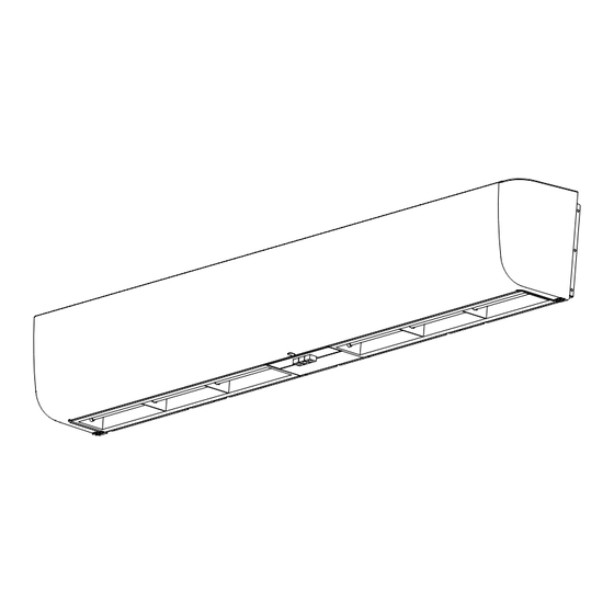
Gate magnetic Screw ⑤ ⑩ switch Parts name and dimensions ■Front view of basic series ■Right view of basic series Direction ■Back view of basic series Power supply cord Six holes (M8 bolts) Air outlet Eight holes (8mm wood screw) ■Front view of remote control series... - Page 7 ■Back view of sensor series Air outlet Power supply cord Six holes (M8 bolts) Eight holes (8mm wood screw) Model No. 3009UA , 4009UA Basic series 1200 3012UA , 4012UA 1500 3015UA , 4015UA 3009GA , 4009GA Remote control series 1200...
-
Page 8: Requirement Of Installation
Requirement of installation ■It’s prohibited to install in the following locations. Locations with temperature It’s prohibited to install in the uneven exceeding 40℃ or less than -10℃. surface.(Flatness shall be 3mm below.) 40℃ Distortion results in reducing the separation performance. Locations where freezing could happen. -
Page 9: How To Install
How to install 1.Fix the mounting plate ■Mounting on concrete wall. 1.Remove mounting plate from product. Taking the mounting plate by removing the screws. 2.Firmly fix the bolts in the proper position. ·Determine the position on the wall and drill into the wall. Mounting plate Screw ·Fit the bolts into the holes. - Page 10 How to install 2.Preparation before wiring Pre-hang up the product 150mm above into the hook of mounting plate. Hook ※Carry out this step if the distance between top face of product and ceiling is less than 150mm. 3.Wiring WARNING ■Connect the power cord to the power supply line according to the wiring diagram and the local electrical wiring rules of fixed wiring.
- Page 11 How to install 4.Installation of product CAUTION 1.Place the product on the mounting plate. ■Product should be installed by 2 persons. Otherwise, the product may fall down and it may cause injuries. 2.Adjust the position of the product. Align the groove of back panel with both sides of mounting plate.
-
Page 12: Multiple Products Operation In Group
■The number of interlocking operation is not more than 6. ●Please purchase necessary parts following with local electrical requirements. Wiring diagram ■Please follow with below figures to conduct the wiring. ■Basic series Capacitor Orange Green/Yellow Black... -
Page 13: Operation Methods
Operation methods Operation of Control panel ■Basic series ■Sensor series 4009UA ※Representative model HIGH Start to operate Press “HI”or“LO” button to start the product as shown in left figure. Select the mode of operation Press “HI” button if high air velocity is required. - Page 14 Operation methods Operation of Control panel Operation of Remote control Remote control series STAND-BY Signal light for low operation Signal receiver HIGH 3009GA ※Representative model Signal light for high operation NOTE The button in control panel can be operated for emergency in case if remote control is not avaliable.
- Page 15 Operation methods Operation of remote control Please hold the remote control toward the signal receiver and use it within 5m from the signal receiver at angle of 30° as shown below. Signal transmitter Signal receiver NOTE The remote control should be used with product in same room.
- Page 16 Operation methods ■Guide vane in air outlet can be adjusted according to service environment to reach the ideal separation performance. While Strong wind in outdoor Guide vane Strong wind Air outlet in outdoor While light wind in outdoor Guide vane light wind Air outlet in outdoor...
-
Page 17: Routine Maintenance
Routine maintenance WARNING ■Before touching this product, ensure ■Be sure to uninstall the product if it that the power switch connected to will not be used any longer. this product is turned off. The product may fall off. This may result in electric shock. - Page 18 Routine maintenance CAUTION ■If the supply cord is damaged, it must ■Two persons are required be replaced by manufacturer, its to conduct the maintenance. service agent or similarly qualified persons in order to avoid a Otherwise product may drop hazard. results in injuries.
- Page 19 Routine maintenance To safely use the product in a long time, please follow these items below. 1)Note that all screws don’t work loose. It tends to cause vibration, dropping or a fire. 2)Motor is intended to use for about 20000 hours. But the actual life of motor may vary depending on service environment.
-
Page 20: Trouble Shooting Guide
Trouble shooting guide Firstly check the following items, if malfunction still can’t be solved, please disconnect from supply mains and contact with distributor and repair shop. Condition 1st Possible reason 2nd Possible reason 3rd Possible reason Can't operate. Check the voltage. Wiring is not correct. -
Page 21: Specification
Specification Voltage: 1 phase 220V Frequency: 50Hz Outlet Power Current Air Volume Noise Installation Velocity Consumption Insulation Length Weight m³/h dB(A) Model height Class (m) High Low High Low High Low High Low High Low 3009UA 3009DA 3009GA 10.5 8.5 76 0.35 0.32 1100 920 48.5 45 12.5... -
Page 22: ﺗﻌﻠﻳﻣﺎﺕ ﺍﻟﺳﻼﻣﺔ
ﺗﻌﻠﻳﻣﺎﺕ ﺍﻟﺳﻼﻣﺔ ﺍﻟﺭﺟﺎء ﺍﻟﻣﻼﺣﻅﺔ ﺑﺩﻗﺔ .ﺇﺫﺍ ﻛﺎﻥ ﻛﺎﺑﻝ ﺍﻟﺗﺯﻭﻳﺩ ﺑﺎﻟﻁﺎﻗﺔ ﺗﺎﻟﻑ، ﻓﻳﺟﺏ ﺍﺳﺗﺑﺩﺍﻟﻪ ﻣﻥ ﻗﺑﻝ ﺍﻟﻣﺻﻧﻊ ﺃﻭ ﻣﺭﻛﺯ ﺍﻟﺧﺩﻣﺔ ﺍﻟﺗﺎﺑﻊ ﻟﻪ ﺃﻭ ﻓﻧﻲ ﻣﺅﻫﻝ ﻟﺗﺟﻧﺏ ﺍﻟﻣﺧﺎﻁﺭ ﻫﺫﺍ ﺍﻟﻣﻧﺗﺞ ﻏﻳﺭ ﻣﺧﺻﺹ ﻟﻼﺳﺗﺧﺩﺍﻡ ﻣﻥ ﻗﺑﻝ ﺍﻷﺷﺧﺎﺹ )ﺑﻣﺎ ﻓﻲ ﺫﻟﻙ ﺍﻷﻁﻔﺎﻝ( ﺍﻟﺫﻳﻥ ﻳﻌﺎﻧﻭﻥ ﻣﻥ ﻧﻘﺹ ﻓﻲ ﺍﻟﻘﺩﺭﺍﺕ ﺍﻟﺑﺩﻧﻳﺔ ﻭﺍﻟﺣﺳﻳﺔ... - Page 23 ﺗﻧﺑﻳﻬﺎﺕ ﺍﻟﺗﺛﺑﻳﺕ ﺗﺣﺫﻳﺭ ﻳﺣﻅﺭ ﺗﺛﺑﻳﺕ ﺍﻟﻣﻧﺗﺞ ﻓﻲ ﻣﻭﺍﻗﻊ ﻣﺛﻝ ﻣﻭﺍﻗﻊ ﺍﻵﻻﺕ، ﻭﺍﻟﻣﺻﺎﻧﻊ ﺍﺳﺗﺧﺩﺍﻡ ﺑﺭﺍﻏﻲ ﺑﺎﻟﻛﻣﻳﺔ ﺍﻟﻣﺣﺩﺩﺓ ﻭﺍﻟﻘﻁﺭ ﺍﻟﻣﺣﺩﺩ ﻟﻠﺭﺑﻁ .ﺑﻬﻡ ﺃﺛﻧﺎء ﺗﻌﻠﻳﻕ ﺍﻟﻣﻧﺗﺞ ﺍﻟﻛﻳﻣﻳﺎﺋﻳﺔ ﺃﻭ ﻣﺭﺍﻓﻕ ﺍﻟﺑﺣﻭﺙ ﺣﻳﺙ ﺃﻧﻪ ﺳﻳﺗﻌﺭﺽ ﻟﻠﻐﺎﺯﺍﺕ ﺍﻟﺳﺎﻣﺔ ﺍﻟﺗﻲ ﺗﺣﺗﻭﻱ ﻋﻠﻰ ﺍﻷﺣﻣﺎﺽ ﻭﺍﻟﻘﻠﻭﻳﺎﺕ، ﻭﺍﻟﻣﺫﻳﺑﺎﺕ ﺍﻟﻌﺿﻭﻳﺔ، ﻭﺃﺑﺧﺭﺓ ﺍﻟﻁﻼء، ﻭﻏﻳﺭﻫﺎ، ﻭﻟﻠﻐﺎﺯﺍﺕ ﺍﻟﺗﻲ ﺗﺣﺗﻭﻱ .ﻭﺇﻻ...
-
Page 24: ﺍﻹﻛﺳﺳﻭﺍﺭﺍﺕ ﺍﻟﻣﻠﺣﻘﺔ
ﺍﻹﻛﺳﺳﻭﺍﺭﺍﺕ ﺍﻟﻣﻠﺣﻘﺔ ﻳﺗﻡ ﺗﻭﻓﻳﺭ ﺍﻹﻛﺳﺳﻭﺍﺭﺍﺕ ﺍﻟﺗﺎﻟﻳﺔ ﻣﻊ ﺳﺗﺎﺭﺓ ﺍﻟﻬﻭﺍء ﻓﻲ ﺍﻟﻌﺑﻭﺓ. ﻋﻧﺩ ﻓﺗﺢ ﺍﻟﻌﺑﻭﺓ، ﺗﺣﻘﻕ ﻣﻣﺎ ﺇﺫﺍ ﻛﺎﻧﺕ ﻛﻝ ﺍﻹﻛﺳﺳﻭﺍﺭﺍﺕ ﻣﻭﺟﻭﺩﺓ. ﻓﻲ ﺣﺎﻟﺔ ﻓﻘﺩﺍﻥ ﺃﻱ ﻣﻥ .ﺍﻹﻛﺳﺳﻭﺍﺭﺍﺕ، ﻓﺎﻟﺭﺟﺎء ﺍﻻﺗﺻﺎﻝ ﺑﺎﻟﻣﻭﺯﻉ ﺍﻟﻛﻣﻳﺔ ﺍﻟﻛﻣﻳﺔ ﻣﺟﻣﻭﻋﺔ ﺃﺟﻬﺯﺓ ﻣﺟﻣﻭﻋﺔ ﺍﻟﻣﺟﻣﻭﻋﺔ ﺍﻻﺳﻡ ﺍﻟﺷﻛﻝ .ﺭﻗﻡ ﻣﺟﻣﻭﻋﺔ ﺃﺟﻬﺯﺓ ﻣﺟﻣﻭﻋﺔ... - Page 25 ﺍﻹﻛﺳﺳﻭﺍﺭﺍﺕ ﺍﻟﻣﻠﺣﻘﺔ ﺍﻟﻣﻧﻅﺭ ﺍﻷﻳﻣﻥ ﻟﻣﺟﻣﻭﻋﺔ ﺃﺟﻬﺯﺓ ﺍﻻﺳﺗﺷﻌﺎﺭ ﺍﻟﻣﻧﻅﺭ ﺃﻣﺎﻣﻲ ﻟﻣﺟﻣﻭﻋﺔ ﺃﺟﻬﺯﺓ ﺍﻻﺳﺗﺷﻌﺎﺭ ﺍﻟﻣﻧﻅﺭ ﺍﻟﺧﻠﻔﻲ ﻟﻣﺟﻣﻭﻋﺔ ﺃﺟﻬﺯﺓ ﺍﻻﺳﺗﺷﻌﺎﺭ ﺍﺗﺟﺎﻩ ﻣﺧﺭﺝ ﺍﻟﻬﻭﺍء (M8 ﺳﺗﺔ ﺛﻘﻭﺏ )ﺃﺷﺭﻁﺔ ﻛﺎﺑﻝ ﺍﻟﻁﺎﻗﺔ (ﺛﻣﺎﻧﻳﺔ ﺛﻘﻭﺏ )ﺑﺭﻏﻲ ﺧﺷﺏ 8 ﻣﻡ .ﻣﻭﺩﻳﻝ ﺭﻗﻡ 3009UA, 4009UA 1200 3012UA, 4012UA ﺍﻟﻣﺟﻣﻭﻋﺔ ﺍﻷﺳﺎﺳﻳﺔ 1500 3015UA, 4015UA 3009GA, 4009GA...
-
Page 26: ﻣﺗﻁﻠﺑﺎﺕ ﺍﻟﺗﺛﺑﻳﺕ
ﻣﺗﻁﻠﺑﺎﺕ ﺍﻟﺗﺛﺑﻳﺕ .ﻳﺣﻅﺭ ﺍﻟﺗﺛﺑﻳﺕ ﻓﻲ ﺍﻟﻣﻭﺍﻗﻊ ﺍﻟﺗﺎﻟﻳﺔ .ﻳﺣﻅﺭ ﺍﻟﺗﺛﺑﻳﺕ ﻋﻠﻰ ﺍﻟﺳﻁﺢ ﻏﻳﺭ ﺍﻟﻣﺳﺗﻭﻱ ﺍﻟﻣﻭﺍﻗﻊ ﺫﺍﺕ ﺩﺭﺟﺎﺕ ﺍﻟﺣﺭﺍﺭﺓ ﺍﻟﺗﻲ ﺗﺗﺟﺎﻭﺯ 04 ﺩﺭﺟﺔ .()ﻳﺟﺏ ﺃﻥ ﻳﻛﻭﻥ ﺍﻟﺗﺳﻁﻳﺢ ﺍﻗﻝ ﻣﻥ 3ﻣﻡ .ﻣﺋﻭﻳﺔ ﺃﻭ ﺃﻗﻝ ﻣﻥ -01 ﺩﺭﺟﺔ ﻣﺋﻭﻳﺔ 04 ﺩﺭﺟﺔ ﻣﺋﻭﻳﺔ .ﺍﻟﺗﺷﻭﻳﻪ ﻳﺗﺳﺑﺏ ﻓﻲ ﺗﻘﻠﻳﻝ ﺃﺩﺍء ﺍﻟﻔﺎﺻﻝ .ﺍﻟﻣﻭﺍﻗﻊ... -
Page 27: ﻛﻳﻔﻳﺔ ﺍﻟﺗﺛﺑﻳﺕ
ﻛﻳﻔﻳﺔ ﺍﻟﺗﺛﺑﻳﺕ 1. ﻗﻡ ﺑﺗﺛﺑﻳﺕ ﻟﻭﺣﺔ ﺍﻟﺗﺭﻛﻳﺏ ﻗﻡ ﺑﺎﻟﺗﺭﻛﻳﺏ ﻋﻠﻰ ﺣﺎﺋﻁ ﺃﺳﻣﻧﺗﻲ 1. ﻗﻡ ﺑﺈﺯﺍﻟﺔ ﻟﻭﺣﺔ ﺍﻟﺗﺭﻛﻳﺏ ﻣﻥ ﺍﻟﻣﻧﺗﺞ. ﻳﺗﻡ ﻓﻙ ﻟﻭﺣﺔ .ﺍﻟﺗﺭﻛﻳﺏ ﻋﻥ ﻁﺭﻳﻕ ﺇﺯﺍﻟﺔ ﺍﻟﺑﺭﺍﻏﻲ .2. ﻗﻡ ﺑﺭﺑﻁ ﺍﻷﺷﺭﻁﺔ ﻓﻲ ﺍﻟﻣﻭﺿﻊ ﺍﻟﺻﺣﻳﺢ ﺑﺭﻏﻲ ﻟﻭﺣﺔ ﺍﻟﺗﺭﻛﻳﺏ ﺭ ﺍ ﺩ ﺟ... - Page 28 ﻛﻳﻔﻳﺔ ﺍﻟﺗﺛﺑﻳﺕ 2. ﺍﻟﺗﺣﺿﻳﺭ ﻗﺑﻝ ﺭﺑﻁ ﺍﻷﺳﻼﻙ ﻗﻡ ﺑﺗﻌﻠﻳﻕ ﺍﻟﻣﻧﺗﺞ ﻋﻠﻰ .ﺍﻟﺧﻁﺎﻑ ﺍﻟﻣﻭﺟﻭﺩ ﻓﻲ ﻟﻭﺣﺔ ﺍﻟﺗﺭﻛﻳﺏ 051 ﻣﻡ ﻓﺄﻛﺛﺭ ﻗﻡ ﺑﻬﺫﻩ ﺍﻟﺧﻁﻭﺓ ﺇﺫﺍ ﻛﺎﻧﺕ ﺍﻟﻣﺳﺎﻓﺔ ※ ﺍﻟﺧﻁﺎﻑ ﺑﻳﻥ ﺍﻟﻭﺟﻪ ﺍﻟﻌﻠﻭﻱ ﻟﻠﻣﻧﺗﺞ، ﻭﺍﻟﺳﻘﻑ .ﺃﻗﻝ ﻣﻥ 051 ﻣﻡ 3. ﺭﺑﻁ ﺍﻷﺳﻼﻙ ﺗﺣﺫﻳﺭ ﻗﻡ...
- Page 29 ﻛﻳﻔﻳﺔ ﺍﻟﺗﺛﺑﻳﺕ 4. ﺗﺛﺑﻳﺕ ﺍﻟﻣﻧﺗﺞ ﺗﻧﺑﻳﻪ .1. ﺿﻊ ﺍﻟﻣﻧﺗﺞ ﻋﻠﻰ ﻟﻭﺣﺔ ﺍﻟﺗﺭﻛﻳﺏ .ﻳﺟﺏ ﺃﻥ ﻳﻛﻭﻥ ﺍﻟﻣﻧﺗﺞ ﻣﺛﺑﺗ ﺎ ً ﺑﻭﺍﺳﻁﺔ ﺷﺧﺻﻳﻥ .ﻭﺇﻻ، ﻓﻘﺩ ﻳﺳﻘﻁ ﺍﻟﻣﻧﺗﺞ ﻭﻗﺩ ﻳﺳﺑﺏ ﺇﺻﺎﺑﺎﺕ .2. ﺍﺿﺑﻁ ﻣﻭﺿﻊ ﺍﻟﻣﻧﺗﺞ .ﻗﻡ ﺑﻣﺣﺎﺫﺍﺓ ﺃﺧﺩﻭﺩ ﺍﻟﻠﻭﺣﺔ ﺍﻟﺧﻠﻔﻳﺔ ﻣﻊ ﻛﻼ ﺟﺎﻧﺑﻲ ﻟﻭﺣﺔ ﺍﻟﺗﺭﻛﻳﺏ .ﺍﺿﺑﻁ...
-
Page 30: ﺗﺷﻐﻳﻝ ﻣﻧﺗﺟﺎﺕ ﻣﺗﻌﺩﺩﺓ ﻓﻲ ﻣﺟﻣﻭﻋﺔ
ﺗﺷﻐﻳﻝ ﻣﻧﺗﺟﺎﺕ ﻣﺗﻌﺩﺩﺓ ﻓﻲ ﻣﺟﻣﻭﻋﺔ ﺭﺑﻁ ﺍﻷﺳﻼﻙ ﻟﺗﺷﻐﻳﻝ ﻣﻧﺗﺟﺎﺕ ﻣﺗﻌﺩﺩﺓ ﻓﻲ ﻧﻔﺱ ﺍﻟﻭﻗﺕ ﻛﺎﺑﻝ ﻣﻭﻓﺭ ﺍﻟﻁﺎﻗﺔ ﺗﺣﺫﻳﺭ .ﻳﺭﺟﻰ ﺗﺣﺩﻳﺩ ﺍﻟﻣﻔﺗﺎﺡ ﺑﺎﻟﻘﺩﺭﺍﺕ ﺑﻳﻥ 2.1 ~ 5.1 ﻣﺭﺓ ﻟﻛﺎﺑﻝ ﺇﻣﺩﺍﺩ ﺍﻟﻁﺎﻗﺔ. ﻋﻧﺩﻣﺎ ﺗﺷﻐﻳﻝ ﻣﻧﺗﺟﺎﺕ ﻣﺗﻌﺩﺩﺓ .ﻳﻧﺑﻐﻲ ﺃﻥ ﻳﺗﻭﻓﺭ ﺍﺳﺗﺧﺩﺍﻡ ﻭﺍﻗﻲ ﺍﻟﺗﺳﺭﺏ ﺍﻷﺭﺿﻲ، ﻭﺇﻻ ﻓﺈﻧﻪ ﻗﺩ ﻳﺳﺑﺏ ﺣﺩﻭﺙ ﺻﺩﻣﺔ ﻛﻬﺭﺑﺎﺋﻳﺔ .6 ﻋﺩﺩ... -
Page 31: ﻁﺭﻕ ﺍﻟﺗﺷﻐﻳﻝ
ﻁﺭﻕ ﺍﻟﺗﺷﻐﻳﻝ ﺗﺷﻐﻳﻝ ﻟﻭﺣﺔ ﺍﻟﺗﺣﻛﻡ ﻣﺟﻣﻭﻋﺔ ﺃﺟﻬﺯﺓ ﺍﻻﺳﺗﺷﻌﺎﺭ ﺍﻟﻣﺟﻣﻭﻋﺔ ﺍﻷﺳﺎﺳﻳﺔ 4009UA ※ ﺑﺩء ﺍﻟﺗﺷﻐﻳﻝ " ﻟﺑﺩء ﺗﺷﻐﻳﻝ ﺍﻟﻣﻧﺗﺞLO" " ﺃﻭHI" ﺍﺿﻐﻁ ﻋﻠﻰ ﺯﺭ .ﻛﻣﺎ ﻫﻭ ﻣﺑﻳﻥ ﻓﻲ ﺍﻟﺷﻛﻝ ﺍﻷﻳﺳﺭ ﺍﺧﺗﺭ ﻭﺿﻊ ﺍﻟﺗﺷﻐﻳﻝ ." ﻓﻲ ﺣﺎﻟﺔ ﺍﻟﺣﺎﺟﺔ ﺇﻟﻰ ﺳﺭﻋﺔ ﺍﻟﻬﻭﺍء ﺍﻟﻌﺎﻟﻳﺔHI" ﺍﺿﻐﻁ ﺯﺭ ."... - Page 32 ﻁﺭﻕ ﺍﻟﺗﺷﻐﻳﻝ ﺗﺷﻐﻳﻝ ﺟﻬﺎﺯ ﺍﻟﺗﺣﻛﻡ ﻋﻥ ﺑﻌﺩ ﺗﺷﻐﻳﻝ ﻟﻭﺣﺔ ﺍﻟﺗﺣﻛﻡ 3009GA ﺑﺩء ﺍﻟﺗﺷﻐﻳﻝ ." ﻟﺑﺩء ﺗﺷﻐﻳﻝ ﺍﻟﻣﻧﺗﺞ، ﻛﻣﺎ ﻫﻭ ﻣﻭﺿﺢ ﻓﻲ ﺍﻟﺷﻛﻝ ﺍﻷﻳﺳﺭAIR VOLUME" ﺍﺿﻐﻁ ﺯﺭ ﺣﺟﻡ ﺍﻟﻬﻭﺍء ﺍﺧﺗﺭ ﻭﺿﻊ ﺍﻟﺗﺷﻐﻳﻝ ﻋﺎﻟﻲ .ﻳﺟﺏ ﺗﻭﻓﺭ ﺳﺭﻋﺔ ﻫﻭﺍء ﻋﺎﻟﻳﺔ ﻣﻧﺧﻔﺽ .ﻳﺟﺏ ﺍﻟﺗﺷﻐﻳﻝ ﺍﻟﻬﺎﺩﺉ ﻭﺳﺭﻋﺔ ﺍﻟﻬﻭﺍء ﺍﻟﻣﻧﺧﻔﺿﺔ ﺍﺿﻐﻁ...
- Page 33 ﻁﺭﻕ ﺍﻟﺗﺷﻐﻳﻝ ﺗﺷﻐﻳﻝ ﺟﻬﺎﺯ ﺍﻟﺗﺣﻛﻡ ﻋﻥ ﺑﻌﺩ ﺍﻟﺭﺟﺎء ﺗﻭﺟﻳﻪ ﺟﻬﺎﺯ ﺍﻟﺗﺣﻛﻡ ﻋﻥ ﺑﻌﺩ ﻧﺣﻭ ﻣﺳﺗﻘﺑﻝ ﺍﻹﺷﺎﺭﺍﺕ ﻭﺍﺳﺗﺧﺩﺍﻣﻪ ﻓﻲ .ﺣﺩﻭﺩ 5 ﻣﺗﺭ ﻣﻥ ﻣﺳﺗﻘﺑﻝ ﺍﻹﺷﺎﺭﺍﺕ ﺑﺯﺍﻭﻳﺔ 03 ﺩﺭﺟﺔ ﻛﻣﺎ ﻫﻭ ﻣﻭﺿﺢ ﺃﺩﻧﺎﻩ ﺇﺭﺳﺎﻝ ﺍﻹﺷﺎﺭﺓ ﺍﺳﺗﻘﺑﺎﻝ ﺍﻹﺷﺎﺭﺓ ﻣﻼﺣﻅﺔ ﻳﺟﺏ ﺃﻥ ﻳﺗﻡ ﺍﺳﺗﺧﺩﺍﻡ ﺟﻬﺎﺯ ﺍﻟﺗﺣﻛﻡ ﻋﻥ ﺑﻌﺩ .ﻣﻊ...
- Page 34 ﻁﺭﻕ ﺍﻟﺗﺷﻐﻳﻝ .ﻳﻣﻛﻥ ﺗﻌﺩﻳﻝ ﺗﻭﺟﻳﻪ ﺍﻟﺭﻳﺷﺔ ﻓﻲ ﻣﺧﺭﺝ ﺍﻟﻬﻭﺍء ﻭﻓﻘﺎ ﻟﻠﺑﻳﺋﺔ ﻟﻠﻭﺻﻭﻝ ﺇﻟﻰ ﺃﺩﺍء ﺍﻟﻔﺻﻝ ﺍﻟﻣﺛﺎﻟﻲ ﻋﻧﺩﻣﺎ ﺗﻛﻭﻥ ﻫﻧﺎﻙ ﺭﻳﺎﺡ ﻗﻭﻳﺔ ﻓﻲ ﺍﻟﺧﺎﺭﺝ ﺗﻭﺟﻳﻪ ﺍﻟﺭﻳﺷﺔ ﺭﻳﺎﺡ ﻗﻭﻳﺔ ﻓﻲ ﺍﻟﺧﺎﺭﺝ ﻣﺧﺭﺝ ﺍﻟﻬﻭﺍء ﻋﻧﺩﻣﺎ ﺗﻛﻭﻥ ﻫﻧﺎﻙ ﺭﻳﺎﺡ ﺧﻔﻳﻔﺔ ﻓﻲ ﺍﻟﺧﺎﺭﺝ ﺗﻭﺟﻳﻪ ﺍﻟﺭﻳﺷﺔ ﺭﻳﺎﺡ...
-
Page 35: ﺍﻟﺻﻳﺎﻧﺔ ﺍﻟﺭﻭﺗﻳﻧﻳﺔ
ﺍﻟﺻﻳﺎﻧﺔ ﺍﻟﺭﻭﺗﻳﻧﻳﺔ ﺗﺣﺫﻳﺭ ﺗﺄﻛﺩ ﻣﻥ ﺇﻟﻐﺎء ﺗﺛﺑﻳﺕ ﺍﻟﻣﻧﺗﺞ ﻓﻲ ﺣﺎﻟﺔ ﻋﺩﻡ ﺍﺳﺗﺧﺩﺍﻣﻪ ﻗﺑﻝ ﻟﻣﺱ ﻫﺫﺍ ﺍﻟﻣﻧﺗﺞ، ﺗﺄﻛﺩ ﻣﻥ ﺃﻧﻪ ﺗﻡ ﺇﻳﻘﺎﻑ ﻣﻔﺗﺎﺡ .ﻟﻔﺗﺭﺓ ﻁﻭﻳﻠﺔ .ﺗﺷﻐﻳﻝ ﺍﻟﻁﺎﻗﺔ ﺍﻟﻣﺗﺻﻝ ﺑﻬﺫﺍ ﺍﻟﻣﻧﺗﺞ .ﻭﻗﺩ ﻳﺳﻘﻁ ﺍﻟﻣﻧﺗﺞ .ﻗﺩ ﻳﻧﺗﺞ ﻋﻥ ﻫﺫﺍ ﺻﺩﻣﺔ ﻛﻬﺭﺑﺎﺋﻳﺔ ﻓﻲ ﺣﺎﻟﺔ ﺣﺩﻭﺙ ﺗﺳﺭﺏ ﻟﻠﻐﺎﺯ، ﻻ ﺗﻘﻡ ﺑﺗﺷﻐﻳﻝ/ﺇﻳﻘﺎﻑ ﺍﻟﺭﺟﺎء... - Page 36 ﺍﻟﺻﻳﺎﻧﺔ ﺍﻟﺭﻭﺗﻳﻧﻳﺔ ﺗﻧﺑﻳﻪ ﻓﻲ ﺣﺎﻟﺔ ﺗﻠﻑ ﻛﺎﺑﻝ ﺍﻹﻣﺩﺍﺩ ﺑﺎﻟﻁﺎﻗﺔ، ﻓﻳﺟﺏ ﺍﺳﺗﺑﺩﺍﻟﻪ .ﻳﺟﺏ ﺗﻭﻓﺭ ﺍﺛﻧﻳﻥ ﻣﻥ ﺍﻷﺷﺧﺎﺹ ﻟﻠﻘﻳﺎﻡ ﺑﺎﻟﺻﻳﺎﻧﺔ ﻋﻥ ﻁﺭﻳﻕ ﺍﻟﺷﺭﻛﺔ ﺍﻟﻣﺻﻧﻌﺔ، ﺃﻭ ﻭﻛﻳﻝ ﺍﻟﺧﺩﻣﺔ ﺍﻟﺗﺎﺑﻊ .ﻟﻬﺎ ﺃﻭ ﺷﺧﺹ ﻣﺅﻫﻝ ﻟﺗﻔﺎﺩﻱ ﺍﻟﻣﺧﺎﻁﺭ .ﻭﺇﻻ ﻓﻘﺩ ﻳﺳﻘﻁ ﺍﻟﻣﻧﺗﺞ ﻣﻣﺎ ﻳﻧﺗﺞ ﻋﻧﻪ ﺇﺻﺎﺑﺎﺕ ﻳﺣﻅﺭ...
- Page 37 ﺍﻟﺻﻳﺎﻧﺔ ﺍﻟﺭﻭﺗﻳﻧﻳﺔ .ﻻﺳﺗﺧﺩﺍﻡ ﺍﻟﻣﻧﺗﺞ ﺑﺄﻣﺎﻥ ﻟﻔﺗﺭﺓ ﻁﻭﻳﻠﺔ، ﻓﺎﻟﺭﺟﺎء ﺍﺗﺑﺎﻉ ﻫﺫﻩ ﺍﻟﻌﻧﺎﺻﺭ ﺃﺩﻧﺎﻩ .1( ﺗﺄﻛﺩ ﻣﻥ ﺃﻥ ﺟﻣﻳﻊ ﺍﻟﺑﺭﺍﻏﻲ ﻣﺛﺑﺗﺔ ﺑﻘﻭﺓ. ﻓﻘﺩ ﺗﺳﺑﺏ ﺍﻟﺑﺭﺍﻏﻲ ﺍﻟﻭﺍﻫﻳﺔ ﺍﻻﻫﺗﺯﺍﺯ ﺃﻭ ﺍﻟﺳﻘﻭﻁ ﺃﻭ ﺣﺭﻳﻕ .2( ﺍﻟﻌﻣﺭ ﺍﻻﻓﺗﺭﺍﺿﻲ ﻻﺳﺗﺧﺩﺍﻡ ﺍﻟﻣﺣﺭﻙ ﺣﻭﺍﻟﻲ 00002 ﺳﺎﻋﺔ. ﻭﻟﻛﻥ ﻗﺩ ﺗﺧﺗﻠﻑ ﺍﻟﺣﻳﺎﺓ ﺍﻟﻔﻌﻠﻳﺔ ﻟﻠﻣﺣﺭﻙ ﻋﻠﻰ ﺣﺳﺏ ﺧﺩﻣﺔ ﺍﻟﺑﻳﺋﺔ .3( ﻳﻧﺑﻐﻲ...
-
Page 38: ﺩﻟﻳﻝ ﺍﺳﺗﻛﺷﺎﻑ ﺍﻷﺧﻁﺎء ﻭﺇﺻﻼﺣﻬﺎ
ﺩﻟﻳﻝ ﺍﺳﺗﻛﺷﺎﻑ ﺍﻷﺧﻁﺎء ﻭﺇﺻﻼﺣﻬﺎ ﺗﺣﻘﻕ ﻣﻥ ﺍﻟﻌﻧﺎﺻﺭ ﺍﻟﺗﺎﻟﻳﺔ ﺃﻭ ﻻ ً ، ﺇﺫﺍ ﺗﻌﺫﺭ ﺗﺻﺣﻳﺢ ﺃﺣﺩ ﺍﻷﻋﻁﺎﻝ، ﻳ ُﺭﺟﻰ ﻓﺻﻝ ﻣﺻﺩﺭ ﺇﻣﺩﺍﺩ ﺍﻟﺗﻳﺎﺭ ﺍﻟﻛﻬﺭﺑﺎﺋﻲ ﻭﺍﻻﺗﺻﺎﻝ ﺑﻣﺗﺟﺭ .ﺍﻟﻣﻭﺯﻉ ﻭﻭﺭﺷﺔ ﺍﻹﺻﻼﺡ ﺍﻟﺳﺑﺏ ﺍﻟﺛﺎﻟﺙ ﺍﻟﻣﺣﺗﻣﻝ ﺍﻟﺳﺑﺏ ﺍﻟﺛﺎﻧﻲ ﺍﻟﻣﺣﺗﻣﻝ ﺍﻟﺳﺑﺏ ﺍﻷﻭﻝ ﺍﻟﻣﺣﺗﻣﻝ ﺍﻟﺣﺎﻟﺔ .ﺗﻭﺻﻳﻝ ﺍﻷﺳﻼﻙ ﻏﻳﺭ ﺻﺣﻳﺢ ﻟﻡ... -
Page 39: ﺍﻟﻣﻭﺍﺻﻔﺎﺕ
ﺍﻟﻣﻭﺍﺻﻔﺎﺕ 50Hz :ﺍﻟﺗﺭﺩﺩ ﺍﻟﺟﻬﺩ ﺍﻟﻛﻬﺭﺑﻲ: 1 ﻓﺎﺯ 022 ﻓﻭﻟﺕ ﻣﻌﺩﻝ ﺍﺳﺗﻬﻼﻙ ﺍﻟﺳﺭﻋﺔ ﺍﻟﺿﻭﺿﺎء ﺣﺟﻡ ﺍﻟﻬﻭﺍء ﺍﻟﺗﻳﺎﺭ :ﺍﻟﻁﺎﻗﺔ ﺑﺎﻟﻣﻧﻔﺫ ﺍﺭﺗﻔﺎﻉ ﺍﻟﺗﺭﻛﻳﺏ ﺍﻟﻭﺯﻥ ﺍﻟﻁﻭﻝ (dB)A m³/h ﻓﺋﺔ ﺍﻟﻌﺯﻝ ﻧﻣﻭﺫﺝ ()ﻡ ﻛﻳﻠﻭ ﻏﺭﺍﻡ ﻣﻡ ﻣﻧﺧﻔﺽ ﻣﺭﺗﻔﻊ ﻣﻧﺧﻔﺽ ﻣﺭﺗﻔﻊ ﻣﻧﺧﻔﺽ ﻣﺭﺗﻔﻊ ﻣﻧﺧﻔﺽ ﻣﺭﺗﻔﻊ ﻣﻧﺧﻔﺽ ﻣﺭﺗﻔﻊ... - Page 40 KDK Company,Division of PES 2016-2018 Printed in China P1216-2078 4009UA412B...
Need help?
Do you have a question about the Basic Series and is the answer not in the manual?
Questions and answers